This thread has been locked.

If you have a related question, please click the "Ask a related question" button in the top right corner. The newly created question will be automatically linked to this question.

SK-AM62: Trying to boot from SPI NOR flash on custom AM62 board

Part Number: SK-AM62

Tool/software:

We want to use SPI NOR flash to boot from on our custom board based on AM62x.
Ref: software-dl.ti.com/.../UG-QSPI.html
 
We are trying to flash QSPI NOR using SD card referring to above document
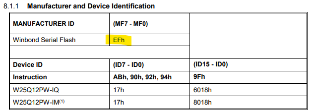
We are using Winbond W25Q01JVSFIQ SPI Flash
For that, we have made some changes in the device tree.
 
We have added MTD support for Winbond, and added UBIFS support in uboot and kernel menuconfig.
 
on probing in u-boot, we are getting this error:
=> sf probe
jedec_spi_nor flash@0: unrecognized JEDEC id bytes: ff, ff, ff
Failed to initialize SPI flash at 0:0 (error 0)
 
Can you suggest what we are missing.
And hardware / software changes required to boot from SPI Flash?
 
Also, can you suggest which image we can use if we are directly flashing to SPI NOR using SPI NOR Flash Programmer ?

  • Hi,

    Please expect responses in sometime.

    Regards,

    Vaibhav

  • => sf probe
    jedec_spi_nor flash@0: unrecognized JEDEC id bytes: ff, ff, ff
    Failed to initialize SPI flash at 0:0 (error 0)
     

    Can you probe the SPI clock/data signals with a logic analyzer and see if there is any activity? Is the clock signal present during `sf probe` and is the frequency as expected? Is the AM62x clocking out commands as expected? Is the QSPI flash responding at all? This will help validate pinmux etc. setup.

    And hardware / software changes required to boot from SPI Flash?

    The TRM has a section in it describing how SPI bootmode is configured/used.

    Also, can you suggest which image we can use if we are directly flashing to SPI NOR using SPI NOR Flash Programmer ?

    In case of using our Linux SW stack you'd just need to flash the different boot images (tiboot3.bin, tispl.bin, u-boot.img) to the appropriate offsets that are expected, there's nothing "special" required here beyond that really. The SDK User's Guide has some info on this, see: https://software-dl.ti.com/processor-sdk-linux/esd/AM62X/11_00_09_04/exports/docs/linux/Foundational_Components/U-Boot/UG-QSPI.html#ospi-qspi-nor-nand (you'll need to scroll down a little bit). Similar instructions exists for using Linux to do the same.

    Regards, Andreas

  • We were able to resolve the prior issues by changing the flash IC. We were trying to boot from the IC which operated on 3.3V but our board was set for 1.8V. We added support for the new IC (Macronix MX25U51245GMI00) in our software. On probing we are now able to detect IC and are getting the following output
    => sf probe
    SF: Detected mx25u51245g with page size 256 Bytes, erase size 4 KiB, total 64 MiB

    We performed the following steps in UBoot console to flash the QSPI NOR flash from the sd card:

    => load mmc 1:1 ${loadaddr} tiboot3.bin
    294113 bytes read in 46 ms (6.1 MiB/s)
    => sf update $loadaddr 0x0 $filesize
    device 0 offset 0x0, size 0x47ce1
    294113 bytes written, 0 bytes skipped in 0.91s, speed 3203954 B/s
    => load mmc 1:1 ${loadaddr} tispl.bin
    1159931 bytes read in 117 ms (9.5 MiB/s)
    => sf update $loadaddr 0x80000 $filesize
    device 0 offset 0x80000, size 0x11b2fb
    1159931 bytes written, 0 bytes skipped in 0.364s, speed 3236428 B/s
    => load mmc 1:1 ${loadaddr} u-boot.img
    1014083 bytes read in 106 ms (9.1 MiB/s)
    => sf update $loadaddr 0x280000 $filesize
    device 0 offset 0x280000, size 0xf7943
    1014083 bytes written, 0 bytes skipped in 0.319s, speed 3224909 B/s

    After this we tried to change to boot from the flash by changing the boot mode to xSPI (bootmode switches as B0 to B15 - 1100111000100100) and QSPI (bootmode switches as B0 to B15 - 1100100000100100) but we are not getting any output on the console.

    Are we missing any steps or are the bootmodes not correct.

  • => sf probe
    SF: Detected mx25u51245g with page size 256 Bytes, erase size 4 KiB, total 64 MiB

    Looks like you have basic operation working once your system is up which is great. Your flash programming steps look good. With this at a minimum `tiboot3.bin` should come up during boot no matter what and do some console prints but looks like you are not even getting that.

    It should not matter since you are using `sf update` but to be sure try adding an `sf erase` step there as well prior to the programming step (and use `sf write` in this case) to see if it makes any difference (with correctly implemented and configured Flash drivers it should not-- but we should double-check that aspect).

    changing the boot mode to xSPI (

    Your Flash seems to support SFDP, so xSPI boot mode in theory should work.

    Have you tried booting from a power-cycle (rather than a reset)? Perhaps the flash is left in a state after flashing in U-Boot that the ROM can't communicate with. This can happen if the Flash reset signal is not connected to the system reset (is yours?). See here for more info: https://e2e.ti.com/support/microcontrollers/arm-based-microcontrollers-group/arm-based-microcontrollers/f/arm-based-microcontrollers-forum/1436064/am2431-spi-and-qspi-boot-modes-using-an-external-flash-w-o-a-dedicated-reset-pin/5506328#5506328     Trying the boot from a power-up could be a good test to see if this issue is at play here.

    Then, can you probe the signals with a logic analyzer if you see any communication on the CLK, data in, and data out signals?

    Are we missing any steps or are the bootmodes not correct.

    Another thing you can try is to use the regular SPI boot mode, and then also cycle through all the different boot mode configuration settings it has to see if any of those work. And also do all that from a cold boot (power-on) to be sure.

    Regards, Andreas

  • We tried different bootmodes but are still unable to get any output on the console.We were getting activity on the data lines and clock during sf read/write commands.

    We followed the following commands with sf erase:

    sf probe
    
    sf erase 0x0 0x680000
    
    load mmc 1:1 ${loadaddr} tiboot3.bin
    
    sf write $loadaddr 0x0 $filesize
    
    load mmc 1:1 ${loadaddr} tispl.bin
    
    sf write $loadaddr 0x80000 $filesize
    
    load mmc 1:1 ${loadaddr} u-boot.img
    
    sf write $loadaddr 0x280000 $filesize

    We changed the bootmodes while the board is on and then gave reset signal to check will the board boot or getting any activity on the spi data lines or clock lines but we are not getting any activity.

  • We changed the bootmodes while the board is on and then gave reset signal to check will the board boot or getting any activity on the spi data lines or clock lines but we are not getting any activity.

    Try power cycling the board as I communicated earlier. The bootmode pins will only get read/latched on a very specific low-level reset, and at least on our EVMs pushing the on-board reset buttons almost never is enough to re-capture the bootmode pin status. Your best bet to be 100% sure is to go though a power cycle.

    The TRM has the details on this if you are curious...

    Regards, Andreas

  • We tried different bootmode with power cycling the board each time along with providing the reset signal on flash (we attached a wire directly from the ICs reset pin to "RESETSTATz" signal) but are still not getting any activity.

    Is there anywhere in the device tree or anywhere else where we can specify the flash's operating voltage (as it is possible for sd card)

  • I'm out on PTO this week but will look at this again next week.

    Regards, Andreas

  • Is there any update on this issue

  • we attached a wire directly from the ICs reset pin to "RESETSTATz" signa

    This signal is the "Main Domain warm reset status output", and is an output from the device POV.

    What you need to assert is the MCU_PORz signal, which is the "MCU Domain cold reset". It is a device input, and the most impactful way to do a device reset, and it also ensures that the bootmode pins are read and latched.

    Regards, Andreas

  • We used the RESETSTATz as in the reference design it along with the OSPI0_CSN1 (used as GPIO_OSPI_RSTn) were used for flash reset. We will try with the MCU_PORz signal to see if it changes anything.

    The TRM mentions: "When using a OSPI\xSPI\QSPI\SPI flash device greater than 128Mb, a flash device package with a RESET
    signal must be used" so if we use a flash IC of 128 Mb would we be able to boot without any reset signal to the flash?

  • so if we use a flash IC of 128 Mb would we be able to boot without any reset signal to the flash?

    Yes. The connection of the reset signal is mostly to be able to better recover from certain operating and failure scenarios through a reset, so the boot ROM firmware has a "clean" (unconfigured) device to talk to. This aspect however should not affect your ability to do the initial boot after power-up, which is what you are having issues with.

    Regards, Andreas

  • As said, we bought a 128 Mb flash (W25Q12PWSFIM) and are trying to boot from this. If we trying to probe the flash without adding the specific drivers we get the following issue:

    sf probe
    jedec_spi_nor flash@0: unrecognized JEDEC id bytes: df, 00, 30
    Failed to initialize SPI flash at 0:0 (error 0)

    After including the JEDEC id and adding the following line in drivers/mtd/spi/spi-nor-ids.c:

    { INFO("w25q12pwsfim", 0xdf0030, 0, 64 * 1024, 256, SECT_4K | SPI_NOR_DUAL_READ | SPI_NOR_QUAD_READ ) }

    and enabling the following in the menu conf:

    -> Device Drivers -> MTD Support -> SPI Flash Support ->Winbond SPI flash support

    we are getting the following error after probing the flash (sf probe):

    Failed to initialize SPI flash at 0:0 (error 0)

  • I'm currently traveling international for business. Please allow a few days for a response.

  • Any update on this case?

  • So this thread now discusses 3 (!)  different Flash parts; I'm a bit confused what is going on here actually.

    1. W25Q01JVSFIQ 
    2. MX25U51245GMI00
    3. W25Q12PWSFIM

    Assuming what you want now is #3, something very basic is off.

    When I search for the datasheet for this W25Q12PW part I find this here: https://www.winbond.com/hq/support/documentation/downloadV2022.jsp?__locale=en&xmlPath=/support/resources/.content/item/DA00-W25Q12PW.html&level=1

    Is this the correct datasheet?

    It is a Winbond part, and it has a manufacturer ID of EFh. However what you are reading is DFh? If that's the case there could be some basic electric/connectivity issue that you would want to analyze further. You may also want tom reduce the SPI clock speed to see if this helps in any way.

    Regards, Andreas

  • Sorry for not making myself clear in the last question, but you got the correct flash. We are trying to boot from the qspi flash on our custom board based on SK-AM62. We first tried using MX25U51245GMI00 but as it was greater than 128 Mb it required a reset to the flash which we did not have on our board. So we switched to W25Q12PWSFIM which is 128 Mb but are getting the issues mention in the last question. We have a flash socket on the board so we simply replaced the flash on the same board which is providing proper ID on probing MX25U51245GMI00 and also successfully writing to the flash. So I doubt it's a connectivity issue, but I'll check again just in case. Could there be any other reason for this problem. (Just to clear the confusion we are getting the issue on W25Q12PWSFIM and are asking for assistance on the same)

  • Thanks for the clarification. I'm on PTO this week. Will be picking up E2E support again next week.

  • Can we get an update on this case

  • So we switched to W25Q12PWSFIM which is 128 Mb but are getting the issues mention in the last question.

    So the JTAG manufacturer ID you should be reading is 0xEF. But you are reading 0xDF, which is not correct. Looks like two bits in the sequence are flipped. I know you mentioned earlier you were able to successfully probe a different Flash chip which means the basic wiring should be ok but perhaps there's something about using that W25Q12 chip that makes it more sensitive to noise/signaling in your setup.

    Since you are using a socket (which should probably never be used for production), you should try to derate the transfer speed/parameters to see if you can get the chip ID to read correctly, even if it is just for testing purposes.

    Try changing these things here (example):

    &ospi0 {
         pinctrl-names = "default";
         pinctrl-0 = <&ospi0_pins_default>;
         status = "okay";
    
         serial_flash: flash@0 {
                 compatible = "jedec,spi-nor";
                 reg = <0x0>;
                 spi-tx-bus-width = <8>;            /* <-- Use <1> here */
                 spi-rx-bus-width = <8>;            /* <-- Use <1> here */
                 spi-max-frequency = <25000000>;    /* <-- Use <1000000> here */
                 cdns,tshsl-ns = <60>;
                 cdns,tsd2d-ns = <60>;
                 cdns,tchsh-ns = <60>;
                 cdns,tslch-ns = <60>;
                 cdns,read-delay = <0>;
         };
    };

    Regards, Andreas

  • We applies the patch suggested by you and were able to make it work, so it seems to be as you suggested.

    After probing the flash we flashed the U-Boot files onto the flash:

     sf probe
    SF: Detected w25q128jw with page size 256 Bytes, erase size 4 KiB, total 16 MiB
    load mmc 1:1 ${loadaddr} tiboot3.bin
    293089 bytes read in 41 ms (6.8 MiB/s)
    sf update $loadaddr 0x0 $filesize
    device 0 offset 0x0, size 0x478e1
    293089 bytes written, 0 bytes skipped in 1.236s, speed 242230 B/s
    load mmc 1:1 ${loadaddr} tispl.bin
    1243171 bytes read in 121 ms (9.8 MiB/s)
    sf update $loadaddr 0x80000 $filesize
    device 0 offset 0x80000, size 0x12f823
    1243171 bytes written, 0 bytes skipped in 5.209s, speed 244245 B/s
    load mmc 1:1 ${loadaddr} u-boot.img
    988099 bytes read in 98 ms (9.6 MiB/s)
    sf update $loadaddr 0x280000 $filesize
    device 0 offset 0x280000, size 0xf13c3
    988099 bytes written, 0 bytes skipped in 4.157s, speed 243165 B/s

    After that we changed the bootmode switch to xSPI mode (1100111000000000) and got the following results:

    U-Boot SPL 2023.04-ti-g2bedcd265ca6 (May 13 2025 - 07:07:38 +0000)
    SYSFW ABI: 4.0 (firmware rev 0x000a '10.1.8--v10.01.08 (Fiery Fox)')
    SPL initial stack usage: 13408 bytes
    Trying to boot from SPI
    jedec_spi_nor flash@0: unrecognized JEDEC id bytes: ef, 80, 18
    SPI probe failed.
    SPL: failed to boot from all boot devices
    ERROR ### Please RESET the board ###

    We assume that this error may be occurring due to an issues in the "tispl.bin" file from the secondary bootloader but we used the same file to boot from SDcard and did not get any error. Or an issue caused because of the mismatch in the frequency of the flash and the one set in the bootmode. Can you spot what the issue may be. In the meanwhile we will also try from our side. 

  • We found the issue to be in the way the boot image checks for the flash JEDEC ID. For some reason when in U-Boot the board loads "tiboot3.bin" only the id for cypress flash were checked giving us the error. We added our flash's JEDEC ID in the "spi-nor-ids.c" file along with the cypress one and were able to resolve it. Why this may be caused and the method we used feels like a work around rather than resolving it, so is there a way to properly do this.

  • We applies the patch suggested by you and were able to make it work, so it seems to be as you suggested.

    Great, thanks for the feedback.

    We added our flash's JEDEC ID in the "spi-nor-ids.c" file along with the cypress one and were able to resolve it.

    If your Flash is a Winbond Flash, the ID should be added to the respective #ifdef CONFIG_SPI_FLASH_WINBOND ... #endif section. And you'd need to make sure that CONFIG_SPI_FLASH_WINBOND is enabled for U-Boot SPL R5. Then it should work. If it doesn't work like this feel free to provide your complete patch that adds the ID and the updated defconfig and I can have a closer look.

    Regards, Andreas

  • CONFIG_SPI_FLASH_WINBOND is enabled for U-Boot SPL R5

    We were able to boot after we made the changes you suggested. We added the Winbond flash ID in the am62x_evm_a53_defconfig

    the ID should be added to the respective #ifdef CONFIG_SPI_FLASH_WINBOND

    The flash ID was already present in "spi-nor-ids.c"

    {
    INFO("w25q128jw", 0xef8018, 0, 64 * 1024, 256,
    SECT_4K | SPI_NOR_DUAL_READ | SPI_NOR_QUAD_READ |
    SPI_NOR_HAS_LOCK | SPI_NOR_HAS_TB)
    },