Part Number: SK-AM64B
Tool/software:
Hi,
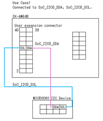
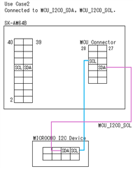
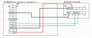
When I call I2C_probe() while supplying 3.3V power through the user expansion connector,
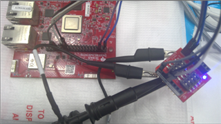
an error occurs, and when I check the waveform with an oscilloscope, it seems to be a NACK.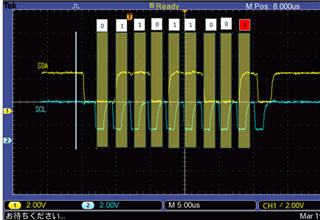
Also, the voltage has already risen from 0V to 0.7V before 3.3V is supplied from the user expansion connector.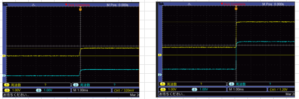
Q1 Is it normal for the voltage to already rise to 0.7V before supplying 3.3V through the user expansion connector?
Q2 Is the error (NAK) in I2C_probe() due to the fact that it is 0.7V before rising to 3.3V?
Regards,
Yukinobu