This thread has been locked.

If you have a related question, please click the "Ask a related question" button in the top right corner. The newly created question will be automatically linked to this question.

AM6442: Sigma Delta Interface Slew Rate

Part Number: AM6442

Tool/software:

I'm working with a customer that is looking for some datasheet clarity around the Sigma Delta signal requirements. From the datasheet:

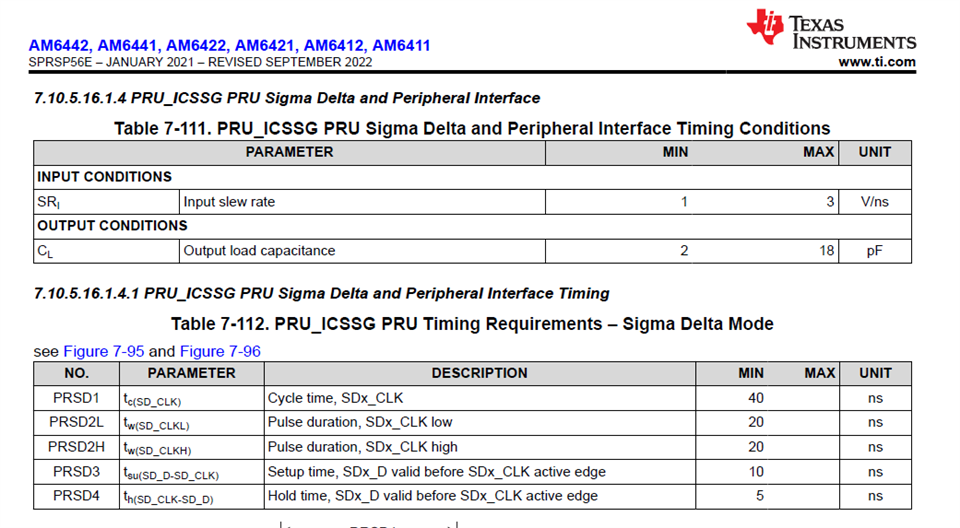
  1. Is this slew rate a requirement on the input signals to the PRU? I’m asking because the table is named “…Timing Conditions” as opposed to the next table which clearly states “…Timing Requirements…”.
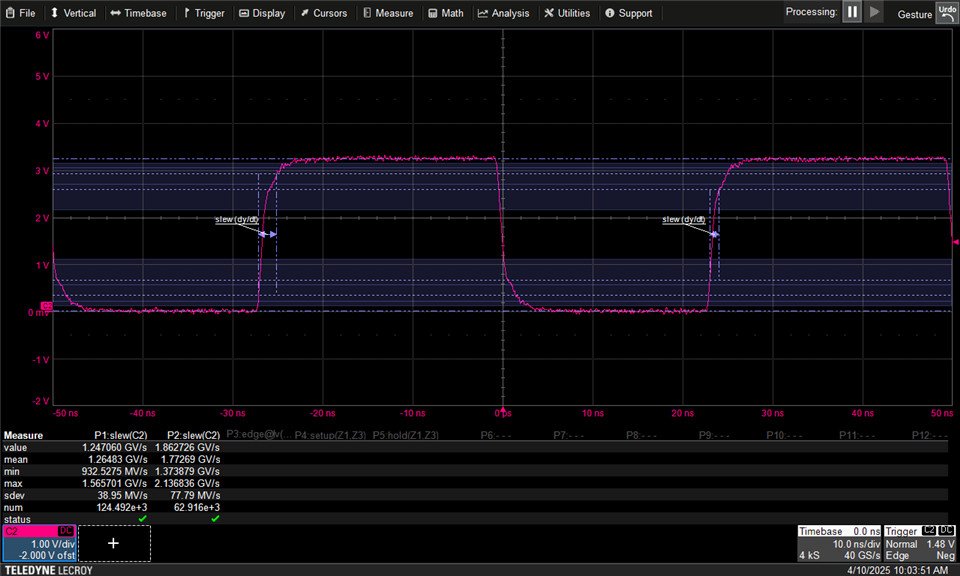
  2. If this is indeed a requirement, are there any measurement specification, like what percentage voltages of the edge the slew rate should be measured? My scope can measure a 10%-90% slew rate and a 20%-80% slew rate. Shown below is both the measurements on two edges. As you can see, there is quite a difference in the measured values:

Thanks,

Stuart

  • The input slew rate range defined in the Timing Conditions table was used during timing closure of the peripheral.

    The parameter values defined in the Timing Requirement and Switching Characteristics tables are based on the conditions defined in the Timing Conditions tables.

    I will need to discuss your question about 20/80 vs 10/90 with our timing closure team. I'm not expecting an issue with the measured slew rates since the mean value of both exceed the min limit and the min measured values is very close to the min limit.

    Regards,
    Paul

  • I confirmed timing was closed with the assumption of 10/90 slew rate.

    Regards,
    Paul

  • Paul,

    Thanks for your updated reply. I have some addition feedback from the customer which I'm hoping you can comment on.

    Is my understanding correct that slew rate is not an electrical requirement on the input buffer? Instead, it is a representation of the conditions under which the timing measurements were made. This is not explicitly mentioned, but is it fair to interpret that the timing measurements were made at the 50% voltage point of the edge? If yes, I think the way I’m measuring setup and hold nullifies the impact slew-rate. I’m measuring the time between clock and data at their ViH or ViL, whichever results in the shortest (worst-case) time. For example, in the waveform shown below, the setup is measured between the ViL of the falling data and ViH of the rising clock.

    Would you agree that as long as I measure times this way, the slew rate is immaterial? The reason I’m asking this is there are some sigma-delta signals that travel across two ribbon cables, and I anticipate those to not meet the slew rate conditions in the datasheet.

    Thanks,

    Stuart

  • Timing closure is based on the method defined in the respective industry standard when there is one. For example, the eMMC standard defines setup as the time from the DAT signal being valid (above VIH or below VIL) before the CLK signal crosses 50% and defines hold as the time the DAT signal remains valid (above VIH or below VIL) after the CLK signal crosses 50%. In this example, the signal slew rate will impact setup and hold times. Other industry standards like RGMII define setup and hold to be measured from the 50% point on each signal.

    I agree your measurement approach would yield the worst-case setup and hold times.

    Regards,
    Paul