This thread has been locked.

If you have a related question, please click the "Ask a related question" button in the top right corner. The newly created question will be automatically linked to this question.

WD_OUT low period control

Hi,

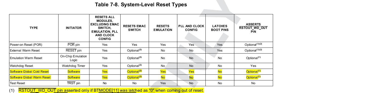
         We verified the WDT overflow reset function and it worked that WD_OUT would pull low while overflow occurred. Unfortunately we found that the low period of WD_OUT was not changed no matter what pre-scaler value I set. I tried to set the register WDT_WCLR[5]=1 (pre-scaler enabled) and WDT_WCLR[4:2]=0 to 7, the WD_OUT pulse width was always about 600ns as the attached waveform figure shown.

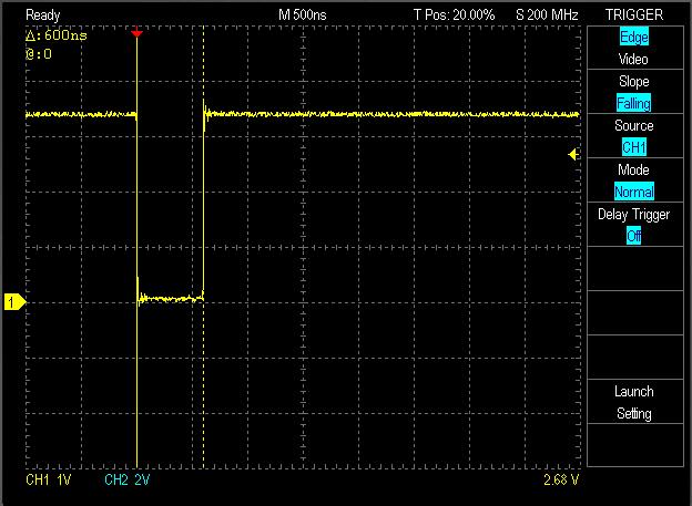
         In TRM 25.2.5, it described that “This pulse is one prescaled timer clock cycle wide and occurs at the same time as the timer counter overflow.” Does it mean the pulse width varies by pre-scaler value? Or it has the fixed width?

         p.s. The overflow rate (OVF_Rate) changed by pre-scaler. 

Regards,

    Eric

  • Eric,


    The clock is SYS_CLK. SYS_CLK is the clock from OSC0 (the primary clock toDM8148 ) and the formula in a more general way is    

                WDOUT pulse width = 300 ns + RSTTIME1 * 1 cycle of SYS_CLK in ns

    Regards,

    Viet

  • Hi Viet,

        In section 25.1.1 and 25.2.1 of TRM, it described that the function clock input is CLKIN32 which is 32KHz. Is"SYS_CLK" the 32KHz CLKIN32 or 20MHz OSC0?

        I measured WD_OUT pulse width = 600ns. The reset default value of RSTTIME1 is 6. It would match my measurement if SYS_CLK is 20MHz:

        WD_OUT pulse width = 300 ns + RSTTIME1 * 1 cycle of SYS_CLK in ns = 300ns + 6 * (10^9ns/20MHz) = 600ns. So is it correct that SYS_CLK is 20MHz?


        The max. value of RSTTIME1 is 255. If above statement is true, the range of WD_OUT pulse width would be [300ns, 13050ns]. 

        In point 7 of table 7-10 in the document "SPRS647B–MARCH 2011–REVISED SEPTEMBER 2011", the minimum delay time from POR high to RSTOUT_WD_OUT high is 0. This delay time includes the WD_OUT pulse (as shown in figure7-4) which should be at least 300ns according to the fomula. It looks some conflict. May you please check it?

        Thank you.


    Regards,

        Eric

  • We modified the PRM_RSTTIME.RSTTIME1 register to change the reset duration and we see the reset duration changing.

    The sys clock used is 20MHz clock and the formula is 300+ (<RSTTIME1 value> * 50) ns

    We checked with the values of 0x1006, 0x100C, 0x1018, 0x101D, 0x1040 and in all the cases the reset duration changed as per the formula mentioned above.

    BR,

    Viet

  • Viet

    is following formla working only at watchdog overflow reset function? how about wdout as software reset? is following formula applicable as software reset? wdout signal can be observed as software reset according to table 7-8.  but we can not notice plus width change even we  PRM_RSTTIME.RSTTIME1  as software reset.

    WDOUT pulse width = 300 ns + RSTTIME1 * 1 cycle of SYS_CLK in ns

    BR

    dong

  • Hi Viet

         We are using dm8168, and also want to control period of  WD_OUT pin. I tried to modify the RSTTIME1 , but the output signal of WD_OUT also is about 750ns.

    Maybe in the DM8168, need to change another register?

    Thanks,

    Best Regards, Guan Qing 

  • Hi Guan,

    In DM814x, we can NOT control RSTOUT_WD_OUT signal duration by RSTTIME1 and RSTTIME2 bit fields from the PRM_RSTTIME register, when the reset is generated from software global cold/warm reset.

    When reset is generated from software global warm reset, PRM_RSTCTRL[0] RST_GLOBAL_WARM_SW = 0x1:
    - RSTTIME2 value has no impact
    - RSTTIME1 value has no impact
    - RSTOUT_WD_OUT is 750ns

    When reset is generated from software global cold reset, PRM_RSTCTRL[1] RST_GLOBAL_COLD_SW = 0x1:
    - RSTTIME2 value has no impact
    - RSTTIME1 value has no impact
    - RSTOUT_WD_OUT is 800ns

    Make sure the reset is generated from the Watchdog timer, not from global reset.

    Regards,
    Pavel
  • Hi Pavel

        We are using DM8168. Is there any different betweent DM816X and DM814X in WD_OUT period controlling ? 

    Thinks

    Best Regards,

    Guan Qing


  • Guan,

    DM814x has single pin RSTOUT_WD_OUTn (active low), while DM816x have two pins WD_OUT (H37) (active high) and RSTOUTn (G37) (active low). I think PRM_RSTTIME will control RSTOUTn (G37) period, not WD_OUT (H37) period. RSTOUTn is asserted at Watchdog reset and other resets also (PORn, RESETn, etc).

    Other difference between DM814x and DM816x regarding WDTimer is that there are two advisories (1.1.37 and 2.1.65) in the DM816x Silicon errata.

    Regards,
    Pavel
  • Hi Pavel

        Thanks for your help. In DM816x,  is there any other method to change the period of WD_OUT?  Now, it is too short (only less 1us) !

    Best Regards,

    Guan  Qing

  • Guan,

    Check DM816x TRM, chapter 22 Watchdog Timer. You can try with modifying the prescaler value WCLR[4:2] PTV. In the initial post, Eric Chen state that this prescaler value does not impact the RSTOUT_WD_OUT pulse duration, but this might not be the case with the DM816x WD_OUT. You can test this.

    Regards,
    Pavel

  • guan said:
     is there any other method to change the period of WD_OUT?  Now, it is too short (only less 1us) !

    Can you clarify if you actually mean you need to control the active pulse of the WD_OUT? To increase (from 1us to bigger value) the high level of the signal?

    Regards,
    Pavel