This thread has been locked.

If you have a related question, please click the "Ask a related question" button in the top right corner. The newly created question will be automatically linked to this question.

TDA4VM: SDK version is TDA4VM_SDK_10.05, How to use the psdkla of dispc.c and dsi.c to configure the DSI and timing parameters

Part Number: TDA4VM
Other Parts Discussed in Thread: TDA4VH, SN65DSI86, DLPC3433, TFP410, SN65DSI83, TPD12S015

Tool/software:

Hi team

I use the sdk is TDA4VM_SDK_10.05,

I want to port the configuration of the ds90ub941 from PSDKRA to PSDKLA.

However, I don't know how to do it. I've examined the PSDKLA code and found two files:

psdkla/board - support/ti - linux - kernel - 6.6.32+git - ti/drivers/gpu/drm/omapdrm/dss/dsi.c

and

psdkla/board - support/ti - linux - kernel - 6.6.32+git - ti/drivers/gpu/drm/omapdrm/dss/dispc.c.

Is it sufficient for me to simply write the probe code for the ds90ub941, initialize its registers, and then use the dispc.c and dsi.c files to configure the DSI and timing parameters?

If so, could you tell me how to use the dispc.c and dsi.c files for DSI and timing parameter configuration?

Regards,

FuGuojia

  • Hi FuGuojia,

    A new bridge driver will need to be developed for ds90ub941.

    An example of a bridge from DSI to a different interface can be found for our TDA4VH EVM boards: https://git.ti.com/cgit/ti-linux-kernel/ti-linux-kernel/tree/arch/arm64/boot/dts/ti/k3-j784s4-evm.dts?h=ti-linux-6.1.y#n1162. They use a sn65dsi86 bridge between DSI to eDP. In terms of connection between drivers, the example connects ti,j721e-dss -> ti,j721e-dsi -> ti,sn65dsi86 -> ti,panel-edp

    For ds90ub941, a driver similar to sn65dsi86 that does the register initialization, and a panel that sets up the timing parameters would be needed.

    Regards,

    Takuma

  • Hi Takuma

    I've taken a look and found that the sn65dsi86 is an Automotive MIPI® DSI bridge to eDP,

    while the ds90ub941 is a DSI to FPD-Link III bridge serializer evaluation module.

    They are two different things.

    Is my train of thought correct in that I can use the dispc.c and dsi.c modules to configure the DSI parameters,

    and I can directly write the ds90ub941 probe to configure the parameters of the ds90ub941?

    An example of a bridge from DSI to a different interface can be found for our TDA4VH EVM boards: https://git.ti.com/cgit/ti-linux-kernel/ti-linux-kernel/tree/arch/arm64/boot/dts/ti/k3-j784s4-evm.dts?h=ti-linux-6.1.y#n1162. They use a sn65dsi86 bridge between DSI to eDP. In terms of connection between drivers, the example connects ti,j721e-dss -> ti,j721e-dsi -> ti,sn65dsi86 -> ti,panel-edp

    If I follow your method, in which file should I configure the DSI timing parameters?

    Regards,

    FuGuojia

  • Hi FuGuojia,

    while the ds90ub941 is a DSI to FPD-Link III bridge serializer evaluation module.

    They are two different things.

    Yes, they are two different things. There are no DSI to FPD-Link bridge driver available in Linux, so I gave the closest thing that I can find, which is a bridge between two different interfaces, where the target interface is not an actual panel, but another connector that takes a fixed display parameter.

    Is my train of thought correct in that I can use the dispc.c and dsi.c modules to configure the DSI parameters,

    and I can directly write the ds90ub941 probe to configure the parameters of the ds90ub941?

    Yes.

    If I follow your method, in which file should I configure the DSI timing parameters?

    panel-simple: https://github.com/torvalds/linux/blob/master/drivers/gpu/drm/panel/panel-simple.c

    Regards,

    Takuma

  • Hi

    Takuma

    Is my train of thought correct in that I can use the dispc.c and dsi.c modules to configure the DSI parameters,

    and I can directly write the ds90ub941 probe to configure the parameters of the ds90ub941?

    Yes.

    If so, could you tell me how to use the dispc.c and dsi.c files for DSI and timing parameter configuration?

    For example, what command can be used to configure this parameter?

    In addition, I have found the serializer of ds90ub953.c in the SDK library. Can I use it as a sample to write the code for ds90ub941.c?

    Regards,

    Takuma

  • Hi FuGuojia,

    In addition, I have found the serializer of ds90ub953.c in the SDK library. Can I use it as a sample to write the code for ds90ub941.c?

    The ds90ub953 is very different since it is a CSI to FPD-Link bridge, so it goes through the capture pipeline instead of display pipeline. 

    If so, could you tell me how to use the dispc.c and dsi.c files for DSI and timing parameter configuration?

    Apologies, it is not dispc.c. This is the old display driver.

    Instead, your display pipeline would look something like: ti,j721e-dss -> ti,j721e-dsi -> your implementation of ds90ub941 -> simple-panel or your implementation of a panel. The simple-panel driver will configure the timing parameters.

    Regards,

    Takuma

  • Hi

    Takuma

    Instead, your display pipeline would look something like: ti,j721e-dss -> ti,j721e-dsi -> your implementation of ds90ub941 -> simple-panel or your implementation of a panel. The simple-panel driver will configure the timing parameters.

    So, the display pipeline you mentioned  and simple-panel  need to be configured in the device tree?

    Regards,

    FuGuojia

  • Hi FuGuojia,

    simple-panel driver will need to be modified, unless there is already a panel with your desired parameters exist. The ds90ub941 driver does not exist, so you must create this driver. After this, the display pipeline is connected using the devicetree.

    Regards,

    Takuma

  • Hi Takuma

    I have already finished writing the driver for the 941 and completed its initialization, as shown in the attachment.

    // SPDX-License-Identifier: GPL-2.0
    /*
     * Copyright (c) 2018, The Linux Foundation. All rights reserved.
     * datasheet: https://www.ti.com/lit/ds/symlink/ds90ub941.pdf
     */
    
     #include <linux/atomic.h>
     #include <linux/auxiliary_bus.h>
     #include <linux/bitfield.h>
     #include <linux/bits.h>
     #include <linux/clk.h>
     #include <linux/debugfs.h>
     #include <linux/gpio/consumer.h>
     #include <linux/gpio/driver.h>
     #include <linux/i2c.h>
     #include <linux/iopoll.h>
     #include <linux/module.h>
     #include <linux/of_graph.h>
     #include <linux/pm_runtime.h>
     #include <linux/pwm.h>
     #include <linux/regmap.h>
     #include <linux/regulator/consumer.h>
     
     #include <asm/unaligned.h>
     
     #include <drm/display/drm_dp_aux_bus.h>
     #include <drm/display/drm_dp_helper.h>
     #include <drm/drm_atomic.h>
     #include <drm/drm_atomic_helper.h>
     #include <drm/drm_bridge.h>
     #include <drm/drm_bridge_connector.h>
     #include <drm/drm_edid.h>
     #include <drm/drm_mipi_dsi.h>
     #include <drm/drm_of.h>
     #include <drm/drm_panel.h>
     #include <drm/drm_print.h>
     #include <drm/drm_probe_helper.h>
     
     #define SN_DEVICE_REV_REG			0x08
     #define SN_DPPLL_SRC_REG			0x0A
     #define  DPPLL_CLK_SRC_DSICLK			BIT(0)
     #define  REFCLK_FREQ_MASK			GENMASK(3, 1)
     #define  REFCLK_FREQ(x)				((x) << 1)
     #define  DPPLL_SRC_DP_PLL_LOCK			BIT(7)
     #define SN_PLL_ENABLE_REG			0x0D
     #define SN_DSI_LANES_REG			0x10
     #define  CHA_DSI_LANES_MASK			GENMASK(4, 3)
     #define  CHA_DSI_LANES(x)			((x) << 3)
     #define SN_DSIA_CLK_FREQ_REG			0x12
     #define SN_CHA_ACTIVE_LINE_LENGTH_LOW_REG	0x20
     #define SN_CHA_VERTICAL_DISPLAY_SIZE_LOW_REG	0x24
     #define SN_CHA_HSYNC_PULSE_WIDTH_LOW_REG	0x2C
     #define SN_CHA_HSYNC_PULSE_WIDTH_HIGH_REG	0x2D
     #define  CHA_HSYNC_POLARITY			BIT(7)
     #define SN_CHA_VSYNC_PULSE_WIDTH_LOW_REG	0x30
     #define SN_CHA_VSYNC_PULSE_WIDTH_HIGH_REG	0x31
     #define  CHA_VSYNC_POLARITY			BIT(7)
     #define SN_CHA_HORIZONTAL_BACK_PORCH_REG	0x34
     #define SN_CHA_VERTICAL_BACK_PORCH_REG		0x36
     #define SN_CHA_HORIZONTAL_FRONT_PORCH_REG	0x38
     #define SN_CHA_VERTICAL_FRONT_PORCH_REG		0x3A
     #define SN_LN_ASSIGN_REG			0x59
     #define  LN_ASSIGN_WIDTH			2
     #define SN_ENH_FRAME_REG			0x5A
     #define  VSTREAM_ENABLE				BIT(3)
     #define  LN_POLRS_OFFSET			4
     #define  LN_POLRS_MASK				0xf0
     #define SN_DATA_FORMAT_REG			0x5B
     #define  BPP_18_RGB				BIT(0)
     #define SN_HPD_DISABLE_REG			0x5C
     #define  HPD_DISABLE				BIT(0)
     #define  HPD_DEBOUNCED_STATE			BIT(4)
     #define SN_GPIO_IO_REG				0x5E
     #define  SN_GPIO_INPUT_SHIFT			4
     #define  SN_GPIO_OUTPUT_SHIFT			0
     #define SN_GPIO_CTRL_REG			0x5F
     #define  SN_GPIO_MUX_INPUT			0
     #define  SN_GPIO_MUX_OUTPUT			1
     #define  SN_GPIO_MUX_SPECIAL			2
     #define  SN_GPIO_MUX_MASK			0x3
     #define SN_AUX_WDATA_REG(x)			(0x64 + (x))
     #define SN_AUX_ADDR_19_16_REG			0x74
     #define SN_AUX_ADDR_15_8_REG			0x75
     #define SN_AUX_ADDR_7_0_REG			0x76
     #define SN_AUX_ADDR_MASK			GENMASK(19, 0)
     #define SN_AUX_LENGTH_REG			0x77
     #define SN_AUX_CMD_REG				0x78
     #define  AUX_CMD_SEND				BIT(0)
     #define  AUX_CMD_REQ(x)				((x) << 4)
     #define SN_AUX_RDATA_REG(x)			(0x79 + (x))
     #define SN_SSC_CONFIG_REG			0x93
     #define  DP_NUM_LANES_MASK			GENMASK(5, 4)
     #define  DP_NUM_LANES(x)			((x) << 4)
     #define SN_DATARATE_CONFIG_REG			0x94
     #define  DP_DATARATE_MASK			GENMASK(7, 5)
     #define  DP_DATARATE(x)				((x) << 5)
     #define SN_TRAINING_SETTING_REG			0x95
     #define  SCRAMBLE_DISABLE			BIT(4)
     #define SN_ML_TX_MODE_REG			0x96
     #define  ML_TX_MAIN_LINK_OFF			0
     #define  ML_TX_NORMAL_MODE			BIT(0)
     #define SN_PWM_PRE_DIV_REG			0xA0
     #define SN_BACKLIGHT_SCALE_REG			0xA1
     #define  BACKLIGHT_SCALE_MAX			0xFFFF
     #define SN_BACKLIGHT_REG			0xA3
     #define SN_PWM_EN_INV_REG			0xA5
     #define  SN_PWM_INV_MASK			BIT(0)
     #define  SN_PWM_EN_MASK				BIT(1)
     #define SN_AUX_CMD_STATUS_REG			0xF4
     #define  AUX_IRQ_STATUS_AUX_RPLY_TOUT		BIT(3)
     #define  AUX_IRQ_STATUS_AUX_SHORT		BIT(5)
     #define  AUX_IRQ_STATUS_NAT_I2C_FAIL		BIT(6)
     
     #define MIN_DSI_CLK_FREQ_MHZ	40
     
     /* fudge factor required to account for 8b/10b encoding */
     #define DP_CLK_FUDGE_NUM	10
     #define DP_CLK_FUDGE_DEN	8
     
     /* Matches DP_AUX_MAX_PAYLOAD_BYTES (for now) */
     #define SN_AUX_MAX_PAYLOAD_BYTES	16
     
     #define SN_REGULATOR_SUPPLY_NUM		4
     
     #define SN_MAX_DP_LANES			4
     #define SN_NUM_GPIOS			4
     #define SN_GPIO_PHYSICAL_OFFSET		1
     
     #define SN_LINK_TRAINING_TRIES		10
     
     #define SN_PWM_GPIO_IDX			3 /* 4th GPIO */
     
     /**
      * struct ti_ds90ub941 - Platform data for ti-ds90ub941 driver.
      * @bridge_aux:   AUX-bus sub device for MIPI-to-eDP bridge functionality.
      * @gpio_aux:     AUX-bus sub device for GPIO controller functionality.
      * @aux_aux:      AUX-bus sub device for eDP AUX channel functionality.
      * @pwm_aux:      AUX-bus sub device for PWM controller functionality.
      *
      * @dev:          Pointer to the top level (i2c) device.
      * @regmap:       Regmap for accessing i2c.
      * @aux:          Our aux channel.
      * @bridge:       Our bridge.
      * @connector:    Our connector.
      * @host_node:    Remote DSI node.
      * @dsi:          Our MIPI DSI source.
      * @refclk:       Our reference clock.
      * @next_bridge:  The bridge on the eDP side.
      * @enable_gpio:  The GPIO we toggle to enable the bridge.
      * @supplies:     Data for bulk enabling/disabling our regulators.
      * @dp_lanes:     Count of dp_lanes we're using.
      * @ln_assign:    Value to program to the LN_ASSIGN register.
      * @ln_polrs:     Value for the 4-bit LN_POLRS field of SN_ENH_FRAME_REG.
      * @comms_enabled: If true then communication over the aux channel is enabled.
      * @plugged:       Plug connection status
      * @comms_mutex:   Protects modification of comms_enabled.
      *
      * @gchip:        If we expose our GPIOs, this is used.
      * @gchip_output: A cache of whether we've set GPIOs to output.  This
      *                serves double-duty of keeping track of the direction and
      *                also keeping track of whether we've incremented the
      *                pm_runtime reference count for this pin, which we do
      *                whenever a pin is configured as an output.  This is a
      *                bitmap so we can do atomic ops on it without an extra
      *                lock so concurrent users of our 4 GPIOs don't stomp on
      *                each other's read-modify-write.
      *
      * @pchip:        pwm_chip if the PWM is exposed.
      * @pwm_enabled:  Used to track if the PWM signal is currently enabled.
      * @pwm_pin_busy: Track if GPIO4 is currently requested for GPIO or PWM.
      * @pwm_refclk_freq: Cache for the reference clock input to the PWM.
      */
     struct ti_ds90ub941 {
         struct auxiliary_device		*bridge_aux;
         struct auxiliary_device		*gpio_aux;
         struct auxiliary_device		*aux_aux;
         struct auxiliary_device		*pwm_aux;
         struct i2c_client	*client;
     
         struct device			*dev;
         struct regmap			*regmap;
         struct drm_dp_aux		aux;
         struct drm_bridge		bridge;
         struct drm_connector		*connector;
         struct device_node		*host_node;
         struct mipi_dsi_device		*dsi;
         struct clk			*refclk;
         struct drm_bridge		*next_bridge;
         struct gpio_desc		*enable_gpio;
         struct regulator_bulk_data	supplies[SN_REGULATOR_SUPPLY_NUM];
         int				dp_lanes;
         u8				ln_assign;
         u8				ln_polrs;
         bool				comms_enabled;
         bool				plugged;
         struct mutex			comms_mutex;
     
     #if defined(CONFIG_OF_GPIO)
         struct gpio_chip		gchip;
         DECLARE_BITMAP(gchip_output, SN_NUM_GPIOS);
     #endif
     #if defined(CONFIG_PWM)
         struct pwm_chip			pchip;
         bool				pwm_enabled;
         atomic_t			pwm_pin_busy;
     #endif
         unsigned int			pwm_refclk_freq;
     };
     
     u8 Ub941Config[][2] = {
        {0x01, 0x0A}, // Reset
        {0x03, 0x9A}, //Passthrough I2C
        {0x5B, 0x01}, //Force single lane
        {0x1E, 0x01}, //Select FPD-Link III Port 0
        {0x66, 0x1A},
        {0x67, 0x01}, //M=1
        {0x66, 0x03},
        {0x67, 0x03}, //N=2
        {0x66, 0x04},
        {0x67, 0x70}, //least 8 bit of Total Horizontal frame size
        {0x66, 0x05},
        {0x67, 0xE6}, //Least 4 bit TV + Most 4 bit TH
        {0x66, 0x06},
        {0x67, 0x2E}, //Most 8 bit of Total Vertical frame size
        {0x66, 0x07},
        {0x67, 0x00}, //least 8 bit of active Horizontal frame size
        {0x66, 0x08},
        {0x67, 0x05}, //Least 4 bit AV + Most 4 bit AH
        {0x66, 0x09},
        {0x67, 0x2D}, //Most 8 bit of active Vertical frame size
        {0x66, 0x0A},
        {0x67, 0x50}, //Horizontal Sync Width
        {0x66, 0x0B},
        {0x67, 0x05}, //Vertical Sync Width
        {0x66, 0x0C},
        {0x67, 0xD8}, //Horizontal back porch
        {0x66, 0x0D},
        {0x67, 0x16}, //Vertical back porch
        {0x65, 0x04}, //using internal timing and internal clock
        {0x64, 0x15}, //enable PG/color bars
        {0x1E, 0x01}, //Select FPD-Link III Port 0
        {0x07, 0x58}, //0x07,0x58
        {0x08, 0x5C}, //0x08,0x5c
        {0x03, 0x9A}, //0x03,0x9A Enable I2C_PASSTHROUGH, FPD-Link III Port 0
        {0x01, 0x00}, //Release DSI
    
     };
    
    //  static const struct regmap_range ti_ds90ub941_volatile_ranges[] = {
    //      { .range_min = 0, .range_max = 0xFF },
    //  };
     
    //  static const struct regmap_access_table ti_sn_bridge_volatile_table = {
    //      .yes_ranges = ti_ds90ub941_volatile_ranges,
    //      .n_yes_ranges = ARRAY_SIZE(ti_ds90ub941_volatile_ranges),
    //  };
     
     static const struct regmap_config ti_ds90ub941_regmap_config = {
         .reg_bits = 8,
         .val_bits = 8,
         .name = "ds90ub941",
        //  .volatile_table = &ti_sn_bridge_volatile_table,
        //  .cache_type = REGCACHE_NONE,
        //  .max_register = 0xFF,
     };
     
     static int ti_ds90ub941_read(struct ti_ds90ub941 *pdata, u8 reg, u8 *val)
     {
         int ret;
     
        //  ret = regmap_read(pdata->regmap, reg, &v);
        ret = i2c_smbus_read_i2c_block_data(pdata->client, reg, 1, val);
        if (ret)
        {
           printk("DSS DSI ti_ds90ub941  Cannot read register 0x%02x: %d\n", reg, ret);
        } 
        else 
        {
           printk("DSS DSI ti_ds90ub941  read register 0x%02x: %d\n", reg, *val);
        }
     
         return ret;
     }
     
     static int ti_ds90ub941_write(struct ti_ds90ub941 *pdata, u8 reg, u8 val)
     {
         int ret;
        //  ret = regmap_write(pdata->regmap, reg, val);
        ret = i2c_smbus_write_byte_data(pdata->client, reg, val);
         if (ret)
         {
            printk("DSS DSI ti_ds90ub941  Cannot write register 0x%02x: %d\n", reg, ret);
         } 
         else 
         {
            printk("DSS DSI ti_ds90ub941  write register 0x%02x: %d\n", reg, val);
         }
             
         return ret;
     }
     
     static void ti_ds90ub941_cfg_init(struct ti_ds90ub941 *pdata)
     {
         int ret,cnt;
    
        for (cnt = 0; cnt < sizeof(Ub941Config)/2; cnt ++)
        {
            ret = ti_ds90ub941_write(pdata, Ub941Config[cnt][0], Ub941Config[cnt][1]);
            if (ret) {
                printk("DSS DSI ti_ds90ub941  Cannot write register 0x%02x: %d\n", Ub941Config[cnt][0], ret);
                break;
            }
         }
     
         usleep_range(10000, 10500); /* 10ms delay recommended by spec */
     }
     
     
     static int ti_ds90ub941_probe(struct i2c_client *client)
     {
         struct device *dev = &client->dev;
         struct ti_ds90ub941 *pdata;
     
    
         printk("DSS DSI ti_ds90ub941 START\n");
         if (!i2c_check_functionality(client->adapter, I2C_FUNC_I2C)) {
             printk("DSS DSI ti_ds90ub941 device doesn't support I2C\n");
             return -ENODEV;
         }
         printk("DSS DSI ti_ds90ub941 START1\n");
         pdata = devm_kzalloc(dev, sizeof(struct ti_ds90ub941), GFP_KERNEL);
         if (!pdata)
             return -ENOMEM;
         dev_set_drvdata(dev, pdata);
         pdata->dev = dev;
         pdata->client = client;
     
         mutex_init(&pdata->comms_mutex);
    
         pdata->enable_gpio = devm_gpiod_get_optional(dev, "enable",
    						     GPIOD_OUT_HIGH);
     
         pdata->regmap = devm_regmap_init_i2c(client,
                              &ti_ds90ub941_regmap_config);
         
     
         ti_ds90ub941_cfg_init(pdata);
     
         /*
          * Break ourselves up into a collection of aux devices. The only real
          * motiviation here is to solve the chicken-and-egg problem of probe
          * ordering. The bridge wants the panel to be there when it probes.
          * The panel wants its HPD GPIO (provided by ds90ub941 on some boards)
          * when it probes. The panel and maybe backlight might want the DDC
          * bus or the pwm_chip. Having sub-devices allows the some sub devices
          * to finish probing even if others return -EPROBE_DEFER and gets us
          * around the problems.
          */
    
         printk("DSS DSI ti_ds90ub941 END\n");
         return 0;
     }
     
     static struct i2c_device_id ti_ds90ub941_id[] = {
         { "ti,ds90ub941", 0},
         {},
     };
     MODULE_DEVICE_TABLE(i2c, ti_ds90ub941_id);
     
     static const struct of_device_id ti_ds90ub941_match_table[] = {
         {.compatible = "ti,ds90ub941"},
         {},
     };
     MODULE_DEVICE_TABLE(of, ti_ds90ub941_match_table);
     
     static struct i2c_driver ti_ds90ub941_driver = {
         .driver = {
             .name = "ds90ub941",
             .of_match_table = ti_ds90ub941_match_table,
         },
         .probe = ti_ds90ub941_probe,
         .id_table = ti_ds90ub941_id,
     };
     
     static int __init ti_ds90ub941_init(void)
     {
         int ret;
     
         ret = i2c_add_driver(&ti_ds90ub941_driver);
         if (ret)
             return ret;
     
         return ret;
     }
     module_init(ti_ds90ub941_init);
     
     static void __exit ti_ds90ub941_exit(void)
     {
         i2c_del_driver(&ti_ds90ub941_driver);
     }
     module_exit(ti_ds90ub941_exit);
     
     MODULE_AUTHOR("Sandeep Panda <spanda@codeaurora.org>");
     MODULE_DESCRIPTION("ds90ub941 DSI to eDP bridge driver");
     MODULE_LICENSE("GPL v2");
     

    The device tree configuration is as follows.

    &main_i2c1 {
        status = "okay";
        pinctrl-names = "default";
        pinctrl-0 = <&main_i2c1_pins_default>;
        clock-frequency = <400000>;

        a2b24xx: a2b24xx@0x68 {
            compatible = "adi,a2b24xx";
            reg = <0x68>;
        };
        dsi941bridge: dsi941bridge@0x16 {
            compatible = "ti,ds90ub941";
            reg = <0x16>;

            enable-gpios = <&main_gpio0 78 GPIO_ACTIVE_HIGH>;

            ports {
                    port@0 {
                        reg = <0>;
                        dp1_in: endpoint {
                            remote-endpoint = <&dsi0_out>;
                        };
                    };
                };
            };
        };

    &dsi0_ports {
        port@0 {
            reg = <0>;
            dsi0_out: endpoint {
                remote-endpoint = <&dp1_in>;
            };
        };
    };

    However, when I measured the REFCLK1 pin of the DS90UB941, there was no signal.

    1)I wonder if there is something wrong with my device tree configuration, or if the DSI timing parameters I set haven't been configured successfully?

    When I was compiling panel-simple.c, I had already set CONFIG_DRM_PANEL_SIMPLE=y. However, when I executed zcat /proc/config.gz | grep CONFIG_DRM_PANEL_SIMPLE in the root environment, the result showed CONFIG_DRM_PANEL_SIMPLE=m. I saw in the Kconfig file that it depends on the following three modules.

    2)How can I enable these three modules?

    Regards,

    FuGuojia

  • Hi FuGuojia,

    1)I wonder if there is something wrong with my device tree configuration, or if the DSI timing parameters I set haven't been configured successfully?

    Can you share the full logs from "dmesg" to see if the driver was probed?

    2)How can I enable these three modules?

    Try menuconfig: https://software-dl.ti.com/jacinto7/esd/processor-sdk-linux-jacinto7/10_01_00_04/exports/docs/linux/Foundational_Components_Kernel_Users_Guide.html#configuring-the-kernel

    Regards,

    Takuma

  • Hi Takuma

    1)I wonder if there is something wrong with my device tree configuration, or if the DSI timing parameters I set haven't been configured successfully?

    Can you share the full logs from "dmesg" to see if the driver was probed?

    The log is as shown in the attachment.

    1351.log.txt

    I have already read this article, but I still don't have much of an idea. Could you provide more details?

    Regards,

    FuGuojia

  • Hi FuGuojia,

    Thank you for the logs.

    It seems the DSI driver you have created is being probed. But, none of the display pipeline is being probed...

    In any case, it sounds like you are new to Linux based off of the driver implementation of ds90ub941 and the question about menuconfig. So, I have two options that I can recommend:

    1. Learn how to develop a Linux kernel driver following this training: https://bootlin.com/doc/training/sessions/ti-US.linux-kernel.jun2024/linux-kernel-beagleplay-slides.pdf. This covers everything from creating a device driver to configuring the kernel using menuconfig. 
    2. Or alternatively, hire a third party to do the Linux kernel driver implementation. Some recommended third parties we know of are: Baylibre, Bootlin (who created the above training), and RedHat

    Regards,

    Takuma

  • Hi Takuma

    It seems the DSI driver you have created is being probed. But, none of the display pipeline is being probed...

    What function can I implement by using menuconfig here? Do I just need to enable the CONFIG_DRM_PANEL_SIMPLE option?

    If so,I can't find it.

    Regards,

    FuGuojia

  • Hi FuGuojia,

    Those are the x86 architecture kernel configuration. This can happen if you are not cross compiling and compiling for your PC. You will need the arm64 kernel configuration. You will need to cross compile for arm64. 

    The SDK user guide has the instructions for cross compiling for arm64: https://software-dl.ti.com/jacinto7/esd/processor-sdk-linux-jacinto7/10_01_00_04/exports/docs/linux/Foundational_Components_Kernel_Users_Guide.html

    Regards,

    Takuma

  • Hi Takuma

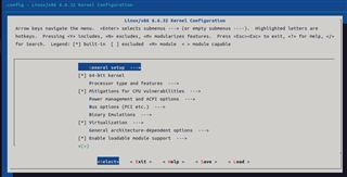
    I have opened the cross compile for arm64, and find the CONFIG_DRM_PANEL_SIMPLE configuration

    It depend the DRM configuration

    but DRM in turn depends on AGP

    However, I can't find the configuration for AGP under Graphics support.

    Could you please tell me where the AGP configuration is located?

    Regards,

    FuGuojia

  • Hi FuGuojia,

    However, I can't find the configuration for AGP under Graphics support.

    Your screenshot looks to show AGP configuration is located... but I do not think AGP is required for DRM. Kernel config says (AGP [=n] || AGP [=n] =n).

    In any case, I will like to point out that your device driver is not complete. It is missing essential Linux code like drm_bridge_add() to register the bridge, and functionality to connect between DSI port and panel port. It is possible to use the driver in a non-standard way, since you seem to have the device specific I2C writes to configure the bridge, but I do not think you are intentionally going down this non-standard path as it requires good knowledge of both Linux and how the device works.

    Again, I recommend going through the free training that I have linked previously, or paying a Linux expert to create the driver, or pay to get consulting/training.

    Regards,

    Takuma

  • Hi Takuma

    I just want to know how to enable the DRM feature. As mentioned before, the AGP that DRM depends on cannot be detected. Can you help me solve this problem first?

    Regards,

    FuGuojia

  • Hi FuGuojia,

    You do not need AGP for DRM. DRM does not depend on AGP. There are no AGP ports on the SoC, so even if enabled it will have no effect.

    If you are using the default configuration, DRM is already enabled. You can confirm by booting up an image and run "zcat /proc/config.gz" to print out all of the kernel configurations that are enabled in the Linux kernel image that is flashed. You can additionally pipe this to a text document which you can inspect on your PC using a text editor (zcat /proc/config.gz > my_config_dump.txt) or use grep to filter for a specific string (zcat /proc/config.gz | grep -i drm).

    Regards,

    Takuma

  • Hi Takuma

    I use the command zcat /proc/config.gz | grep -i drm, and the execution result is as follows.

    CONFIG_DRM=m,It is not work.

    root@j721e-evm:~# zcat /proc/config.gz | grep -i drm
    CONFIG_DRM=m
    CONFIG_DRM_MIPI_DSI=y
    CONFIG_DRM_KMS_HELPER=m
    # CONFIG_DRM_DEBUG_DP_MST_TOPOLOGY_REFS is not set
    # CONFIG_DRM_DEBUG_MODESET_LOCK is not set
    CONFIG_DRM_FBDEV_EMULATION=y
    CONFIG_DRM_FBDEV_OVERALLOC=100
    # CONFIG_DRM_FBDEV_LEAK_PHYS_SMEM is not set
    # CONFIG_DRM_LOAD_EDID_FIRMWARE is not set
    CONFIG_DRM_DP_AUX_BUS=m
    CONFIG_DRM_DISPLAY_HELPER=m
    CONFIG_DRM_DISPLAY_DP_HELPER=y
    CONFIG_DRM_DISPLAY_HDCP_HELPER=y
    # CONFIG_DRM_DP_AUX_CHARDEV is not set
    # CONFIG_DRM_DP_CEC is not set
    CONFIG_DRM_GEM_DMA_HELPER=m
    CONFIG_DRM_I2C_CH7006=m
    CONFIG_DRM_I2C_SIL164=m
    CONFIG_DRM_I2C_NXP_TDA998X=m
    # CONFIG_DRM_I2C_NXP_TDA9950 is not set
    # CONFIG_DRM_HDLCD is not set
    # CONFIG_DRM_MALI_DISPLAY is not set
    # CONFIG_DRM_KOMEDA is not set
    # CONFIG_DRM_RADEON is not set
    # CONFIG_DRM_AMDGPU is not set
    # CONFIG_DRM_NOUVEAU is not set
    # CONFIG_DRM_VGEM is not set
    # CONFIG_DRM_VKMS is not set
    # CONFIG_DRM_VMWGFX is not set
    # CONFIG_DRM_UDL is not set
    # CONFIG_DRM_AST is not set
    # CONFIG_DRM_MGAG200 is not set
    # CONFIG_DRM_QXL is not set
    # CONFIG_DRM_VIRTIO_GPU is not set
    CONFIG_DRM_PANEL=y
    # CONFIG_DRM_PANEL_ABT_Y030XX067A is not set
    # CONFIG_DRM_PANEL_ARM_VERSATILE is not set
    # CONFIG_DRM_PANEL_ASUS_Z00T_TM5P5_NT35596 is not set
    # CONFIG_DRM_PANEL_AUO_A030JTN01 is not set
    # CONFIG_DRM_PANEL_BOE_BF060Y8M_AJ0 is not set
    # CONFIG_DRM_PANEL_BOE_HIMAX8279D is not set
    CONFIG_DRM_PANEL_BOE_TV101WUM_NL6=m
    # CONFIG_DRM_PANEL_DSI_CM is not set
    CONFIG_DRM_PANEL_LVDS=m
    CONFIG_DRM_PANEL_SIMPLE=m
    CONFIG_DRM_PANEL_EDP=m
    # CONFIG_DRM_PANEL_EBBG_FT8719 is not set
    # CONFIG_DRM_PANEL_ELIDA_KD35T133 is not set
    # CONFIG_DRM_PANEL_FEIXIN_K101_IM2BA02 is not set
    # CONFIG_DRM_PANEL_FEIYANG_FY07024DI26A30D is not set
    # CONFIG_DRM_PANEL_HIMAX_HX8394 is not set
    # CONFIG_DRM_PANEL_ILITEK_IL9322 is not set
    # CONFIG_DRM_PANEL_ILITEK_ILI9341 is not set
    CONFIG_DRM_PANEL_ILITEK_ILI9881C=m
    # CONFIG_DRM_PANEL_INNOLUX_EJ030NA is not set
    # CONFIG_DRM_PANEL_INNOLUX_P079ZCA is not set
    # CONFIG_DRM_PANEL_JADARD_JD9365DA_H3 is not set
    # CONFIG_DRM_PANEL_JDI_LT070ME05000 is not set
    # CONFIG_DRM_PANEL_JDI_R63452 is not set
    # CONFIG_DRM_PANEL_KHADAS_TS050 is not set
    # CONFIG_DRM_PANEL_KINGDISPLAY_KD097D04 is not set
    # CONFIG_DRM_PANEL_LEADTEK_LTK050H3146W is not set
    # CONFIG_DRM_PANEL_LEADTEK_LTK500HD1829 is not set
    # CONFIG_DRM_PANEL_SAMSUNG_LD9040 is not set
    # CONFIG_DRM_PANEL_LG_LB035Q02 is not set
    # CONFIG_DRM_PANEL_LG_LG4573 is not set
    # CONFIG_DRM_PANEL_MAGNACHIP_D53E6EA8966 is not set
    # CONFIG_DRM_PANEL_NEC_NL8048HL11 is not set
    # CONFIG_DRM_PANEL_NEWVISION_NV3051D is not set
    # CONFIG_DRM_PANEL_NEWVISION_NV3052C is not set
    # CONFIG_DRM_PANEL_NOVATEK_NT35510 is not set
    # CONFIG_DRM_PANEL_NOVATEK_NT35560 is not set
    # CONFIG_DRM_PANEL_NOVATEK_NT35950 is not set
    # CONFIG_DRM_PANEL_NOVATEK_NT36523 is not set
    # CONFIG_DRM_PANEL_NOVATEK_NT36672A is not set
    # CONFIG_DRM_PANEL_NOVATEK_NT39016 is not set
    CONFIG_DRM_PANEL_MANTIX_MLAF057WE51=m
    # CONFIG_DRM_PANEL_OLIMEX_LCD_OLINUXINO is not set
    # CONFIG_DRM_PANEL_ORISETECH_OTA5601A is not set
    # CONFIG_DRM_PANEL_ORISETECH_OTM8009A is not set
    # CONFIG_DRM_PANEL_OSD_OSD101T2587_53TS is not set
    # CONFIG_DRM_PANEL_PANASONIC_VVX10F034N00 is not set
    # CONFIG_DRM_PANEL_RASPBERRYPI_TOUCHSCREEN is not set
    CONFIG_DRM_PANEL_RAYDIUM_RM67191=m
    # CONFIG_DRM_PANEL_RAYDIUM_RM68200 is not set
    # CONFIG_DRM_PANEL_RONBO_RB070D30 is not set
    # CONFIG_DRM_PANEL_SAMSUNG_ATNA33XC20 is not set
    # CONFIG_DRM_PANEL_SAMSUNG_DB7430 is not set
    # CONFIG_DRM_PANEL_SAMSUNG_S6D16D0 is not set
    # CONFIG_DRM_PANEL_SAMSUNG_S6D27A1 is not set
    # CONFIG_DRM_PANEL_SAMSUNG_S6D7AA0 is not set
    # CONFIG_DRM_PANEL_SAMSUNG_S6E3HA2 is not set
    # CONFIG_DRM_PANEL_SAMSUNG_S6E63J0X03 is not set
    # CONFIG_DRM_PANEL_SAMSUNG_S6E63M0 is not set
    # CONFIG_DRM_PANEL_SAMSUNG_S6E88A0_AMS452EF01 is not set
    # CONFIG_DRM_PANEL_SAMSUNG_S6E8AA0 is not set
    # CONFIG_DRM_PANEL_SAMSUNG_SOFEF00 is not set
    # CONFIG_DRM_PANEL_SEIKO_43WVF1G is not set
    # CONFIG_DRM_PANEL_SHARP_LQ101R1SX01 is not set
    # CONFIG_DRM_PANEL_SHARP_LS037V7DW01 is not set
    # CONFIG_DRM_PANEL_SHARP_LS043T1LE01 is not set
    # CONFIG_DRM_PANEL_SHARP_LS060T1SX01 is not set
    # CONFIG_DRM_PANEL_SITRONIX_ST7701 is not set
    CONFIG_DRM_PANEL_SITRONIX_ST7703=m
    # CONFIG_DRM_PANEL_SITRONIX_ST7789V is not set
    # CONFIG_DRM_PANEL_SONY_ACX565AKM is not set
    # CONFIG_DRM_PANEL_SONY_TD4353_JDI is not set
    # CONFIG_DRM_PANEL_SONY_TULIP_TRULY_NT35521 is not set
    # CONFIG_DRM_PANEL_STARTEK_KD070FHFID015 is not set
    # CONFIG_DRM_PANEL_TDO_TL070WSH30 is not set
    # CONFIG_DRM_PANEL_TPO_TD028TTEC1 is not set
    # CONFIG_DRM_PANEL_TPO_TD043MTEA1 is not set
    # CONFIG_DRM_PANEL_TPO_TPG110 is not set
    CONFIG_DRM_PANEL_TRULY_NT35597_WQXGA=m
    # CONFIG_DRM_PANEL_VISIONOX_RM69299 is not set
    CONFIG_DRM_PANEL_VISIONOX_VTDR6130=m
    # CONFIG_DRM_PANEL_VISIONOX_R66451 is not set
    # CONFIG_DRM_PANEL_WIDECHIPS_WS2401 is not set
    # CONFIG_DRM_PANEL_XINPENG_XPP055C272 is not set
    CONFIG_DRM_BRIDGE=y
    CONFIG_DRM_PANEL_BRIDGE=y
    # CONFIG_DRM_CHIPONE_ICN6211 is not set
    # CONFIG_DRM_CHRONTEL_CH7033 is not set
    CONFIG_DRM_DISPLAY_CONNECTOR=m
    # CONFIG_DRM_ITE_IT6505 is not set
    CONFIG_DRM_LONTIUM_LT8912B=m
    # CONFIG_DRM_LONTIUM_LT9211 is not set
    CONFIG_DRM_LONTIUM_LT9611=m
    CONFIG_DRM_LONTIUM_LT9611UXC=m
    CONFIG_DRM_ITE_IT66121=m
    # CONFIG_DRM_LVDS_CODEC is not set
    # CONFIG_DRM_MEGACHIPS_STDPXXXX_GE_B850V3_FW is not set
    CONFIG_DRM_NWL_MIPI_DSI=m
    # CONFIG_DRM_NXP_PTN3460 is not set
    # CONFIG_DRM_PARADE_PS8622 is not set
    CONFIG_DRM_PARADE_PS8640=m
    CONFIG_DRM_SAMSUNG_DSIM=m
    # CONFIG_DRM_SIL_SII8620 is not set
    CONFIG_DRM_SII902X=m
    # CONFIG_DRM_SII9234 is not set
    CONFIG_DRM_SIMPLE_BRIDGE=m
    CONFIG_DRM_THINE_THC63LVD1024=m
    CONFIG_DRM_TOSHIBA_TC358762=m
    # CONFIG_DRM_TOSHIBA_TC358764 is not set
    CONFIG_DRM_TOSHIBA_TC358767=m
    CONFIG_DRM_TOSHIBA_TC358768=m
    # CONFIG_DRM_TOSHIBA_TC358775 is not set
    # CONFIG_DRM_TI_DLPC3433 is not set
    CONFIG_DRM_TI_TFP410=m
    CONFIG_DRM_TI_SN65DSI83=m
    CONFIG_DRM_TI_SN65DSI86=m
    # CONFIG_DRM_TI_TPD12S015 is not set
    # CONFIG_DRM_ANALOGIX_ANX6345 is not set
    # CONFIG_DRM_ANALOGIX_ANX78XX is not set
    CONFIG_DRM_ANALOGIX_ANX7625=m
    # CONFIG_DRM_I2C_ADV7511 is not set
    CONFIG_DRM_CDNS_DSI=m
    CONFIG_DRM_CDNS_DSI_J721E=y
    CONFIG_DRM_CDNS_MHDP8546=m
    CONFIG_DRM_CDNS_MHDP8546_J721E=y
    # CONFIG_DRM_LOONGSON is not set
    # CONFIG_DRM_ETNAVIV is not set
    # CONFIG_DRM_HISI_HIBMC is not set
    # CONFIG_DRM_HISI_KIRIN is not set
    # CONFIG_DRM_LOGICVC is not set
    # CONFIG_DRM_ARCPGU is not set
    # CONFIG_DRM_BOCHS is not set
    # CONFIG_DRM_CIRRUS_QEMU is not set
    # CONFIG_DRM_GM12U320 is not set
    # CONFIG_DRM_PANEL_MIPI_DBI is not set
    # CONFIG_DRM_SIMPLEDRM is not set
    # CONFIG_TINYDRM_HX8357D is not set
    # CONFIG_TINYDRM_ILI9163 is not set
    # CONFIG_TINYDRM_ILI9225 is not set
    # CONFIG_TINYDRM_ILI9341 is not set
    # CONFIG_TINYDRM_ILI9486 is not set
    # CONFIG_TINYDRM_MI0283QT is not set
    # CONFIG_TINYDRM_REPAPER is not set
    # CONFIG_TINYDRM_ST7586 is not set
    # CONFIG_TINYDRM_ST7735R is not set
    # CONFIG_DRM_PL111 is not set
    # CONFIG_DRM_LIMA is not set
    # CONFIG_DRM_PANFROST is not set
    CONFIG_DRM_TIDSS=m
    # CONFIG_DRM_GUD is not set
    # CONFIG_DRM_SSD130X is not set
    # CONFIG_DRM_LEGACY is not set
    CONFIG_DRM_PANEL_ORIENTATION_QUIRKS=m
    # CONFIG_DRM_ACCEL is not set

    Regards,

    FuGuojia

  • Hi FuGuojia,

    CONFIG_DRM=m means it is enabled as a kernel module. This is fine.

    The reason why your display pipeline is not working is because there are issues with your driver for the bridge. As stated before, it is missing vital functionality to connect to DSI and display panel, and it does not register itself to the DRM framework. This is not something fixable with kernel configuration changes. There are other reasons like devicetree not being configured correctly, but that depends on driver issues to be resolved.

    Regards,

    Takuma