This thread has been locked.

If you have a related question, please click the "Ask a related question" button in the top right corner. The newly created question will be automatically linked to this question.

TDA4AL-Q1: How to set black level value for wdr sensor during AWB calibration

Part Number: TDA4AL-Q1

Tool/software:

Dear TI expert,

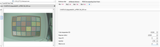
Now I'm doing AWB calibration but can't get good AWB result. For preview mode, I observe AWB is not good. I'd like to check if it is related to Black level issue.

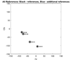
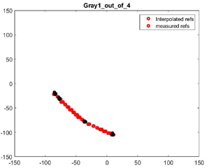
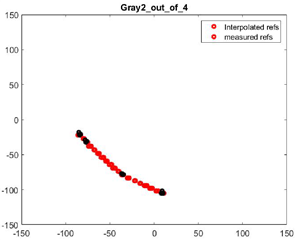
I set BL=0 while inputting raw image and get the result as below. And then I try to modify BL=1000 and it will get almost the same result as BL=0. However they output different AWB tuning parameter(IMX728_awb_alg_ti3_tuning.xml). May I know in which file I should set Black level for WDR sensor? And how should I set BL during AWB calibration?

  • Hi Taylar,

    And how should I set BL during AWB calibration?

    Please follow the AWB plugin guide under the help menu.
    In your case of WDR sensor, you should follow section "1.3.3".

    May I know in which file I should set Black level for WDR sensor?

    Please follow the black level plugin guide for this.
    As stated, the for WDR sensors, you shall not use any non-zero black level in the black level plugin.
    If there is any non-zero black level in your sensor output raw image, it is removed by the CFAI+WDR plugin output.

  • Hi Gang Hua,

    (1) As 1.3.3 mentions as below, then how I know the BL shall be removed Before or After decompanding?

    " If the raw images have a black level of 200 which shall be removed after decompanding, users shall enter the black level of 200 in the GUI along with each input raw image. If the sensor black level of 200 shall be removed before decompanding, then the first column of the knee-point file shall be adjusted to remove the black level, and the black level in GUI shall be set to 0."

    (2) For BL plugin, I input raw file which I cature in WDR mode and get BL value as below. 

    May I know if I should modify BL value for WDR mode?

    <viss_clamp_dcc type="viss_clamp">
    {
    //viss_clamp_vshort : For linear mode only this should be set to sensor Black Level
    {
    -227, // dcoffset_clamp_value 0
    -227, // dcoffset_clamp_value 1
    -227, // dcoffset_clamp_value 2
    -227, // dcoffset_clamp_value 3
    },
    //viss_clamp_short : To be used only in WDR mode.
    {
    -227, // dcoffset_clamp_value 0            -> Modify -227 to 0
    -227, // dcoffset_clamp_value 1             -> Modify -227 to 0
    -227, // dcoffset_clamp_value 2             -> Modify -227 to 0
    -227, // dcoffset_clamp_value 3              -> Modify -227 to 0
    },
    //viss_clamp_long : To be used only in WDR mode.
    {
    -227, // dcoffset_clamp_value 0             -> Modify -227 to 0
    -227, // dcoffset_clamp_value 1             -> Modify -227 to 0
    -227, // dcoffset_clamp_value 2              -> Modify -227 to 0
    -227, // dcoffset_clamp_value 3              -> Modify -227 to 0
    }
    }
    </viss_clamp_dcc>

  • For "As stated, the for WDR sensors, you shall not use any non-zero black level in the black level plugin.
    If there is any non-zero black level in your sensor output raw image, it is removed by the CFAI+WDR plugin output."

    Currently, BL value in CFAI+WDR plugin is "0". Should I modify it as -227?

  • 123.rar

    Hi Gang Hua,

    We upload the tuning project and raw image for your reference. 

    Comparing with referecne tuning parameter of IMX728, we just replace IMX728_awb_alg_ti3_tuning.xml which was generated by AWB calibration.

    And there is reddish color tinit now. Could you help to check why AWB works abnormally? We doubt it might be related to Black level for WDR mode.

  • Hi Taylar,

    then how I know the BL shall be removed Before or After decompanding?

    It is decided by your sensor settings.
    Sensor may added pedestal either before or after companding.

  • Currently, BL value in CFAI+WDR plugin is "0". Should I modify it as -227?

    You would need to check if your sensor driver has a non-zero pedestal and if it is before or after companding in sensor.
    Then, you would need to set the black level accordingly in CFAI+WDR plugin (either as a black level or modify the knee points).

    You may also use the tool below for BLC and decompanding settings if you don't feel comfortable with the GUI tool.

    https://git.ti.com/cgit/processor-sdk/imaging/tree/tools/default_DCC_profile_gen?h=main

    You would need to fill in the sensor property file correctly.

    https://git.ti.com/cgit/processor-sdk/imaging/tree/tools/default_DCC_profile_gen/configs/imx728_properties.txt?h=main

    The generated blc and decompanding xml files and LUTs can be used with your other GUI tool output.

  • And there is reddish color tinit now. Could you help to check why AWB works abnormally? We doubt it might be related to Black level for WDR mode.

    Could you please confirm your sensor settings for pedestal?

    ISP settings must match to that.

  • May I know if I should modify BL value for WDR mode?

    <viss_clamp_dcc type="viss_clamp">
    {
    //viss_clamp_vshort : For linear mode only this should be set to sensor Black Level
    {
    -227, // dcoffset_clamp_value 0
    -227, // dcoffset_clamp_value 1
    -227, // dcoffset_clamp_value 2
    -227, // dcoffset_clamp_value 3
    },
    //viss_clamp_short : To be used only in WDR mode.
    {
    -227, // dcoffset_clamp_value 0            -> Modify -227 to 0
    -227, // dcoffset_clamp_value 1             -> Modify -227 to 0
    -227, // dcoffset_clamp_value 2             -> Modify -227 to 0
    -227, // dcoffset_clamp_value 3              -> Modify -227 to 0
    },
    //viss_clamp_long : To be used only in WDR mode.
    {
    -227, // dcoffset_clamp_value 0             -> Modify -227 to 0
    -227, // dcoffset_clamp_value 1             -> Modify -227 to 0
    -227, // dcoffset_clamp_value 2              -> Modify -227 to 0
    -227, // dcoffset_clamp_value 3              -> Modify -227 to 0
    }
    }
    </viss_clamp_dcc>

    To be clear, this is wrong for your WDR senosr.

    You must use 0 for all the 12x "-227" in this file.

  • Hi Gang Hua,

    For "Could you please confirm your sensor settings for pedestal?

    ISP settings must match to that."

    Frankly speaking, now the IMX728 camera module on our hand is not formal sample. So, module maker hasn't done Black level calirantion for WDR mode. We can't get the informaiton about pedestal. Could you recommend other way to get it?

  • Hi Taylar,

    There are some registers in your sensor for setting the pedestal value.
    Please check your current sensor driver and register manual.

    BTW, we cannot discuss share sensor register details under NDA in public forum.

  • Hi Gang Hua,

    As we checked, it seems that non-zero pedestal is added before companding in sensor.

    Then how should we modify for PWL?

    WDR_KNEE_X 0,384,512,1088,1408,1952,2016,2560,2976,3040,3264,4095
    WDR_KNEE_Y 0,384,858,3250,14445,34929,59255,243067,490916,997067,4089990,16777215
  • Hi Taylar,

    As we checked, it seems that non-zero pedestal is added before companding in sensor.

    You may enter the black level in the config file.

    https://git.ti.com/cgit/processor-sdk/imaging/tree/tools/default_DCC_profile_gen/configs/imx728_properties.txt?h=main#n26

  • Hi Gang Hua,

    I have one question about the AWB calibration test result that I uploaded. According to output graph of calibration result, it seems to be OK, isn't it?

    If I used the wrong combination of PWL and Pedestal value, I can't get the normal calibration result like this. Could you let me know if my understanding is right?

  • Hi Taylar,

    Yes, AWB calibration could be fine as you input the black level in tuning tool.

    AWB may failed on H/W at run-time if black level is not set up properly in decompanding and BLC xml files.

  • Hi Gang Hua,

    I have some confusion about below test result. If default sensor setting and PWL match with default AWB tuning parameters. Why I use them to capture raw and calibrate AWB, and finally get bad AWB tuning parameters?

    (1) I used default IMX728 sensor setting + default PWL + default AWB tuning parameters -> AWB works normally

    (2) I used default IMX728 sensor setting + default PWL + calibrated AWB tuning parameters -> AWB works abnormally

    Note: calibrated AWB tuning parameters come from the raw captured by using default IMX728 sensor setting + default PWL

  • Hi Taylar,

    If default sensor setting and PWL match with default AWB tuning parameters. Why I use them to capture raw and calibrate AWB, and finally get bad AWB tuning parameters?

    For AWB to work properly on H/W, all processing stages before AWB must be set up correctly (which is not included in AWB calibration in tuning tool).

    (1) I used default IMX728 sensor setting + default PWL + default AWB tuning parameters -> AWB works normally

    What do you mean by default here (as from python script output)?

    To be clear, AWB is not calibrated by python script as of now.

    (2) I used default IMX728 sensor setting + default PWL + calibrated AWB tuning parameters -> AWB works abnormally

    This is not expected in general.
    If you start with python script as default, then add AWB calibration in tuning tool on top, AWB should work properly.
    The assumption is that AE is also set up and working properly so that VISS-H3A output provides correct input for AWB.

    Please check AWB plugin guide to see if you missed anything in the AWB calibration GUI.