This thread has been locked.

If you have a related question, please click the "Ask a related question" button in the top right corner. The newly created question will be automatically linked to this question.

AM4376: CLKOUT2 stability for Ethernet PHY clocking

Part Number: AM4376

Tool/software:

Hello Experts!


We have a strange problem with Ethernet link stability with an AM4376-based design using DP83826 PHYs.


We have a design which is basically a AM4376 with two Ethernet ports, realized with DP83826 with MII connection.
Port 1 PHY is clocked by AM4376 CLKOUT1 signal, Port 2 PHY is clocked by AM4376 CLKOUT2 signal.
AM4376 input clock is an 25MHz oscillator with +/- 50ppm.

The link is getting lost sometimes (~every 10s to every hour).

The problem occurs only, when two devices are directly connected using port 2 of each device, but not when port 1 is involved:


device#1 Port#1 connected to device#2 Port#1 is OK
device#1 Port#2 connected to device#2 Port#1 is OK
device#1 Port#1 connected to device#2 Port#2 is OK
device#1 Port#2 connected to device#2 Port#2 is not OK


A link with "itself" (connecting PHYs port2 RX to port2 TX) is also stable:

device#1 Port#2 connected to device#1 Port#2 is OK

I investigated the PHY registers, and I recognized that register 0x14 (false carrier counter) is incrementing as well as register 0x15 (receive error counter) on port#2.
At some point there are enough errors to trigger the “fast link down on RX_ER” function of the PHY.

After link loss, link is established automatically again. AN result is 100M Full duplex.

The strapping and config via MDIO are identical to both PHYs, so I looked for the differences of both ports and tried to clock both PHYs by CLKOUT1 pin.

This eliminates all errors, link is stable, no error register counting.

So, the issue seems to be “CLKOUT2”-related.

Since a PHY, clocked with CLKOUT2, has stable link with itself (TX connected to RX), it doesn´t look like clk interruptions or something similar.


My assumption is a frequency tolerance/jitter on CLKOUT2. At some time, the added tolerance/jitter of both CLKOUT2 is too large to maintain link.


CLKOUT2 is controlled by an AM4376-internal low jitter PLL (EXTDEV_PLL).

Settings:

CLKINP: 25MHz (the main osc clock input)
Divider N: 9
Multiplier M: 200
Post divider M2: 10
SD_DIV: 2

CLKOUT2 divider: 2

So, the PLL should be locked at 500MHz (25MHz / (9+1)) * 200, PLL output is 50MHz (500MHz / 10), divided by 2 in the CLKOUT2 divider gives 25MHz on CLKOUT2.
SSC is deactivated.

Register contents for EXTDEV_PLL configuration:
[0x44DF2E60] = 0x7
[0x44DF2E64] = 0x1
[0x44DF2E6C] = 0x200c809
[0x44DF2E70] = 0x38a
[0x44DF2E84] = 0x80000
[0x44DF2E88] = 0x0
[0x44DF2E8C] = 0x0


I´m really wondering about this, since in the reference manual it is explicit written that CLKOUT2 can be used to clock an external PHY.


Questions:
Did you see something like this in the past? Is there a known issue with CLKOUT2 frequency precision? Or a special sensitivity of DP83826 to CLK tolerances?
Could you please review PLL settings? Is there something to optimize (e.g. PLL lock at higher/lower frequency, try bypass mode…)?

Thank you!

Christian

  • It appears you are not using optimized PLL configuration for low jitter. The PLL output phase relationship with to the 25MHz reference clock is only checked each cycle of the pre-divided reference clock. Dividing the 25MHz reference clock by 10 is allowing the PLL output to drift too much between updates. I asked our PLL expert to reply with a PLL configuration that should result in lower jitter.

    Regards,
    Paul

  • It looks like you do have optimal configuration for your EXTDEV_PLL.  Can you also try the following, which increases the internal DCO frequency

    N=9

    M=800

    M2=40

    SD_DIV = 8

    FREQSEL_DCO = 4

    This will yield the same frequency with higher DCO (DCO freq spec is 500MHz-2GHz) and a different Sigma Delta divider, which may give you better performance.

    You can also try with bypass frequency.

    Regards,

    James

  • Thank you!

    We´ll try the suggested settings.

    I´ll come back to you with the results.

    Regards,

    Christian

  • We changed PLL settings according to your suggestion and see a significant improvement. But we still have link losses (3 within 1 week). Is there any further possibility for optimization?

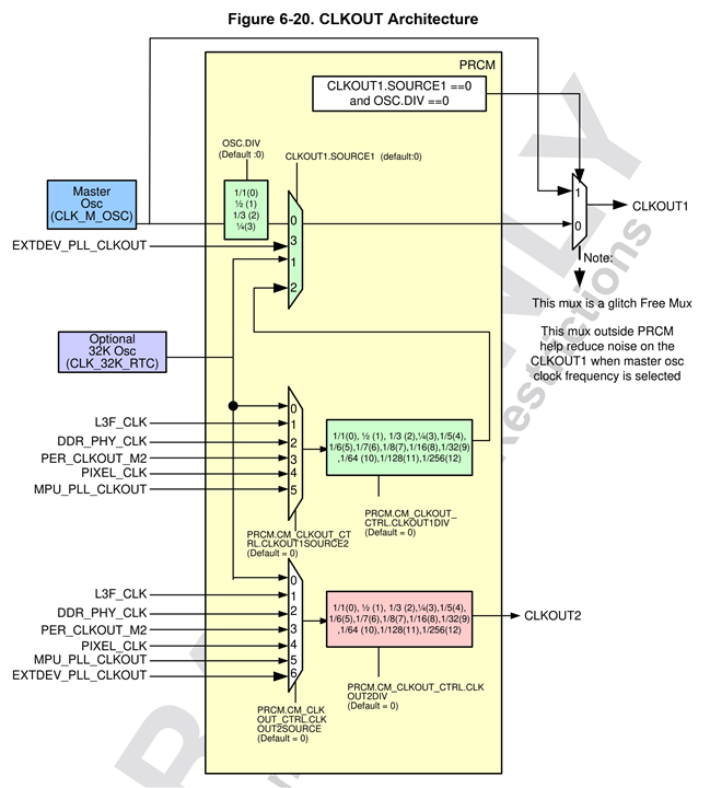
  • When you tried with CLKOUT1 and saw no errors, which PLL was the source for CLKOUT1?  Below is the clock structure in the device

    Have you tried one of the other sources for CLKOUT2.  For example, you should be able to divide down the L3F_CLK to get 25MHz.  This clock is actually sourced from a different type of PLL and may give you better performance.

    I believe that is the most optimal settings with the EXTDEV_PLL    

    Regards,

    James

  • Hi James.

    For CLKOUT1, we use "CLK_M_OSC" with division factor 1, so, the bypass around the PRCM should be used.

    I tried other sources than EXTDEV_PLL for CLKOUT2 and its getting much worse. 

    BR, Christian

  • James is out of the office until Monday. Can you provide your configuration of the Core PLL used to create L3F_CLK?  This will allow James to check if you have Core PLL configured to minimize jitter. You want to reduce the pre-divider, which increases the PLL reference clock frequency as high as possible and use a multiplier / post divider combination that operates the PLL VCO near it upper limit to achieve the lowest jitter profile from the PLL.

    I forgot the low jitter PLL implementation limits the PLL reference clock frequency. I do not think the other PLL implementation has the same reference clock frequency limitation. So please check your configuration of Core PLL to make sure it has been optimized for low jitter.

    Some Ethernet PHYs do not like the N-cycle jitter profile of the PLLs implemented in the AM437x device. If so, you may need to use a 25 MHz reference clock that is not generated from a PLL.

    You may need to connect a 1-input to 2-ouput buffer to the CLKOUT1 output and source each PHY from one of the buffer outputs.

    Regards,
    Paul

  • Hi Paul.

    Core_PLL settings: 

    N=24, M=1000, M4=10. 

    When I´m using L3F as clock source for CLKOUT2 with div=8, the result is much worse than original settings. I changed Core PLL to to:

    N=0, M=40, M4=10.

    The result is better than the test before, but still much worse compared to original settings. So the use of L3F seems to be not a good option.

    regrads,

    Christian

  • Based on this result, the jitter sensitivity of the Ethernet PHY appears to be too low for you to use any of the AM437x PLL clock sources as the PHY reference clock.

    I suggest connecting a 1-input to 2-ouput buffer to the AM437x CLKOUT1 output and source each PHY from one of the buffer outputs. You could potentially use two separate buffers, but their PCB placement needs to allow the two inputs to be located very close to each other, where the CLKOUT1 signal can be connected to each buffer input via a very short balanced-T connection topology.

    Regards,
    Paul

  • Thank you!

    We´ll consider this option. Maybe it´s a good idea to mention this weakness in the errata sheet.

    Regards,

    Christian

  • Where is the weakness in this combination of devices, is it in the AM437x device or the Ethernet PHY?

    This can occur because the Ethernet standards only define a long-term frequency error. They do not define a short-term frequency error limit. Without a short-term frequency error limitation, designers do not know how big to make elastic buffers which are used to move data from one clock domain to another clock domain. Not having a big enough elastic buffer can cause problems when the PLL in one device is running fast and the other is running slow while trying to stay locked to their respective reference clocks. This frequency error can cause the elastic buffers to under-run or over-run.

    The frequency error associated with a device connected to the other end of the Ethernet cable can also impact the issue since the Ethernet PHY is recovering a clock from the receive data stream and the receive data is transferring from the recovered clock domain to the MAC clock domain.

    We have only seen this occur once before on an older TI processor, about 15 years ago. So, the occurrence of the problem seems to very low.

    Regards,
    Paul

  • Hi Paul.

    Until now, it is not absolutely clear where the weakness in this combination is coming from, AM4376 or DP83826. We´ll definitely try with KSZ8081, since it is footprint compatible.

    You are right, this error occurs very seldom. We only see it when we connect two devices with their "CLKOUT2"-clocked PHYs directly. If we put a network switch in between, error is gone. 

    But currently we implementing new features to our device, where exactly this network topology of direct connection is used.

    Regards,

    Christian

  • Hi Paul.

    I think the DP83826 is more sensitive to clock variations than DP83822.

    I tested a very similar design with DP38822, and I cannot see any issue.

    Regards, Christian