This thread has been locked.

If you have a related question, please click the "Ask a related question" button in the top right corner. The newly created question will be automatically linked to this question.

DRA821U-Q1: SoC AC specification for OSPI operation with data Training enabled

Part Number: DRA821U-Q1

Tool/software:

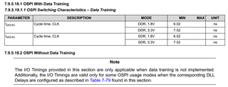
this is TI document, which does not give OSPI switching characteristics - data traning.

can you provide AC specification covering both requirements and switching characteristic ?

Thanks 

  • Hello Max,

    I had to re-assign your thread. Please expect a little bit of additional delay on response.

    -Josue

  • Hi Max,

    Table 6-107 OSPI Switching Characteristics – PHY Data TrainingSee Figure 6-90 and Figure 6-91

    NO.

    PARAMETER


    MODE

    MIN

    MAX

    UNIT

    O1

    tc(CLK)

    Cycle time, OSPI0/1_CLK

    1.8V, DDR

    6.0

    6.0

    ns

    O7


    1.8V, SDR

    6.0

    6.0

    ns

    O2

    tw(CLKL)

    Pulse duration, OSPI0/1_CLK low

    DDR

    ((0.475P(1)) - 0.3)


    ns

    O8


    SDR


    O3

    tw(CLKH)

    Pulse duration, OSPI0/1_CLK high

    DDR

    ((0.475P(1)) - 0.3)


    ns

    O9


    SDR


    O4

    td(CSn-CLK)

    Delay time, OSPI0/1_CSn[3:0] active edge to OSPI0/1_CLK rising edge

    DDR

    ((0.475P(1)) + (0.975M(2)R(4)) + (0.028TD(5)) - 1)

    ((0.525P(1)) + (1.025M(2)R(4)) + (0.055TD(5)) + 1)

    ns

    O10


    SDR


    O5

    td(CLK-CSn)

    Delay time, OSPI0/1_CLK rising edge to OSPI0/1_CSn[3:0] inactive edge

    DDR

    ((0.475P(1)) + (0.975N(3)R(4)) - (0.028TD(5)) - 1)

    ((0.525vP(1)) + (1.025N(3)R(4)) - (0.055TD(5)) + 1)

    ns

    O11


    SDR


    O6

    td(CLK-D)

    Delay time, OSPI0/1_CLK active edge to OSPI0/1_D[7:0] transition

    DDR

    (6)

    (6)

    ns

    O12


    SDR


    tDIVW

     (O6 Max - Min)

    DDR


    1

    ns


     (O12 Max - Min)

    SDR


    (1) P = SCLK cycle time in ns = OSPI0/1_CLK cycle time in ns

    (2) M = OSPI_DEV_DELAY_REG[D_INIT_FLD]

    (3) N = OSPI_DEV_DELAY_REG[D_AFTER_FLD]

    (4) R = reference clock cycle time in ns

    (5) TD = PHY_CONFIG_TX_DLL_DELAY_FLD

    (6) Minimum and maximum delay times for OSPI0/1_D[7:0] outputs are not defined when Data Training is used to find the optimum data valid window. The tDIVW parameter defines the maximum data invalid window. This parameter is provided in lieu of minimum and maximum delay times, where it must be used to check compatibility with the data valid window requirements of an attached device.

    These will be updated in the newest revision of the datasheet. For now, I have attached the timing requirements and switching characteristics for you here. 

    Best Regards,

    Matt