This thread has been locked.

If you have a related question, please click the "Ask a related question" button in the top right corner. The newly created question will be automatically linked to this question.

AM625: AM625 GPMC trace length and mismatch

Part Number: AM625

Tool/software:

Dear Champ, 

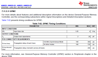
On AM625 Data Manual GPMC timing conditions table, it indicates PCB CONNECTIVITY REQUIREMENTS. 

For Td (trace delay), Propagation delay of each trace, for 133Mhz, Min 140 ps and Max 360 ps. 

Is this characteristic for PCB it self which the stackup and layout trace propagation delay need to within the range? 

Is not ruling the delay create by the total trace length, right? 

Next parameter Td(Trace Mismatch Delay), Max 200 ps, what's the definition of Mismatch? 

Mismatch between each signal trace length? 200ps could be 1000mil difference on trace length. 

I think the mismatch here should not be the trace length difference. 

Is the characteristic for PCB layout trace equivalent propagation delay based on its stack and trace width and reference layer?  

The last, is there trace length limitation for GPMC? 

BR, Rich 

  • Hello Rich,

    Thank you for the query.

    The last, is there trace length limitation for GPMC? 

    The delay of the trace indirectly limits the length.

    Let me check with the experts and comeback.

    Regards,

    Sreenivasa

  • Sreenivasa,

    Do we have update for this?

    BR, Rich 

  • Hello Rich,

    I assigned the query to the expert.

    Regards,

    Sreenivasa

  • Hello Rich,

    The PCB CONNECTIVITY REQUIREMENTS in the GPMC Timing Conditions table
     - td(Trace Delay) Propagation delay of each trace
     - td(Trace Mismatch Delay) Propagation delay mismatch across all traces
    are the assumptions we used in the timing analysis when deciding the boundaries of timing requirements and switching characteristics.
    For example, we needed to place the memory devices that support 133MHz closer to the SoC pins for the timing analysis to provide positive read setup time margin. This distance gets used as round trip delay (PCB delay of CLK from SoC to Memory + PCB delay of Data from Memory to SoC)
    * Maximum round trip delay for setup time - during reads, the latching CLK is not delayed by any trace length, but the data from the memory cannot become valid until the CLK propagates from the SoC to the memory and then the data propagates from the memory to the SoC). Setup time margins are reduced the farther away the memory is from the SoC.
    * Minimum round trip delay for hold time - during reads, a memory that is farther away means that the data remains valid on the bus longer after the latching CLK edge - adding hold time.
    * Another factor in this analysis is the output delay of the memory from CLK edge to data valid - if that delay is less then there is more margin for the signal to propagate across the PCB

    td(Trace Delay) does mean the PCB trace delay or roughly (length of trace) * (160ps per inch or 18ps per inch)

    td(Trace Mismatch Delay) gets used as a bound on the worst mismatch between CLK and data. The mismatch is subtracted from the timing analysis for setup time at the memory to cover the case where the clk takes a shorter path and arrives at the memory before the data. If all data and CLK are bound within the td(Trace Mismatch Delay), then this captures the worst mismatch between any data and CLK.

    In above examples, I used CLK and data. Similar synchronous timing analysis also applies to CLK and addr, CLK and control (CS, WE, OE, etc.)

    Asynchronous modes offer more flexibility with regard to controlling when bus signals (CS, WE, OE, ADV) are driven and when the data is latched. Timings can be relaxed to allow for all signals to propagate and become valid.

    If the customer performs their own timing analysis with another device, it is possible to violate the PCB connectivity requirements in the GPMC Timing Conditions. it is not recommended to violate Input slew rate limits or the Output load capacitance limits.

    The trace length limitation will be found by performing timing analysis.

    Regards,
    Mark