This thread has been locked.

If you have a related question, please click the "Ask a related question" button in the top right corner. The newly created question will be automatically linked to this question.

SK-AM62P-LP: Enable CC256XEM-STADAPT and CC256xOFN-EM module on AM62P

Part Number: SK-AM62P-LP
Other Parts Discussed in Thread: AM62P, CC2564, AM625

Tool/software:

Dear Team,

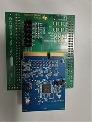
We are working on Android Automotive v14.0 on SK-AM62P-LP. In order to enable classic BT for uses cases such as Bluetooth Audio/Telephony we need to enable CC256XEM-STADAPT and CC256xOFN-EM module.

But default, the Bluetooth is not enabled. We also need to understand how to connect the same with  AM62P.

Kindly support us in bringing up this module on AM62P. We are currently working on customer project and it is very important to enable this module.

Best regards,

Libin Jose

  • Hi Libin,

    In order to use the CC2564 on a linux processor you will need configure your device tree properly.

    Here is an example device tree that uses the AM62SK dts. Your dts should be similar however the UART pins might differ as the AM62P is a different device

    https://e2e.ti.com/cfs-file/__key/communityserver-discussions-components-files/791/0245.k3_2D00_am625_2D00_sk.dts

    This is where the UART pins get chosen in the dts.

    You will also need a bt enable pin configured in the dts

    This is where you tell the dts that the UART will be used for the CC2564.

    If you plan on using any audio you will also need to route the audio pins to an audio card to your dts.

    Best,

    Rogelio

  • Dear Rogelio,

    SW: Android Automotive v14, Version: 10.00.00

    HW: AM62P

    I am sorry, we are not experts in Linux DTS configuration. Anyways, we can follow.

    I would request to take this step by step:

    1. Connection

    2. Modifying DTS

    3. Enabling BT stack

    4. Testing via application

    So lets discuss about CONNECTION first. Please find the image below

    Ball number

    Address

    GPIO PIN (MCU header)

    Connection

    G23

    0x1AC

    13

    RXD

    G20

    0x1B0

    14

    TXD

    E25

    0x198

    8

    RTS

    D25

    0x194

    7

    CTS

    364     main_uart1_pins_default: main-uart1-default-pins {                                              
    365         pinctrl-single,pins = <                                                                     
    366             AM62PX_IOPAD(0x0194, PIN_INPUT, 2) /* (D25) MCASP0_AXR3.UART1_CTSn */                   
    367             AM62PX_IOPAD(0x0198, PIN_OUTPUT, 2) /* (E25) MCASP0_AXR2.UART1_RTSn */                  
    368             AM62PX_IOPAD(0x01ac, PIN_INPUT, 2) /* (G23) MCASP0_AFSR.UART1_RXD */                    
    369             AM62PX_IOPAD(0x01b0, PIN_OUTPUT, 2) /* (G20) MCASP0_ACLKR.UART1_TXD */                  
    370         >;                                                                                          
    371         bootph-all;                                                                                 
    372     };                                                                                              
    373     

    Below is my addition:

    diff --git a/arch/arm64/boot/dts/ti/k3-am62p5-sk.dts b/arch/arm64/boot/dts/ti/k3-am62p5-sk.dts
    index dd9662d65..3f698f288 100644
    --- a/arch/arm64/boot/dts/ti/k3-am62p5-sk.dts
    +++ b/arch/arm64/boot/dts/ti/k3-am62p5-sk.dts
    @@ -371,6 +371,12 @@
                    bootph-all;
            };
     
    +    main_bt_pins_deafult: main-bt-en-pins-default {
    +               pinctrl-single,pins = <
    +                       AM62PX_IOPAD(0x019c, PIN_OUTPUT, 7) /* (E24) MCASP0_AXR1.GPIO1_9 */
    +               >;
    +       };
    +
            main_usb1_pins_default: main-usb1-default-pins {
                    pinctrl-single,pins = <
                            AM62PX_IOPAD(0x0258, PIN_INPUT, 0) /* (G21) USB1_DRVVBUS */
    @@ -807,11 +813,14 @@
     };
     
     &main_uart1 {
    +       status = "okay";
            pinctrl-names = "default";
    -       pinctrl-0 = <&main_uart1_pins_default>;
    -       /* Main UART1 is used by TIFS firmware */
    -       status = "reserved";
    -       bootph-all;
    +       pinctrl-0 = <&main_uart1_pins_default &main_bt_pins_deafult>;
    +
    +       bluetooth {
    +               compatible = "ti,cc2560";
    +               enable-gpios = <&main_gpio0 9 GPIO_ACTIVE_HIGH>;
    +       };
     };
     
     &mcu_pmx0 {

    1. Where to connect the power and ground for the adapter? Is it GPIO1_9? Which PIN in adapter should be used as ground? 

    After you confirm PIN settings, DTS and power connection, lets move to next step. Okay?

    Best regards,

    Libin Jose

  • Hi Libin,

    is there a particular reason you want to use the ST adapter board?. That board is specifically created to route all the needed lines from the ST board to the CC256x EVM RF connectors. However since you are using an am62, theres no reason to use it, as it just adds a middle layer of confusion.

    Here are the schematics for the evm.

    CC256xCQFN-EM_Schematic_10182016.pdf

    In Regards, to power and ground. The EVM needs to be powered by 3.3V and the ground would connect to the ground on the am62 evm.

    Here is the am62 schematic.

    sprr487b.zip

    Once you have the UART connection the BLE_enable pin and ground pin and 3.3V power pin routed correctly we can move on to the next step. In verifying the connection.

    Best,

    Rogelio

  • Dear Rogelio,

    >> is there a particular reason you want to use the ST adapter board?.

    No, it was actually recommended by TI when we had a discussion to enable BT.

    However, we have now changed it to use the chip independently. See picture below.

    We mapped the connection setup like above. Could you please confirm?

    User Expansion connector(j4):https://www.ti.com/lit/ug/spruja2/spruja2.pdf

    Pin Attributes: https://www.ti.com/lit/ds/symlink/am62p.pdf?ts=1746422064230

    1. If the connection is right, could you verify if the DTS patch is right? Can kernel log confirm it?

    2. What will be device name (serial port) /dev/ttyS0? How do we confirm the device name?


    Best regards,

    Libin Jose.

  • Hi Libin,

    I apologize for the delay here, I have gone over the schematics and dts file and have the following comments.

    The dts file uart lines and enable line seems configures correctly. However be aware that you might have to populate r214 and depopulate r216 if it hasnt been done on your board.

    This is because the UART1_FET_SEL  needs to be LOW to select the expansion connector. By default it is high.

    You will also need to make sure to add the UART1_FET_BUF_EN to be high. This is done also in the dts file.

    Once you have those additions you should be able to wire up the CC2564 and am62. From there the device should load the bluetooth fw with the hcill driver. You can confirm it is working  by calling hciconfig hci0 -a and see there is an hci0.

    Best,

    Rogelio

  • Dear ,

    >>However be aware that you might have to populate r214 and depopulate r216 if it hasn't been done on your board.

    How do I execute the above step (OR) is it also done using DTS file? 

    >> You will also need to make sure to add the UART1_FET_BUF_EN to be high. This is done also in the dts file.

    Can you give us some example?

    The current status in our environment is as follows

    <<Other info>>>

     dmesg | grep Bluetooth                                                                                                                                                                   
    [    6.590570] Bluetooth: Core ver 2.22
    [    6.590681] Bluetooth: HCI device and connection manager initialized
    [    6.590699] Bluetooth: HCI socket layer initialized
    [    6.590709] Bluetooth: L2CAP socket layer initialized
    [    6.590730] Bluetooth: SCO socket layer initialized
    

    root@am62pxx-evm:~# gpioset -c gpiochip3 6=1 &
    [1] 1632
    root@am62pxx-evm:~# 
    root@am62pxx-evm:~# gpioset -c gpiochip3 2=0 &
    [2] 1633
    

    root@am62pxx-evm:~# gpioinfo -c gpiochip3                                                                                                                                                               
    gpiochip3 - 24 lines:
            line   2:       "UART1_FET_SEL"         output consumer="gpioset"
            line   6:       "UART1_FET_BUF_EN"      output consumer="gpioset"
    

    root@am62pxx-evm:~# hciconfig hci0 -a
    Can't get device info: No such device
    root@am62pxx-evm:~# hciconfig        
    root@am62pxx-evm:~# 
    

    Best regards,

    Libin Jose

  • Hi Libin,

    From the Schematic I see that FET Select is either pullled high or low with physical resistors. You would need to desolder r214 which is pulling the line to ground, and populate resistor r216 to make it high.

    in regards to the FET Enable it seems as though by default it is active high 

    Best,

    Rogelio

  • Dear ,

    Please find the attached image. From visual inspection of the evaluation board, it seems that R214 is by default depopulated and r216 is populated. So we believe, there is no change required at hardware level. Could you verify that our understanding is right?

    Best regards,

    Libin Jose

  • Hi Libin,

    Thank you for verifying the r214 is indeed depopulated and r216 is populated. I think you may have gotten mixed up, but that means that you will have to remove the resistor from r216 and place it on r214

    This will pull the FET SEL to LOW which is what you want to select the expansion header

    Best,

    Rogelio