This thread has been locked.

If you have a related question, please click the "Ask a related question" button in the top right corner. The newly created question will be automatically linked to this question.

AM623: I2C duty cycle doesn't follow TRM

Part Number: AM623

Tool/software:

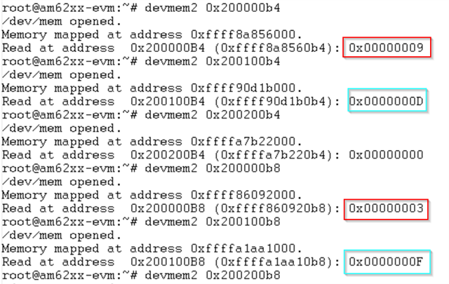
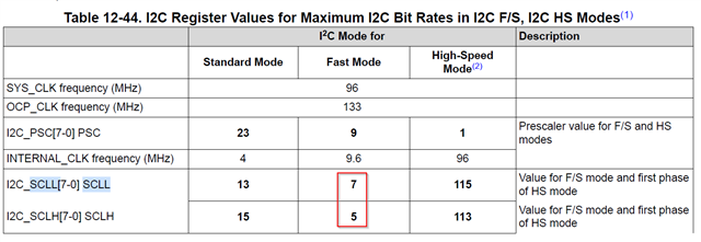
According to TRM, in 400KHz fast mode, SCLL=7, SCLH=5, but read back register SCLL=9, SCLH=3. From SDK8.3 and SDK9.2.

While standard 100KHz configuration is same as TRM.

In SDK11.0, configured I2C2 to fast mode with wrong value also.
root@am62xx-evm:~# devmem2 0x200000b4
/dev/mem opened.
Memory mapped at address 0xffffa9bb3000.
Read at address 0x200000B4 (0xffffa9bb30b4): 0x00000009
root@am62xx-evm:~# devmem2 0x200100b4
/dev/mem opened.
Memory mapped at address 0xffff89f3d000.
Read at address 0x200100B4 (0xffff89f3d0b4): 0x0000000D
root@am62xx-evm:~# devmem2 0x200200b4
/dev/mem opened.
Memory mapped at address 0xffffbef3a000.
Read at address 0x200200B4 (0xffffbef3a0b4): 0x00000009
root@am62xx-evm:~#
root@am62xx-evm:~# devmem2 0x200000b8
/dev/mem opened.
Memory mapped at address 0xffffb340d000.
Read at address 0x200000B8 (0xffffb340d0b8): 0x00000003
root@am62xx-evm:~# devmem2 0x200100b8
/dev/mem opened.
Memory mapped at address 0xffff840d5000.
Read at address 0x200100B8 (0xffff840d50b8): 0x0000000F
root@am62xx-evm:~# devmem2 0x200200b8
/dev/mem opened.
Memory mapped at address 0xffffb30b8000.
Read at address 0x200200B8 (0xffffb30b80b8): 0x00000003
root@am62xx-evm:~#

  • Hello Tony,

    Was there specific behavior that caused the customer to start looking into the I2C clock settings?

    Could we get you or the customer to capture the I2C waveforms with an oscilloscope and measure
    1) the actual frequency that is getting output (please check multiple pulses, not just one)
    2) the width of the high part of the pulse as opposed to the low part of the pulse?

    Please include information like if this is a TI EVM, which revision of the EVM, which I2C port is being measured, etc.

    We are actually in the middle of debugging the relationship between the actual measured I2C frequency and the SCLL / SCLH settings for another customer (sometimes there might be an extra clock or couple of clocks getting added to the low or high part of the pulse, making the clock pulse slightly longer than a 400kHz clock). We are still early in that investigation process, so it would be good to get another datapoint from your side.

    Additional thoughts 

    The pulse width of the I2C clock is based on the number of clock cycles for the Low part of the pulse (SCLL), and the number of clock cycles for the High part of the pulse (SCLH). 7 + 5 = 12, and 9 + 3 = 12, so theoretically we should still see a 400kHz clock with your observed settings. The low part of the clock would just be much longer than the high part of the clock.

    Regards,

    Nick

  • Hello Tony,

    Thank you for sending the questions and waveform offline.

    Summary 

    The waveform you sent confirms that the code is behaving exactly the way we would expect.

    Where is this SCLL / SCLH value of 9 / 3 coming from? 

    Here is the part of the I2C driver that is doing the calculations. I have added comments to show the math:

    drivers/i2c/busses$ vi i2c-omap.c

    static int omap_i2c_init(struct omap_i2c_dev *omap)
    {
    …
        else if (omap->speed > 100)
                            internal_clk = 9600;
    …
        else if (omap->speed > 100) {
                            unsigned long scl;
    
                            /* Fast mode */
                            scl = internal_clk / omap->speed; // 9600 / 400 = 24
                            fsscll = scl - (scl / 3) - 7; // 24 – (24/3) – 7 = 24 -15 = 9
                            fssclh = (scl / 3) - 5; // (24/3)-5 = 8 -5 = 3
    

    And here is the commit message where all the math was added back in 2009:
    https://git.kernel.org/pub/scm/linux/kernel/git/stable/linux.git/commit/drivers/i2c/busses/i2c-omap.c?h=v6.12.25&id=baf46b4e378d7950dff7ba30cfd50ff585987cb4

    A quick side story 

    Now wait a minute, this commit is for OMAP2/3, not AM335x. And it was written by someone from Nokia... What is going on here?

    The i2c-omap driver was originally written for a processor called OMAP1. We took the same I2C circuit design, made some minor changes, and used the same I2C circuit design for OMAP2, 3, 4, 5, and then AM335x, AM437x, etc, all the way to AM62x. Every time a new processor came out that used the same I2C design, the Linux community simply updated the i2c-omap driver so that it could be used for the new processor. Most of this code actually came from members of the Linux community outside of TI. Many Linux drivers are like this - just because TI produced the processor, does not mean that we control everything about the Linux driver.

    So even though this code was originally written for much older processors, it SHOULD still work on AM62x. We can double-check that with the waveform you sent me.

    Ok, let's double-check that the code is actually working 

    If the math in the commit is correct, we would expect to see
    tLow  = (scll + 7) * internal_clk = (9 + 7) * 9,600,000 Hz = 16 / 9,600,000 = 1.667 usec
    tHigh = (sclh + 5) * internal_clk = (3 + 5) * 9,600,000 Hz = 8 / 9,600,000 = 833 nsec

    And the average widths of the waveform you shared with me match:
    an average low width of 1.6795 usec, and an average high width of 658 ns. So the equation for OMAP2/3 still works for AM62x.

    It looks to me like your rise time is within the I2C spec of 20-300 nsec. However, if you want one of our team members to comment, I can reassign this thread to a member of the hardware team.

    Regards,

    Nick

  • Hi Nick,

    Thank you very much for explain the history clearly.

    Although the register configuration doesn't follow TRM, the waveform still meets I2C standard requirements, so it works for AM62x.

    But customer think the margin is insufficient, Is it recommended to update to TRM value? 

    Many Linux drivers are like this - just because TI produced the processor, does not mean that we control everything about the Linux driver.

    TI should maintain device specific driver, how do you think if need to file a Jira about this?

  • Hello Tony,

    Is 7/5 better than 9/3?

    If we switched to using the TRM suggestion, then I would expect the waveforms to look like
    tLow  = (scll + 7) * internal_clk = (7 + 7) * 9,600,000 Hz = 14 / 9,600,000 = 1.46 usec
    tHigh = (sclh + 5) * internal_clk = (5 + 5) * 9,600,000 Hz = 10 / 9,600,000 = 1.04 usec

    So either combination would fit the I2C spec. I double-checked with the HW owner, they do not think there is a specific reason that the customer should use one or the other. If the customer prefers to use 7 and 5, they can modify their I2C driver code.

    Do we need to file a bug against the I2C driver? 

    No. There is nothing wrong with how the driver is operating. That is one of the benefits of the Linux community, that if someone else in the world discovers a bug, they can fix it for us. That also means that the rest of the community helps to test and maintain the code that we use. We can chat more offline if you would like.

    Regards,

    Nick