This thread has been locked.

If you have a related question, please click the "Ask a related question" button in the top right corner. The newly created question will be automatically linked to this question.

TDA4VM: How to enable the Ethernet CPSW2G PHY and implement the TFTP function in U-Boot?

Part Number: TDA4VM

Tool/software:

我们使用 TDA4VM SDK 10.0,希望启用 CPSW2G 以太网在 Uboot 中实现 TFTP。
我修改了设备树。
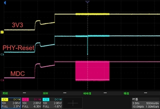
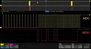
在进入 phy_find_by_mask() 函数之前,我确认了 phy 芯片的电源是正确的,并且还进行了硬件重置。PHY 地址为 2。
但我找不到我的 phy。如何调试它?
设备树和日志在此处提供:

board-support/ti-u-boot-2024.04+git/arch/arm/dts/k3-j721e-common-proc-board.dts


// SPDX-License-Identifier: GPL-2.0
/*
 * Copyright (C) 2019 Texas Instruments Incorporated - https://www.ti.com/
 *
 * Product Link: https://www.ti.com/tool/J721EXCPXEVM
 */

/dts-v1/;

#include "k3-j721e-som-p0.dtsi"
#include <dt-bindings/gpio/gpio.h>
#include <dt-bindings/input/input.h>
#include <dt-bindings/net/ti-dp83867.h>
#include <dt-bindings/phy/phy-cadence.h>

/ {
	compatible = "ti,j721e-evm", "ti,j721e";
	model = "Texas Instruments J721e EVM";

	aliases {
		serial0 = &wkup_uart0;
		serial1 = &mcu_uart0;
		serial2 = &main_uart0;
		serial3 = &main_uart1;
		serial4 = &main_uart2;
		serial6 = &main_uart4;
		ethernet0 = &cpsw_port1;
		mmc0 = &main_sdhci0;
		mmc1 = &main_sdhci1;
	};

	chosen {
		stdout-path = "serial2:115200n8";
		bootargs = "console=ttyS2,115200n8 earlycon=ns16550a,mmio32,0x02800000";
	};

	/delete-node/ gpio-regulator-TLV71033;

	gpio_keys: gpio-keys {
		compatible = "gpio-keys";
		autorepeat;
		pinctrl-names = "default";
		pinctrl-0 = <&sw10_button_pins_default>, <&sw11_button_pins_default>;

		sw10: switch-10 {
			label = "GPIO Key USER1";
			linux,code = <BTN_0>;
			gpios = <&main_gpio0 0 GPIO_ACTIVE_LOW>;
		};

		sw11: switch-11 {
			label = "GPIO Key USER2";
			linux,code = <BTN_1>;
			gpios = <&wkup_gpio0 7 GPIO_ACTIVE_LOW>;
		};
	};

	evm_12v0: fixedregulator-evm12v0 {
		/* main supply */
		compatible = "regulator-fixed";
		regulator-name = "evm_12v0";
		regulator-min-microvolt = <12000000>;
		regulator-max-microvolt = <12000000>;
		regulator-always-on;
		regulator-boot-on;
	};

	vsys_3v3: fixedregulator-vsys3v3 {
		/* Output of LMS140 */
		compatible = "regulator-fixed";
		regulator-name = "vsys_3v3";
		regulator-min-microvolt = <3300000>;
		regulator-max-microvolt = <3300000>;
		vin-supply = <&evm_12v0>;
		regulator-always-on;
		regulator-boot-on;
	};

	vsys_5v0: fixedregulator-vsys5v0 {
		/* Output of LM5140 */
		compatible = "regulator-fixed";
		regulator-name = "vsys_5v0";
		regulator-min-microvolt = <5000000>;
		regulator-max-microvolt = <5000000>;
		vin-supply = <&evm_12v0>;
		regulator-always-on;
		regulator-boot-on;
	};

	vdd_mmc1: fixedregulator-sd {
		compatible = "regulator-fixed";
		regulator-name = "vdd_mmc1";
		regulator-min-microvolt = <3300000>;
		regulator-max-microvolt = <3300000>;
		regulator-boot-on;
		enable-active-high;
		vin-supply = <&vsys_3v3>;
		//gpio = <&exp2 2 GPIO_ACTIVE_HIGH>;
	};

	vdd_sd_dv_alt: gpio-regulator-tps659411  {
		compatible = "regulator-gpio";
		pinctrl-names = "default";
		pinctrl-0 = <&vdd_sd_dv_alt_pins_default>;
		regulator-name = "vdd_sd_dv";
		regulator-min-microvolt = <1800000>;
		regulator-max-microvolt = <3300000>;
		regulator-boot-on;
		vin-supply = <&vsys_3v3>;
		gpios = <&main_gpio0 111 GPIO_ACTIVE_HIGH>;
		states = <1800000 0x0>,
			 <3300000 0x1>;
	};

	sound0: sound-0 {
		compatible = "ti,j721e-cpb-audio";
		model = "j721e-cpb";

		ti,cpb-mcasp = <&mcasp10>;
		ti,cpb-codec = <&pcm3168a_1>;

		clocks = <&k3_clks 184 1>,
			 <&k3_clks 184 2>, <&k3_clks 184 4>,
			 <&k3_clks 157 371>,
			 <&k3_clks 157 400>, <&k3_clks 157 401>;
		clock-names = "cpb-mcasp-auxclk",
			      "cpb-mcasp-auxclk-48000", "cpb-mcasp-auxclk-44100",
			      "cpb-codec-scki",
			      "cpb-codec-scki-48000", "cpb-codec-scki-44100";
	};

	transceiver1: can-phy0 {
		compatible = "ti,tcan1043";
		#phy-cells = <0>;
		max-bitrate = <5000000>;
		pinctrl-names = "default";
		pinctrl-0 = <&mcu_mcan0_gpio_pins_default>;
		standby-gpios = <&wkup_gpio0 54 GPIO_ACTIVE_LOW>;
		enable-gpios = <&wkup_gpio0 0 GPIO_ACTIVE_HIGH>;
	};

	transceiver2: can-phy1 {
		compatible = "ti,tcan1042";
		#phy-cells = <0>;
		max-bitrate = <5000000>;
		pinctrl-names = "default";
		pinctrl-0 = <&mcu_mcan1_gpio_pins_default>;
		standby-gpios = <&wkup_gpio0 2 GPIO_ACTIVE_HIGH>;
	};

	transceiver3: can-phy2 {
		compatible = "ti,tcan1043";
		#phy-cells = <0>;
		max-bitrate = <5000000>;
		standby-gpios = <&exp2 7 GPIO_ACTIVE_LOW>;
		enable-gpios = <&exp2 6 GPIO_ACTIVE_HIGH>;
	};

	transceiver4: can-phy3 {
		compatible = "ti,tcan1042";
		#phy-cells = <0>;
		max-bitrate = <5000000>;
		pinctrl-names = "default";
		pinctrl-0 = <&main_mcan2_gpio_pins_default>;
		standby-gpios = <&main_gpio0 127 GPIO_ACTIVE_HIGH>;
	};

	dp_pwr_3v3: regulator-dp-pwr {
		compatible = "regulator-fixed";
		regulator-name = "dp-pwr";
		regulator-min-microvolt = <3300000>;
		regulator-max-microvolt = <3300000>;
		gpio = <&exp4 0 GPIO_ACTIVE_HIGH>; /* P0 - DP0_PWR_SW_EN */
		enable-active-high;
	};

	dp0: connector {
		compatible = "dp-connector";
		label = "DP0";
		type = "full-size";
		dp-pwr-supply = <&dp_pwr_3v3>;

		port {
			dp_connector_in: endpoint {
				remote-endpoint = <&dp0_out>;
			};
		};
	};
};

&main_pmx0 {
	main_uart0_pins_default: main-uart0-default-pins {
		pinctrl-single,pins = <
			J721E_IOPAD(0x1f0, PIN_INPUT, 0) /* (AC2) UART0_CTSn */
			J721E_IOPAD(0x1f4, PIN_OUTPUT, 0) /* (AB1) UART0_RTSn */
			J721E_IOPAD(0x1e8, PIN_INPUT, 0) /* (AB2) UART0_RXD */
			J721E_IOPAD(0x1ec, PIN_OUTPUT, 0) /* (AB3) UART0_TXD */
		>;
	};

	main_uart1_pins_default: main-uart1-default-pins {
		pinctrl-single,pins = <
			J721E_IOPAD(0x1f8, PIN_INPUT, 0) /* (AA4) UART1_RXD */
			J721E_IOPAD(0x1fc, PIN_OUTPUT, 0) /* (AB4) UART1_TXD */
		>;
	};

	main_uart2_pins_default: main-uart2-default-pins {
		pinctrl-single,pins = <
			J721E_IOPAD(0x1dc, PIN_INPUT, 3) /* (Y1) SPI1_CLK.UART2_RXD */
			J721E_IOPAD(0x1e0, PIN_OUTPUT, 3) /* (Y5) SPI1_D0.UART2_TXD */
		>;
	};

	main_uart4_pins_default: main-uart4-default-pins {
		pinctrl-single,pins = <
			J721E_IOPAD(0x190, PIN_INPUT, 1) /* (W23) RGMII6_TD3.UART4_RXD */
			J721E_IOPAD(0x194, PIN_OUTPUT, 1) /* (W28) RGMII6_TD2.UART4_TXD */
		>;
	};

	sw10_button_pins_default: sw10-button-default-pins {
		pinctrl-single,pins = <
			J721E_IOPAD(0x0, PIN_INPUT, 7) /* (AC18) EXTINTn.GPIO0_0 */
		>;
	};

	main_mmc1_pins_default: main-mmc1-default-pins {
		pinctrl-single,pins = <
			J721E_IOPAD(0x254, PIN_INPUT, 0) /* (R29) MMC1_CMD */
			J721E_IOPAD(0x250, PIN_INPUT, 0) /* (P25) MMC1_CLK */
			J721E_IOPAD(0x2ac, PIN_INPUT, 0) /* (P25) MMC1_CLKLB */
			J721E_IOPAD(0x24c, PIN_INPUT, 0) /* (R24) MMC1_DAT0 */
			J721E_IOPAD(0x248, PIN_INPUT, 0) /* (P24) MMC1_DAT1 */
			J721E_IOPAD(0x244, PIN_INPUT, 0) /* (R25) MMC1_DAT2 */
			J721E_IOPAD(0x240, PIN_INPUT, 0) /* (R26) MMC1_DAT3 */
			J721E_IOPAD(0x258, PIN_INPUT, 0) /* (P23) MMC1_SDCD */
			J721E_IOPAD(0x25c, PIN_INPUT, 0) /* (R28) MMC1_SDWP */
		>;
	};

	vdd_sd_dv_alt_pins_default: vdd-sd-dv-alt-default-pins {
		pinctrl-single,pins = <
			J721E_IOPAD(0x1c0, PIN_OUTPUT, 7) /* (AA2) GPIO0_111 */
		>;
	};

	main_usbss0_pins_default: main-usbss0-default-pins {
		pinctrl-single,pins = <
			J721E_IOPAD(0x290, PIN_OUTPUT, 0) /* (U6) USB0_DRVVBUS */
			J721E_IOPAD(0x210, PIN_INPUT, 7) /* (W3) MCAN1_RX.GPIO1_3 */
		>;
	};

	main_usbss1_pins_default: main-usbss1-default-pins {
		pinctrl-single,pins = <
			J721E_IOPAD(0x214, PIN_OUTPUT, 4) /* (V4) MCAN1_TX.USB1_DRVVBUS */
		>;
	};

	dp0_pins_default: dp0-default-pins {
		pinctrl-single,pins = <
			J721E_IOPAD(0x1c4, PIN_INPUT, 5) /* SPI0_CS1.DP0_HPD */
		>;
	};

	main_i2c1_exp4_pins_default: main-i2c1-exp4-default-pins {
		pinctrl-single,pins = <
			J721E_IOPAD(0x230, PIN_INPUT, 7) /* (U2) ECAP0_IN_APWM_OUT.GPIO1_11 */
		>;
	};

	main_i2c0_pins_default: main-i2c0-default-pins {
		pinctrl-single,pins = <
			J721E_IOPAD(0x220, PIN_INPUT_PULLUP, 0) /* (AC5) I2C0_SCL */
			J721E_IOPAD(0x224, PIN_INPUT_PULLUP, 0) /* (AA5) I2C0_SDA */
		>;
	};

	main_i2c1_pins_default: main-i2c1-default-pins {
		pinctrl-single,pins = <
			J721E_IOPAD(0x228, PIN_INPUT_PULLUP, 0) /* (Y6) I2C1_SCL */
			J721E_IOPAD(0x22c, PIN_INPUT_PULLUP, 0) /* (AA6) I2C1_SDA */
		>;
	};

	main_i2c3_pins_default: main-i2c3-default-pins {
		pinctrl-single,pins = <
			J721E_IOPAD(0x270, PIN_INPUT_PULLUP, 4) /* (T26) MMC2_CLK.I2C3_SCL */
			J721E_IOPAD(0x274, PIN_INPUT_PULLUP, 4) /* (T25) MMC2_CMD.I2C3_SDA */
		>;
	};

	main_i2c6_pins_default: main-i2c6-default-pins {
		pinctrl-single,pins = <
			J721E_IOPAD(0x1d0, PIN_INPUT_PULLUP, 2) /* (AA3) SPI0_D1.I2C6_SCL */
			J721E_IOPAD(0x1e4, PIN_INPUT_PULLUP, 2) /* (Y2) SPI1_D1.I2C6_SDA */
		>;
	};

	mcasp10_pins_default: mcasp10-default-pins {
		pinctrl-single,pins = <
			J721E_IOPAD(0x158, PIN_OUTPUT_PULLDOWN, 12) /* (U23) RGMII5_TX_CTL.MCASP10_ACLKX */
			J721E_IOPAD(0x15c, PIN_OUTPUT_PULLDOWN, 12) /* (U26) RGMII5_RX_CTL.MCASP10_AFSX */
			J721E_IOPAD(0x160, PIN_OUTPUT_PULLDOWN, 12) /* (V28) RGMII5_TD3.MCASP10_AXR0 */
			J721E_IOPAD(0x164, PIN_OUTPUT_PULLDOWN, 12) /* (V29) RGMII5_TD2.MCASP10_AXR1 */
			J721E_IOPAD(0x170, PIN_OUTPUT_PULLDOWN, 12) /* (U29) RGMII5_TXC.MCASP10_AXR2 */
			J721E_IOPAD(0x174, PIN_OUTPUT_PULLDOWN, 12) /* (U25) RGMII5_RXC.MCASP10_AXR3 */
			J721E_IOPAD(0x198, PIN_INPUT_PULLDOWN, 12) /* (V25) RGMII6_TD1.MCASP10_AXR4 */
			J721E_IOPAD(0x19c, PIN_INPUT_PULLDOWN, 12) /* (W27) RGMII6_TD0.MCASP10_AXR5 */
			J721E_IOPAD(0x1a0, PIN_INPUT_PULLDOWN, 12) /* (W29) RGMII6_TXC.MCASP10_AXR6 */
		>;
	};

	audi_ext_refclk2_pins_default: audi-ext-refclk2-default-pins {
		pinctrl-single,pins = <
			J721E_IOPAD(0x1a4, PIN_OUTPUT, 3) /* (W26) RGMII6_RXC.AUDIO_EXT_REFCLK2 */
		>;
	};

	main_mcan0_pins_default: main-mcan0-default-pins {
		pinctrl-single,pins = <
			J721E_IOPAD(0x208, PIN_INPUT, 0) /* (W5) MCAN0_RX */
			J721E_IOPAD(0x20c, PIN_OUTPUT, 0) /* (W6) MCAN0_TX */
		>;
	};

	main_mcan2_pins_default: main-mcan2-default-pins {
		pinctrl-single,pins = <
			J721E_IOPAD(0x01f0, PIN_INPUT, 3) /* (AC2) MCAN2_RX.GPIO0_123 */
			J721E_IOPAD(0x01f4, PIN_OUTPUT, 3) /* (AB1) MCAN2_TX.GPIO0_124 */
		>;
	};

	main_mcan2_gpio_pins_default: main-mcan2-gpio-default-pins {
		pinctrl-single,pins = <
			J721E_IOPAD(0x200, PIN_INPUT, 7) /* (AC4) UART1_CTSn.GPIO0_127 */
		>;
	};
};

&wkup_pmx0 {
	/delete-node/ pmic-irq-default-pins;
	wkup_uart0_pins_default: wkup-uart0-default-pins {
		pinctrl-single,pins = <
			J721E_WKUP_IOPAD(0xa0, PIN_INPUT, 0) /* (J29) WKUP_UART0_RXD */
			J721E_WKUP_IOPAD(0xa4, PIN_OUTPUT, 0) /* (J28) WKUP_UART0_TXD */
		>;
	};

	mcu_uart0_pins_default: mcu-uart0-default-pins {
		pinctrl-single,pins = <
			J721E_WKUP_IOPAD(0xe8, PIN_INPUT, 0) /* (H29) WKUP_GPIO0_14.MCU_UART0_CTSn */
			J721E_WKUP_IOPAD(0xec, PIN_OUTPUT, 0) /* (J27) WKUP_GPIO0_15.MCU_UART0_RTSn */
			J721E_WKUP_IOPAD(0xe4, PIN_INPUT, 0) /* (H28) WKUP_GPIO0_13.MCU_UART0_RXD */
			J721E_WKUP_IOPAD(0xe0, PIN_OUTPUT, 0) /* (G29) WKUP_GPIO0_12.MCU_UART0_TXD */
		>;
	};

	sw11_button_pins_default: sw11-button-default-pins {
		pinctrl-single,pins = <
			J721E_WKUP_IOPAD(0xcc, PIN_INPUT, 7) /* (G28) WKUP_GPIO0_7 */
		>;
	};

	// mcu_fss0_ospi1_pins_default: mcu-fss0-ospi1-default-pins {
	// 	pinctrl-single,pins = <
	// 		J721E_WKUP_IOPAD(0x34, PIN_OUTPUT, 0) /* (F22) MCU_OSPI1_CLK */
	// 		J721E_WKUP_IOPAD(0x50, PIN_OUTPUT, 0) /* (C22) MCU_OSPI1_CSn0 */
	// 		J721E_WKUP_IOPAD(0x40, PIN_INPUT, 0) /* (D22) MCU_OSPI1_D0 */
	// 		J721E_WKUP_IOPAD(0x44, PIN_INPUT, 0) /* (G22) MCU_OSPI1_D1 */
	// 		J721E_WKUP_IOPAD(0x48, PIN_INPUT, 0) /* (D23) MCU_OSPI1_D2 */
	// 		J721E_WKUP_IOPAD(0x4c, PIN_INPUT, 0) /* (C23) MCU_OSPI1_D3 */
	// 		J721E_WKUP_IOPAD(0x3c, PIN_INPUT, 0) /* (B23) MCU_OSPI1_DQS */
	// 		J721E_WKUP_IOPAD(0x38, PIN_INPUT, 0) /* (A23) MCU_OSPI1_LBCLKO */
	// 	>;
	// };

	mcu_cpsw_pins_default: mcu-cpsw-default-pins {
		pinctrl-single,pins = <
			J721E_WKUP_IOPAD(0x0058, PIN_OUTPUT, 0) /* MCU_RGMII1_TX_CTL */
			J721E_WKUP_IOPAD(0x005c, PIN_INPUT, 0) /* MCU_RGMII1_RX_CTL */
			J721E_WKUP_IOPAD(0x0060, PIN_OUTPUT, 0) /* MCU_RGMII1_TD3 */
			J721E_WKUP_IOPAD(0x0064, PIN_OUTPUT, 0) /* MCU_RGMII1_TD2 */
			J721E_WKUP_IOPAD(0x0068, PIN_OUTPUT, 0) /* MCU_RGMII1_TD1 */
			J721E_WKUP_IOPAD(0x006c, PIN_OUTPUT, 0) /* MCU_RGMII1_TD0 */
			J721E_WKUP_IOPAD(0x0078, PIN_INPUT, 0) /* MCU_RGMII1_RD3 */
			J721E_WKUP_IOPAD(0x007c, PIN_INPUT, 0) /* MCU_RGMII1_RD2 */
			J721E_WKUP_IOPAD(0x0080, PIN_INPUT, 0) /* MCU_RGMII1_RD1 */
			J721E_WKUP_IOPAD(0x0084, PIN_INPUT, 0) /* MCU_RGMII1_RD0 */
			J721E_WKUP_IOPAD(0x0070, PIN_OUTPUT, 0) /* MCU_RGMII1_TXC */
			J721E_WKUP_IOPAD(0x0074, PIN_INPUT, 0) /* MCU_RGMII1_RXC */
		>;
	};

	mcu_mdio_pins_default: mcu-mdio1-default-pins {
		pinctrl-single,pins = <
			J721E_WKUP_IOPAD(0x008c, PIN_OUTPUT, 0) /* MCU_MDIO0_MDC */
			J721E_WKUP_IOPAD(0x0088, PIN_INPUT, 0) /* MCU_MDIO0_MDIO */
		>;
	};

	mcu_mcan0_pins_default: mcu-mcan0-default-pins {
		pinctrl-single,pins = <
			J721E_WKUP_IOPAD(0xac, PIN_INPUT, 0) /* (C29) MCU_MCAN0_RX */
			J721E_WKUP_IOPAD(0xa8, PIN_OUTPUT, 0) /* (D29) MCU_MCAN0_TX */
		>;
	};

	mcu_mcan0_gpio_pins_default: mcu-mcan0-gpio-default-pins {
		pinctrl-single,pins = <
			J721E_WKUP_IOPAD(0xb0, PIN_INPUT, 7) /* (F26) WKUP_GPIO0_0 */
			J721E_WKUP_IOPAD(0x98, PIN_INPUT, 7) /* (E28) MCU_SPI0_D1.WKUP_GPIO0_54 */
		>;
	};

	mcu_mcan1_pins_default: mcu-mcan1-default-pins {
		pinctrl-single,pins = <
			J721E_WKUP_IOPAD(0xc4, PIN_INPUT, 0) /* (G24) WKUP_GPIO0_5.MCU_MCAN1_RX */
			J721E_WKUP_IOPAD(0xc0, PIN_OUTPUT, 0) /* (G25) WKUP_GPIO0_4.MCU_MCAN1_TX */
		>;
	};

	mcu_mcan1_gpio_pins_default: mcu-mcan1-gpio-default-pins {
		pinctrl-single,pins = <
			J721E_WKUP_IOPAD(0xb8, PIN_INPUT, 7) /* (F28) WKUP_GPIO0_2 */
		>;
	};

	wkup_gpio_pins_default: wkup-gpio-default-pins {
		pinctrl-single,pins = <
			J721E_WKUP_IOPAD(0xd0, PIN_INPUT, 7) /* (C14) WKUP_GPIO0_8 */
		>;
	};
};

&wkup_uart0 {
	/* Wakeup UART is used by System firmware */
	status = "reserved";
	pinctrl-names = "default";
	pinctrl-0 = <&wkup_uart0_pins_default>;
};

&mcu_uart0 {
	status = "okay";
	pinctrl-names = "default";
	pinctrl-0 = <&mcu_uart0_pins_default>;
};

&main_uart0 {
	status = "okay";
	pinctrl-names = "default";
	pinctrl-0 = <&main_uart0_pins_default>;
	/* Shared with ATF on this platform */
	power-domains = <&k3_pds 146 TI_SCI_PD_SHARED>;
};

&main_uart1 {
	status = "okay";
	pinctrl-names = "default";
	pinctrl-0 = <&main_uart1_pins_default>;
};

&main_uart2 {
	status = "okay";
	pinctrl-names = "default";
	pinctrl-0 = <&main_uart2_pins_default>;
};

&main_uart4 {
	status = "okay";
	pinctrl-names = "default";
	pinctrl-0 = <&main_uart4_pins_default>;
};

&wkup_gpio0 {
	status = "okay";
	pinctrl-names = "default";
	pinctrl-0 = <&wkup_gpio_pins_default>;
};

&main_gpio0 {
	status = "okay";
};

&main_gpio1 {
	status = "okay";
};

&main_sdhci0 {
	/* eMMC */
	status = "okay";
	non-removable;
	ti,driver-strength-ohm = <50>;
	disable-wp;
};

&wkup_i2c0 {
	/delete-node/ eeprom@50;
	/delete-node/ pmic@48;
	/delete-node/ pmic@4c;
	/*status = "reserved";*/
};

&main_sdhci1 {
	/* SD/MMC */
	status = "okay";
	pinctrl-names = "default";
	mmc-supply = <&vdd_mmc1>;
	vqmmc-supply = <&vdd_sd_dv_alt>;
	pinctrl-0 = <&main_mmc1_pins_default>;
	ti,driver-strength-ohm = <50>;
	disable-wp;
};

&usb_serdes_mux {
	idle-states = <1>, <0>; /* USB0 to SERDES3, USB1 to SERDES1 */
	status = "disabled";
};

&serdes_ln_ctrl {
	idle-states =<J721E_SERDES2_LANE0_PCIE2_LANE0>, <J721E_SERDES2_LANE1_PCIE2_LANE1>,
		      <J721E_SERDES3_LANE0_USB3_0_SWAP>, <J721E_SERDES3_LANE1_USB3_0>,
		      <J721E_SERDES4_LANE0_EDP_LANE0>, <J721E_SERDES4_LANE1_EDP_LANE1>,
		      <J721E_SERDES4_LANE2_EDP_LANE2>, <J721E_SERDES4_LANE3_EDP_LANE3>;
};

&serdes_wiz3 {
	typec-dir-gpios = <&main_gpio1 3 GPIO_ACTIVE_HIGH>;
	typec-dir-debounce-ms = <700>;	/* TUSB321, tCCB_DEFAULT 133 ms */
};

&serdes3 {
	serdes3_usb_link: phy@0 {
		reg = <0>;
		cdns,num-lanes = <2>;
		#phy-cells = <0>;
		cdns,phy-type = <PHY_TYPE_USB3>;
		resets = <&serdes_wiz3 1>, <&serdes_wiz3 2>;
	};
};

&usbss0 {
	pinctrl-names = "default";
	pinctrl-0 = <&main_usbss0_pins_default>;
	ti,vbus-divider;
};

&usb0 {
	dr_mode = "otg";
	maximum-speed = "super-speed";
	phys = <&serdes3_usb_link>;
	phy-names = "cdns3,usb3-phy";
};

&usbss1 {
	pinctrl-names = "default";
	pinctrl-0 = <&main_usbss1_pins_default>;
	ti,usb2-only;
};

&usb1 {
	dr_mode = "host";
	maximum-speed = "high-speed";
};

&ospi0 {
	status = "okay";
	flash@0 {
		cdns,read-delay = <4>;
	};
};

&ospi1 {
	status = "disabled";
	// pinctrl-names = "default";
	// pinctrl-0 = <&mcu_fss0_ospi1_pins_default>;

	// flash@0 {
	// 	compatible = "jedec,spi-nor";
	// 	reg = <0x0>;
	// 	spi-tx-bus-width = <1>;
	// 	spi-rx-bus-width = <4>;
	// 	spi-max-frequency = <40000000>;
	// 	cdns,tshsl-ns = <60>;
	// 	cdns,tsd2d-ns = <60>;
	// 	cdns,tchsh-ns = <60>;
	// 	cdns,tslch-ns = <60>;
	// 	cdns,read-delay = <2>;

	// 	partitions {
	// 		compatible = "fixed-partitions";
	// 		#address-cells = <1>;
	// 		#size-cells = <1>;

	// 		partition@0 {
	// 			label = "qspi.tiboot3";
	// 			reg = <0x0 0x80000>;
	// 		};

	// 		partition@80000 {
	// 			label = "qspi.tispl";
	// 			reg = <0x80000 0x200000>;
	// 		};

	// 		partition@280000 {
	// 			label = "qspi.u-boot";
	// 			reg = <0x280000 0x400000>;
	// 		};

	// 		partition@680000 {
	// 			label = "qspi.env";
	// 			reg = <0x680000 0x20000>;
	// 		};

	// 		partition@6a0000 {
	// 			label = "qspi.env.backup";
	// 			reg = <0x6a0000 0x20000>;
	// 		};

	// 		partition@6c0000 {
	// 			label = "qspi.sysfw";
	// 			reg = <0x6c0000 0x100000>;
	// 		};

	// 		partition@800000 {
	// 			label = "qspi.rootfs";
	// 			reg = <0x800000 0x37c0000>;
	// 		};

	// 		partition@3fe0000 {
	// 			label = "qspi.phypattern";
	// 			reg = <0x3fe0000 0x20000>;
	// 		};
	// 	};
	// };
};

&tscadc0 {
	status = "okay";
	adc {
		ti,adc-channels = <0 1 2 3 4 5 6 7>;
	};
};

&tscadc1 {
	status = "okay";
	adc {
		ti,adc-channels = <0 1 2 3 4 5 6 7>;
	};
};

&main_i2c0 {
	status = "disabled";
	pinctrl-names = "default";
	pinctrl-0 = <&main_i2c0_pins_default>;
	clock-frequency = <400000>;

	exp1: gpio@20 {
		compatible = "ti,tca6416";
		reg = <0x20>;
		gpio-controller;
		#gpio-cells = <2>;
	};

	exp2: gpio@22 {
		compatible = "ti,tca6424";
		reg = <0x22>;
		gpio-controller;
		#gpio-cells = <2>;

		p09-hog {
			/* P11 - MCASP/TRACE_MUX_S0 */
			gpio-hog;
			gpios = <9 GPIO_ACTIVE_HIGH>;
			output-low;
			line-name = "MCASP/TRACE_MUX_S0";
		};

		p10-hog {
			/* P12 - MCASP/TRACE_MUX_S1 */
			gpio-hog;
			gpios = <10 GPIO_ACTIVE_HIGH>;
			output-high;
			line-name = "MCASP/TRACE_MUX_S1";
		};
	};
};

&main_i2c1 {
	status = "disabled";
	pinctrl-names = "default";
	pinctrl-0 = <&main_i2c1_pins_default>;
	clock-frequency = <400000>;

	exp4: gpio@20 {
		compatible = "ti,tca6408";
		reg = <0x20>;
		gpio-controller;
		#gpio-cells = <2>;
		pinctrl-names = "default";
		pinctrl-0 = <&main_i2c1_exp4_pins_default>;
		interrupt-parent = <&main_gpio1>;
		interrupts = <11 IRQ_TYPE_EDGE_FALLING>;
		interrupt-controller;
		#interrupt-cells = <2>;
	};
};

&k3_clks {
	/* Confiure AUDIO_EXT_REFCLK2 pin as output */
	pinctrl-names = "default";
	pinctrl-0 = <&audi_ext_refclk2_pins_default>;
};

&main_i2c3 {
	status = "disabled";
	pinctrl-names = "default";
	pinctrl-0 = <&main_i2c3_pins_default>;
	clock-frequency = <400000>;

	exp3: gpio@20 {
		compatible = "ti,tca6408";
		reg = <0x20>;
		gpio-controller;
		#gpio-cells = <2>;
	};

	pcm3168a_1: audio-codec@44 {
		compatible = "ti,pcm3168a";
		reg = <0x44>;

		#sound-dai-cells = <1>;

		reset-gpios = <&exp3 0 GPIO_ACTIVE_LOW>;

		/* C_AUDIO_REFCLK2 -> RGMII6_RXC (W26) */
		clocks = <&k3_clks 157 371>;
		clock-names = "scki";

		/* HSDIV3_16FFT_MAIN_4_HSDIVOUT2_CLK -> REFCLK2 */
		assigned-clocks = <&k3_clks 157 371>;
		assigned-clock-parents = <&k3_clks 157 400>;
		assigned-clock-rates = <24576000>; /* for 48KHz */

		VDD1-supply = <&vsys_3v3>;
		VDD2-supply = <&vsys_3v3>;
		VCCAD1-supply = <&vsys_5v0>;
		VCCAD2-supply = <&vsys_5v0>;
		VCCDA1-supply = <&vsys_5v0>;
		VCCDA2-supply = <&vsys_5v0>;
	};
};

&main_i2c6 {
	status = "disabled";
	pinctrl-names = "default";
	pinctrl-0 = <&main_i2c6_pins_default>;
	clock-frequency = <400000>;

	exp5: gpio@20 {
		compatible = "ti,tca6408";
		reg = <0x20>;
		gpio-controller;
		#gpio-cells = <2>;
	};
};

&mcu_cpsw {
	pinctrl-names = "default";
	pinctrl-0 = <&mcu_cpsw_pins_default>, <&mcu_mdio_pins_default>;

	cpts@3d000 {
		/* Map HW4_TS_PUSH to GENF1 */
		ti,pps = <3 1>;
	};
};

&davinci_mdio {
	phy2: ethernet-phy@2 {
		reg = <2>;
	};
};

&cpsw_port1 {
	phy-mode = "rgmii-rxid";
	phy-handle = <&phy2>;
};

&dss {
	/*
	 * These clock assignments are chosen to enable the following outputs:
	 *
	 * VP0 - DisplayPort SST
	 * VP1 - DPI0
	 * VP2 - DSI
	 * VP3 - DPI1
	 */

	assigned-clocks = <&k3_clks 152 1>,
			  <&k3_clks 152 4>,
			  <&k3_clks 152 9>,
			  <&k3_clks 152 13>;
	assigned-clock-parents = <&k3_clks 152 2>,	/* PLL16_HSDIV0 */
				 <&k3_clks 152 6>,	/* PLL19_HSDIV0 */
				 <&k3_clks 152 11>,	/* PLL18_HSDIV0 */
				 <&k3_clks 152 18>;	/* PLL23_HSDIV0 */
};

&dss_ports {
	port {
		dpi0_out: endpoint {
			remote-endpoint = <&dp0_in>;
		};
	};
};

&dp0_ports {
	#address-cells = <1>;
	#size-cells = <0>;

	port@0 {
		reg = <0>;
		dp0_in: endpoint {
			remote-endpoint = <&dpi0_out>;
		};
	};

	port@4 {
		reg = <4>;
		dp0_out: endpoint {
			remote-endpoint = <&dp_connector_in>;
		};
	};
};

&mcasp10 {
	status = "okay";
	#sound-dai-cells = <0>;

	pinctrl-names = "default";
	pinctrl-0 = <&mcasp10_pins_default>;

	op-mode = <0>;          /* MCASP_IIS_MODE */
	tdm-slots = <2>;
	auxclk-fs-ratio = <256>;

	serial-dir = <	/* 0: INACTIVE, 1: TX, 2: RX */
		1 1 1 1
		2 2 2 0
	>;
	tx-num-evt = <0>;
	rx-num-evt = <0>;
};

&cmn_refclk1 {
	clock-frequency = <100000000>;
};

&wiz0_pll1_refclk {
	assigned-clocks = <&wiz0_pll1_refclk>;
	assigned-clock-parents = <&cmn_refclk1>;
	status = "disabled";
};

&wiz0_refclk_dig {
	assigned-clocks = <&wiz0_refclk_dig>;
	assigned-clock-parents = <&cmn_refclk1>;
	status = "disabled";
};

&wiz1_pll1_refclk {
	assigned-clocks = <&wiz1_pll1_refclk>;
	assigned-clock-parents = <&cmn_refclk1>;
	status = "disabled";
};

&wiz1_refclk_dig {
	assigned-clocks = <&wiz1_refclk_dig>;
	assigned-clock-parents = <&cmn_refclk1>;
	status = "disabled";
};

&wiz2_pll1_refclk {
	assigned-clocks = <&wiz2_pll1_refclk>;
	assigned-clock-parents = <&cmn_refclk1>;
};

&wiz2_refclk_dig {
	assigned-clocks = <&wiz2_refclk_dig>;
	assigned-clock-parents = <&cmn_refclk1>;
};

&serdes0 {
	assigned-clocks = <&serdes0 CDNS_SIERRA_PLL_CMNLC>;
	assigned-clock-parents = <&wiz0_pll1_refclk>;
	status = "disabled";

	serdes0_pcie_link: phy@0 {
		reg = <0>;
		cdns,num-lanes = <1>;
		#phy-cells = <0>;
		cdns,phy-type = <PHY_TYPE_PCIE>;
		resets = <&serdes_wiz0 1>;
	};
};

&serdes1 {
	assigned-clocks = <&serdes1 CDNS_SIERRA_PLL_CMNLC>;
	assigned-clock-parents = <&wiz1_pll1_refclk>;
	status = "disabled";

	serdes1_pcie_link: phy@0 {
		reg = <0>;
		cdns,num-lanes = <2>;
		#phy-cells = <0>;
		cdns,phy-type = <PHY_TYPE_PCIE>;
		resets = <&serdes_wiz1 1>, <&serdes_wiz1 2>;
	};
};

&serdes2 {
	assigned-clocks = <&serdes2 CDNS_SIERRA_PLL_CMNLC>;
	assigned-clock-parents = <&wiz2_pll1_refclk>;

	serdes2_pcie_link: phy@0 {
		reg = <0>;
		cdns,num-lanes = <2>;
		#phy-cells = <0>;
		cdns,phy-type = <PHY_TYPE_PCIE>;
		resets = <&serdes_wiz2 1>, <&serdes_wiz2 2>;
	};
};

&serdes4 {
	torrent_phy_dp: phy@0 {
		reg = <0>;
		resets = <&serdes_wiz4 1>;
		cdns,phy-type = <PHY_TYPE_DP>;
		cdns,num-lanes = <4>;
		cdns,max-bit-rate = <2700>;
		#phy-cells = <0>;
	};
};


/*disable for cpsw9g*/
&serdes_wiz0 {
	status = "disabled";
};

&serdes_wiz1 {
	status = "disabled";
};

&mhdp {
	phys = <&torrent_phy_dp>;
	phy-names = "dpphy";
	pinctrl-names = "default";
	pinctrl-0 = <&dp0_pins_default>;
};

&pcie0_rc {
	status = "okay";
	reset-gpios = <&exp1 6 GPIO_ACTIVE_HIGH>;
	phys = <&serdes0_pcie_link>;
	phy-names = "pcie-phy";
	num-lanes = <1>;
};

&pcie1_rc {
	status = "okay";
	reset-gpios = <&exp1 2 GPIO_ACTIVE_HIGH>;
	phys = <&serdes1_pcie_link>;
	phy-names = "pcie-phy";
	num-lanes = <2>;
};

&pcie2_rc {
	status = "okay";
	reset-gpios = <&exp2 20 GPIO_ACTIVE_HIGH>;
	phys = <&serdes2_pcie_link>;
	phy-names = "pcie-phy";
	num-lanes = <2>;
};

&mcu_mcan0 {
	status = "disabled";
	pinctrl-names = "default";
	pinctrl-0 = <&mcu_mcan0_pins_default>;
	phys = <&transceiver1>;
};

&mcu_mcan1 {
	status = "disabled";
	pinctrl-names = "default";
	pinctrl-0 = <&mcu_mcan1_pins_default>;
	phys = <&transceiver2>;
};

&main_mcan0 {
	status = "disabled";
	pinctrl-names = "default";
	pinctrl-0 = <&main_mcan0_pins_default>;
	phys = <&transceiver3>;
};

&main_mcan2 {
	status = "disabled";
	pinctrl-names = "default";
	pinctrl-0 = <&main_mcan2_pins_default>;
	phys = <&transceiver4>;
};

#define K3_TS_OFFSET(pa, val)	(0x4+(pa)*4) (0x10000 | val)

&timesync_router {
	status = "okay";
	pinctrl-names = "default";
	pinctrl-0 = <&mcu_cpsw_cpts>;

	/* Use Time Sync Router to map GENF1 input to HW4_TS_PUSH output */
	mcu_cpsw_cpts: mcu-cpsw-cpts {
		pinctrl-single,pins = <
			/* pps [mcu cpsw cpts genf1] in17 -> out25 [mcu cpsw cpts hw4_push] */
			K3_TS_OFFSET(25, 17)
			>;
	};
};
U-Boot 2024.04 (May 06 2025 - 11:25:30 +0800)

SoC:   J721E SR1.1 GP
Model: Texas Instruments J721e EVM
Board: J721EX-PM2-SOM rev E8
DRAM:  2 GiB (effective 4 GiB)
Core:  116 devices, 34 uclasses, devicetree: separate
Flash: 0 Bytes
MMC:   mmc@4f80000: 0, mmc@4fb0000: 1
Loading Environment from nowhere... OK
In:    serial@2800000
Out:   serial@2800000
Err:   serial@2800000
am65_cpsw_nuss ethernet@46000000: K3 CPSW: nuss_ver: 0x6BA00101 cpsw_ver: 0x6BA80100 ale_ver: 0x00293904 Po:1
Detected: J7X-BASE-CPB rev E3
Detected: J7X-VSC8514-ETH rev E2
Net:   CONFIG_PHY_FIXED
phy_find_by_mask() Enter .

mdio@f00 PHY: 2 not found
Could not get PHY for mdio@f00: addr 2
am65_cpsw_nuss_port ethernet@46000000port@1: phy_connect() failed
No ethernet found.

k3-navss-ringacc ringacc@2b800000: Ring Accelerator probed rings:286, gp-rings[96,20] sci-dev-id:235
k3-navss-ringacc ringacc@2b800000: dma-ring-reset-quirk: disabled
jedec_spi_nor flash@0: non-uniform erase sector maps are not supported yet.
SF: Detected s28hs512t with page size 256 Bytes, erase size 256 KiB, total 64 MiB
device 0 offset 0x680000, size 0x9
SF: 9 bytes @ 0x680000 Read: OK
Error: Invalid partition value at 0x80000000. Value: 0xFF
Error: Invalid flag byte at 0x80000000. Value: 0xFF
Hit any key to stop autoboot:  0
=>
=> mdio list
mdio@f00:
=>
=> net list
CONFIG_PHY_FIXED
phy_find_by_mask() Enter .

mdio@f00 PHY: 2 not found
Could not get PHY for mdio@f00: addr 2
am65_cpsw_nuss_port ethernet@46000000ethernet@46000: phy_connect() failed
CONFIG_PHY_FIXED
phy_find_by_mask() Enter .

mdio@f00 PHY: 2 not found
Could not get PHY for mdio@f00: addr 2
am65_cpsw_nuss_port ethernet@46000000ethernet@46000: phy_connect() failed
eth0 : ethernet@46000000ethernet@46000 00:00:00:00:00:00
=>
=>
=>
=> mii info
PHY 0x00: OUI = 0x0000, Model = 0x00, Rev = 0x00,  10baseT, HDX
PHY 0x02: OUI = 0x0000, Model = 0x00, Rev = 0x00,  10baseT, HDX
=>
=>
=> mii device
MII devices: 'mdio@f00'
Current device: 'mdio@f00'
=>

  • Hi,

    Can you edit the question and make it in english?

    Regards,
    Tanmay

  • We use TDA4VM SDK 10.0 and want to enable CPSW2G Ethernet to implement TFTP in Uboot.
    I modified the device tree.
    Before entering the phy_find_by_mask() function, I confirmed that the power supply of the phy chip was correct and also performed a hardware reset. The PHY address is 2.
    But I can't find my phy. How can I debug it?
    The device tree and log are provided here:

    board-support/ti-u-boot-2024.04+git/arch/arm/dts/k3-j721e-common-proc-board.dts
    
    
    // SPDX-License-Identifier: GPL-2.0
    /*
     * Copyright (C) 2019 Texas Instruments Incorporated - https://www.ti.com/
     *
     * Product Link: https://www.ti.com/tool/J721EXCPXEVM
     */
    
    /dts-v1/;
    
    #include "k3-j721e-som-p0.dtsi"
    #include <dt-bindings/gpio/gpio.h>
    #include <dt-bindings/input/input.h>
    #include <dt-bindings/net/ti-dp83867.h>
    #include <dt-bindings/phy/phy-cadence.h>
    
    / {
    	compatible = "ti,j721e-evm", "ti,j721e";
    	model = "Texas Instruments J721e EVM";
    
    	aliases {
    		serial0 = &wkup_uart0;
    		serial1 = &mcu_uart0;
    		serial2 = &main_uart0;
    		serial3 = &main_uart1;
    		serial4 = &main_uart2;
    		serial6 = &main_uart4;
    		ethernet0 = &cpsw_port1;
    		mmc0 = &main_sdhci0;
    		mmc1 = &main_sdhci1;
    	};
    
    	chosen {
    		stdout-path = "serial2:115200n8";
    		bootargs = "console=ttyS2,115200n8 earlycon=ns16550a,mmio32,0x02800000";
    	};
    
    	/delete-node/ gpio-regulator-TLV71033;
    
    	gpio_keys: gpio-keys {
    		compatible = "gpio-keys";
    		autorepeat;
    		pinctrl-names = "default";
    		pinctrl-0 = <&sw10_button_pins_default>, <&sw11_button_pins_default>;
    
    		sw10: switch-10 {
    			label = "GPIO Key USER1";
    			linux,code = <BTN_0>;
    			gpios = <&main_gpio0 0 GPIO_ACTIVE_LOW>;
    		};
    
    		sw11: switch-11 {
    			label = "GPIO Key USER2";
    			linux,code = <BTN_1>;
    			gpios = <&wkup_gpio0 7 GPIO_ACTIVE_LOW>;
    		};
    	};
    
    	evm_12v0: fixedregulator-evm12v0 {
    		/* main supply */
    		compatible = "regulator-fixed";
    		regulator-name = "evm_12v0";
    		regulator-min-microvolt = <12000000>;
    		regulator-max-microvolt = <12000000>;
    		regulator-always-on;
    		regulator-boot-on;
    	};
    
    	vsys_3v3: fixedregulator-vsys3v3 {
    		/* Output of LMS140 */
    		compatible = "regulator-fixed";
    		regulator-name = "vsys_3v3";
    		regulator-min-microvolt = <3300000>;
    		regulator-max-microvolt = <3300000>;
    		vin-supply = <&evm_12v0>;
    		regulator-always-on;
    		regulator-boot-on;
    	};
    
    	vsys_5v0: fixedregulator-vsys5v0 {
    		/* Output of LM5140 */
    		compatible = "regulator-fixed";
    		regulator-name = "vsys_5v0";
    		regulator-min-microvolt = <5000000>;
    		regulator-max-microvolt = <5000000>;
    		vin-supply = <&evm_12v0>;
    		regulator-always-on;
    		regulator-boot-on;
    	};
    
    	vdd_mmc1: fixedregulator-sd {
    		compatible = "regulator-fixed";
    		regulator-name = "vdd_mmc1";
    		regulator-min-microvolt = <3300000>;
    		regulator-max-microvolt = <3300000>;
    		regulator-boot-on;
    		enable-active-high;
    		vin-supply = <&vsys_3v3>;
    		//gpio = <&exp2 2 GPIO_ACTIVE_HIGH>;
    	};
    
    	vdd_sd_dv_alt: gpio-regulator-tps659411  {
    		compatible = "regulator-gpio";
    		pinctrl-names = "default";
    		pinctrl-0 = <&vdd_sd_dv_alt_pins_default>;
    		regulator-name = "vdd_sd_dv";
    		regulator-min-microvolt = <1800000>;
    		regulator-max-microvolt = <3300000>;
    		regulator-boot-on;
    		vin-supply = <&vsys_3v3>;
    		gpios = <&main_gpio0 111 GPIO_ACTIVE_HIGH>;
    		states = <1800000 0x0>,
    			 <3300000 0x1>;
    	};
    
    	sound0: sound-0 {
    		compatible = "ti,j721e-cpb-audio";
    		model = "j721e-cpb";
    
    		ti,cpb-mcasp = <&mcasp10>;
    		ti,cpb-codec = <&pcm3168a_1>;
    
    		clocks = <&k3_clks 184 1>,
    			 <&k3_clks 184 2>, <&k3_clks 184 4>,
    			 <&k3_clks 157 371>,
    			 <&k3_clks 157 400>, <&k3_clks 157 401>;
    		clock-names = "cpb-mcasp-auxclk",
    			      "cpb-mcasp-auxclk-48000", "cpb-mcasp-auxclk-44100",
    			      "cpb-codec-scki",
    			      "cpb-codec-scki-48000", "cpb-codec-scki-44100";
    	};
    
    	transceiver1: can-phy0 {
    		compatible = "ti,tcan1043";
    		#phy-cells = <0>;
    		max-bitrate = <5000000>;
    		pinctrl-names = "default";
    		pinctrl-0 = <&mcu_mcan0_gpio_pins_default>;
    		standby-gpios = <&wkup_gpio0 54 GPIO_ACTIVE_LOW>;
    		enable-gpios = <&wkup_gpio0 0 GPIO_ACTIVE_HIGH>;
    	};
    
    	transceiver2: can-phy1 {
    		compatible = "ti,tcan1042";
    		#phy-cells = <0>;
    		max-bitrate = <5000000>;
    		pinctrl-names = "default";
    		pinctrl-0 = <&mcu_mcan1_gpio_pins_default>;
    		standby-gpios = <&wkup_gpio0 2 GPIO_ACTIVE_HIGH>;
    	};
    
    	transceiver3: can-phy2 {
    		compatible = "ti,tcan1043";
    		#phy-cells = <0>;
    		max-bitrate = <5000000>;
    		standby-gpios = <&exp2 7 GPIO_ACTIVE_LOW>;
    		enable-gpios = <&exp2 6 GPIO_ACTIVE_HIGH>;
    	};
    
    	transceiver4: can-phy3 {
    		compatible = "ti,tcan1042";
    		#phy-cells = <0>;
    		max-bitrate = <5000000>;
    		pinctrl-names = "default";
    		pinctrl-0 = <&main_mcan2_gpio_pins_default>;
    		standby-gpios = <&main_gpio0 127 GPIO_ACTIVE_HIGH>;
    	};
    
    	dp_pwr_3v3: regulator-dp-pwr {
    		compatible = "regulator-fixed";
    		regulator-name = "dp-pwr";
    		regulator-min-microvolt = <3300000>;
    		regulator-max-microvolt = <3300000>;
    		gpio = <&exp4 0 GPIO_ACTIVE_HIGH>; /* P0 - DP0_PWR_SW_EN */
    		enable-active-high;
    	};
    
    	dp0: connector {
    		compatible = "dp-connector";
    		label = "DP0";
    		type = "full-size";
    		dp-pwr-supply = <&dp_pwr_3v3>;
    
    		port {
    			dp_connector_in: endpoint {
    				remote-endpoint = <&dp0_out>;
    			};
    		};
    	};
    };
    
    &main_pmx0 {
    	main_uart0_pins_default: main-uart0-default-pins {
    		pinctrl-single,pins = <
    			J721E_IOPAD(0x1f0, PIN_INPUT, 0) /* (AC2) UART0_CTSn */
    			J721E_IOPAD(0x1f4, PIN_OUTPUT, 0) /* (AB1) UART0_RTSn */
    			J721E_IOPAD(0x1e8, PIN_INPUT, 0) /* (AB2) UART0_RXD */
    			J721E_IOPAD(0x1ec, PIN_OUTPUT, 0) /* (AB3) UART0_TXD */
    		>;
    	};
    
    	main_uart1_pins_default: main-uart1-default-pins {
    		pinctrl-single,pins = <
    			J721E_IOPAD(0x1f8, PIN_INPUT, 0) /* (AA4) UART1_RXD */
    			J721E_IOPAD(0x1fc, PIN_OUTPUT, 0) /* (AB4) UART1_TXD */
    		>;
    	};
    
    	main_uart2_pins_default: main-uart2-default-pins {
    		pinctrl-single,pins = <
    			J721E_IOPAD(0x1dc, PIN_INPUT, 3) /* (Y1) SPI1_CLK.UART2_RXD */
    			J721E_IOPAD(0x1e0, PIN_OUTPUT, 3) /* (Y5) SPI1_D0.UART2_TXD */
    		>;
    	};
    
    	main_uart4_pins_default: main-uart4-default-pins {
    		pinctrl-single,pins = <
    			J721E_IOPAD(0x190, PIN_INPUT, 1) /* (W23) RGMII6_TD3.UART4_RXD */
    			J721E_IOPAD(0x194, PIN_OUTPUT, 1) /* (W28) RGMII6_TD2.UART4_TXD */
    		>;
    	};
    
    	sw10_button_pins_default: sw10-button-default-pins {
    		pinctrl-single,pins = <
    			J721E_IOPAD(0x0, PIN_INPUT, 7) /* (AC18) EXTINTn.GPIO0_0 */
    		>;
    	};
    
    	main_mmc1_pins_default: main-mmc1-default-pins {
    		pinctrl-single,pins = <
    			J721E_IOPAD(0x254, PIN_INPUT, 0) /* (R29) MMC1_CMD */
    			J721E_IOPAD(0x250, PIN_INPUT, 0) /* (P25) MMC1_CLK */
    			J721E_IOPAD(0x2ac, PIN_INPUT, 0) /* (P25) MMC1_CLKLB */
    			J721E_IOPAD(0x24c, PIN_INPUT, 0) /* (R24) MMC1_DAT0 */
    			J721E_IOPAD(0x248, PIN_INPUT, 0) /* (P24) MMC1_DAT1 */
    			J721E_IOPAD(0x244, PIN_INPUT, 0) /* (R25) MMC1_DAT2 */
    			J721E_IOPAD(0x240, PIN_INPUT, 0) /* (R26) MMC1_DAT3 */
    			J721E_IOPAD(0x258, PIN_INPUT, 0) /* (P23) MMC1_SDCD */
    			J721E_IOPAD(0x25c, PIN_INPUT, 0) /* (R28) MMC1_SDWP */
    		>;
    	};
    
    	vdd_sd_dv_alt_pins_default: vdd-sd-dv-alt-default-pins {
    		pinctrl-single,pins = <
    			J721E_IOPAD(0x1c0, PIN_OUTPUT, 7) /* (AA2) GPIO0_111 */
    		>;
    	};
    
    	main_usbss0_pins_default: main-usbss0-default-pins {
    		pinctrl-single,pins = <
    			J721E_IOPAD(0x290, PIN_OUTPUT, 0) /* (U6) USB0_DRVVBUS */
    			J721E_IOPAD(0x210, PIN_INPUT, 7) /* (W3) MCAN1_RX.GPIO1_3 */
    		>;
    	};
    
    	main_usbss1_pins_default: main-usbss1-default-pins {
    		pinctrl-single,pins = <
    			J721E_IOPAD(0x214, PIN_OUTPUT, 4) /* (V4) MCAN1_TX.USB1_DRVVBUS */
    		>;
    	};
    
    	dp0_pins_default: dp0-default-pins {
    		pinctrl-single,pins = <
    			J721E_IOPAD(0x1c4, PIN_INPUT, 5) /* SPI0_CS1.DP0_HPD */
    		>;
    	};
    
    	main_i2c1_exp4_pins_default: main-i2c1-exp4-default-pins {
    		pinctrl-single,pins = <
    			J721E_IOPAD(0x230, PIN_INPUT, 7) /* (U2) ECAP0_IN_APWM_OUT.GPIO1_11 */
    		>;
    	};
    
    	main_i2c0_pins_default: main-i2c0-default-pins {
    		pinctrl-single,pins = <
    			J721E_IOPAD(0x220, PIN_INPUT_PULLUP, 0) /* (AC5) I2C0_SCL */
    			J721E_IOPAD(0x224, PIN_INPUT_PULLUP, 0) /* (AA5) I2C0_SDA */
    		>;
    	};
    
    	main_i2c1_pins_default: main-i2c1-default-pins {
    		pinctrl-single,pins = <
    			J721E_IOPAD(0x228, PIN_INPUT_PULLUP, 0) /* (Y6) I2C1_SCL */
    			J721E_IOPAD(0x22c, PIN_INPUT_PULLUP, 0) /* (AA6) I2C1_SDA */
    		>;
    	};
    
    	main_i2c3_pins_default: main-i2c3-default-pins {
    		pinctrl-single,pins = <
    			J721E_IOPAD(0x270, PIN_INPUT_PULLUP, 4) /* (T26) MMC2_CLK.I2C3_SCL */
    			J721E_IOPAD(0x274, PIN_INPUT_PULLUP, 4) /* (T25) MMC2_CMD.I2C3_SDA */
    		>;
    	};
    
    	main_i2c6_pins_default: main-i2c6-default-pins {
    		pinctrl-single,pins = <
    			J721E_IOPAD(0x1d0, PIN_INPUT_PULLUP, 2) /* (AA3) SPI0_D1.I2C6_SCL */
    			J721E_IOPAD(0x1e4, PIN_INPUT_PULLUP, 2) /* (Y2) SPI1_D1.I2C6_SDA */
    		>;
    	};
    
    	mcasp10_pins_default: mcasp10-default-pins {
    		pinctrl-single,pins = <
    			J721E_IOPAD(0x158, PIN_OUTPUT_PULLDOWN, 12) /* (U23) RGMII5_TX_CTL.MCASP10_ACLKX */
    			J721E_IOPAD(0x15c, PIN_OUTPUT_PULLDOWN, 12) /* (U26) RGMII5_RX_CTL.MCASP10_AFSX */
    			J721E_IOPAD(0x160, PIN_OUTPUT_PULLDOWN, 12) /* (V28) RGMII5_TD3.MCASP10_AXR0 */
    			J721E_IOPAD(0x164, PIN_OUTPUT_PULLDOWN, 12) /* (V29) RGMII5_TD2.MCASP10_AXR1 */
    			J721E_IOPAD(0x170, PIN_OUTPUT_PULLDOWN, 12) /* (U29) RGMII5_TXC.MCASP10_AXR2 */
    			J721E_IOPAD(0x174, PIN_OUTPUT_PULLDOWN, 12) /* (U25) RGMII5_RXC.MCASP10_AXR3 */
    			J721E_IOPAD(0x198, PIN_INPUT_PULLDOWN, 12) /* (V25) RGMII6_TD1.MCASP10_AXR4 */
    			J721E_IOPAD(0x19c, PIN_INPUT_PULLDOWN, 12) /* (W27) RGMII6_TD0.MCASP10_AXR5 */
    			J721E_IOPAD(0x1a0, PIN_INPUT_PULLDOWN, 12) /* (W29) RGMII6_TXC.MCASP10_AXR6 */
    		>;
    	};
    
    	audi_ext_refclk2_pins_default: audi-ext-refclk2-default-pins {
    		pinctrl-single,pins = <
    			J721E_IOPAD(0x1a4, PIN_OUTPUT, 3) /* (W26) RGMII6_RXC.AUDIO_EXT_REFCLK2 */
    		>;
    	};
    
    	main_mcan0_pins_default: main-mcan0-default-pins {
    		pinctrl-single,pins = <
    			J721E_IOPAD(0x208, PIN_INPUT, 0) /* (W5) MCAN0_RX */
    			J721E_IOPAD(0x20c, PIN_OUTPUT, 0) /* (W6) MCAN0_TX */
    		>;
    	};
    
    	main_mcan2_pins_default: main-mcan2-default-pins {
    		pinctrl-single,pins = <
    			J721E_IOPAD(0x01f0, PIN_INPUT, 3) /* (AC2) MCAN2_RX.GPIO0_123 */
    			J721E_IOPAD(0x01f4, PIN_OUTPUT, 3) /* (AB1) MCAN2_TX.GPIO0_124 */
    		>;
    	};
    
    	main_mcan2_gpio_pins_default: main-mcan2-gpio-default-pins {
    		pinctrl-single,pins = <
    			J721E_IOPAD(0x200, PIN_INPUT, 7) /* (AC4) UART1_CTSn.GPIO0_127 */
    		>;
    	};
    };
    
    &wkup_pmx0 {
    	/delete-node/ pmic-irq-default-pins;
    	wkup_uart0_pins_default: wkup-uart0-default-pins {
    		pinctrl-single,pins = <
    			J721E_WKUP_IOPAD(0xa0, PIN_INPUT, 0) /* (J29) WKUP_UART0_RXD */
    			J721E_WKUP_IOPAD(0xa4, PIN_OUTPUT, 0) /* (J28) WKUP_UART0_TXD */
    		>;
    	};
    
    	mcu_uart0_pins_default: mcu-uart0-default-pins {
    		pinctrl-single,pins = <
    			J721E_WKUP_IOPAD(0xe8, PIN_INPUT, 0) /* (H29) WKUP_GPIO0_14.MCU_UART0_CTSn */
    			J721E_WKUP_IOPAD(0xec, PIN_OUTPUT, 0) /* (J27) WKUP_GPIO0_15.MCU_UART0_RTSn */
    			J721E_WKUP_IOPAD(0xe4, PIN_INPUT, 0) /* (H28) WKUP_GPIO0_13.MCU_UART0_RXD */
    			J721E_WKUP_IOPAD(0xe0, PIN_OUTPUT, 0) /* (G29) WKUP_GPIO0_12.MCU_UART0_TXD */
    		>;
    	};
    
    	sw11_button_pins_default: sw11-button-default-pins {
    		pinctrl-single,pins = <
    			J721E_WKUP_IOPAD(0xcc, PIN_INPUT, 7) /* (G28) WKUP_GPIO0_7 */
    		>;
    	};
    
    	// mcu_fss0_ospi1_pins_default: mcu-fss0-ospi1-default-pins {
    	// 	pinctrl-single,pins = <
    	// 		J721E_WKUP_IOPAD(0x34, PIN_OUTPUT, 0) /* (F22) MCU_OSPI1_CLK */
    	// 		J721E_WKUP_IOPAD(0x50, PIN_OUTPUT, 0) /* (C22) MCU_OSPI1_CSn0 */
    	// 		J721E_WKUP_IOPAD(0x40, PIN_INPUT, 0) /* (D22) MCU_OSPI1_D0 */
    	// 		J721E_WKUP_IOPAD(0x44, PIN_INPUT, 0) /* (G22) MCU_OSPI1_D1 */
    	// 		J721E_WKUP_IOPAD(0x48, PIN_INPUT, 0) /* (D23) MCU_OSPI1_D2 */
    	// 		J721E_WKUP_IOPAD(0x4c, PIN_INPUT, 0) /* (C23) MCU_OSPI1_D3 */
    	// 		J721E_WKUP_IOPAD(0x3c, PIN_INPUT, 0) /* (B23) MCU_OSPI1_DQS */
    	// 		J721E_WKUP_IOPAD(0x38, PIN_INPUT, 0) /* (A23) MCU_OSPI1_LBCLKO */
    	// 	>;
    	// };
    
    	mcu_cpsw_pins_default: mcu-cpsw-default-pins {
    		pinctrl-single,pins = <
    			J721E_WKUP_IOPAD(0x0058, PIN_OUTPUT, 0) /* MCU_RGMII1_TX_CTL */
    			J721E_WKUP_IOPAD(0x005c, PIN_INPUT, 0) /* MCU_RGMII1_RX_CTL */
    			J721E_WKUP_IOPAD(0x0060, PIN_OUTPUT, 0) /* MCU_RGMII1_TD3 */
    			J721E_WKUP_IOPAD(0x0064, PIN_OUTPUT, 0) /* MCU_RGMII1_TD2 */
    			J721E_WKUP_IOPAD(0x0068, PIN_OUTPUT, 0) /* MCU_RGMII1_TD1 */
    			J721E_WKUP_IOPAD(0x006c, PIN_OUTPUT, 0) /* MCU_RGMII1_TD0 */
    			J721E_WKUP_IOPAD(0x0078, PIN_INPUT, 0) /* MCU_RGMII1_RD3 */
    			J721E_WKUP_IOPAD(0x007c, PIN_INPUT, 0) /* MCU_RGMII1_RD2 */
    			J721E_WKUP_IOPAD(0x0080, PIN_INPUT, 0) /* MCU_RGMII1_RD1 */
    			J721E_WKUP_IOPAD(0x0084, PIN_INPUT, 0) /* MCU_RGMII1_RD0 */
    			J721E_WKUP_IOPAD(0x0070, PIN_OUTPUT, 0) /* MCU_RGMII1_TXC */
    			J721E_WKUP_IOPAD(0x0074, PIN_INPUT, 0) /* MCU_RGMII1_RXC */
    		>;
    	};
    
    	mcu_mdio_pins_default: mcu-mdio1-default-pins {
    		pinctrl-single,pins = <
    			J721E_WKUP_IOPAD(0x008c, PIN_OUTPUT, 0) /* MCU_MDIO0_MDC */
    			J721E_WKUP_IOPAD(0x0088, PIN_INPUT, 0) /* MCU_MDIO0_MDIO */
    		>;
    	};
    
    	mcu_mcan0_pins_default: mcu-mcan0-default-pins {
    		pinctrl-single,pins = <
    			J721E_WKUP_IOPAD(0xac, PIN_INPUT, 0) /* (C29) MCU_MCAN0_RX */
    			J721E_WKUP_IOPAD(0xa8, PIN_OUTPUT, 0) /* (D29) MCU_MCAN0_TX */
    		>;
    	};
    
    	mcu_mcan0_gpio_pins_default: mcu-mcan0-gpio-default-pins {
    		pinctrl-single,pins = <
    			J721E_WKUP_IOPAD(0xb0, PIN_INPUT, 7) /* (F26) WKUP_GPIO0_0 */
    			J721E_WKUP_IOPAD(0x98, PIN_INPUT, 7) /* (E28) MCU_SPI0_D1.WKUP_GPIO0_54 */
    		>;
    	};
    
    	mcu_mcan1_pins_default: mcu-mcan1-default-pins {
    		pinctrl-single,pins = <
    			J721E_WKUP_IOPAD(0xc4, PIN_INPUT, 0) /* (G24) WKUP_GPIO0_5.MCU_MCAN1_RX */
    			J721E_WKUP_IOPAD(0xc0, PIN_OUTPUT, 0) /* (G25) WKUP_GPIO0_4.MCU_MCAN1_TX */
    		>;
    	};
    
    	mcu_mcan1_gpio_pins_default: mcu-mcan1-gpio-default-pins {
    		pinctrl-single,pins = <
    			J721E_WKUP_IOPAD(0xb8, PIN_INPUT, 7) /* (F28) WKUP_GPIO0_2 */
    		>;
    	};
    
    	wkup_gpio_pins_default: wkup-gpio-default-pins {
    		pinctrl-single,pins = <
    			J721E_WKUP_IOPAD(0xd0, PIN_INPUT, 7) /* (C14) WKUP_GPIO0_8 */
    		>;
    	};
    };
    
    &wkup_uart0 {
    	/* Wakeup UART is used by System firmware */
    	status = "reserved";
    	pinctrl-names = "default";
    	pinctrl-0 = <&wkup_uart0_pins_default>;
    };
    
    &mcu_uart0 {
    	status = "okay";
    	pinctrl-names = "default";
    	pinctrl-0 = <&mcu_uart0_pins_default>;
    };
    
    &main_uart0 {
    	status = "okay";
    	pinctrl-names = "default";
    	pinctrl-0 = <&main_uart0_pins_default>;
    	/* Shared with ATF on this platform */
    	power-domains = <&k3_pds 146 TI_SCI_PD_SHARED>;
    };
    
    &main_uart1 {
    	status = "okay";
    	pinctrl-names = "default";
    	pinctrl-0 = <&main_uart1_pins_default>;
    };
    
    &main_uart2 {
    	status = "okay";
    	pinctrl-names = "default";
    	pinctrl-0 = <&main_uart2_pins_default>;
    };
    
    &main_uart4 {
    	status = "okay";
    	pinctrl-names = "default";
    	pinctrl-0 = <&main_uart4_pins_default>;
    };
    
    &wkup_gpio0 {
    	status = "okay";
    	pinctrl-names = "default";
    	pinctrl-0 = <&wkup_gpio_pins_default>;
    };
    
    &main_gpio0 {
    	status = "okay";
    };
    
    &main_gpio1 {
    	status = "okay";
    };
    
    &main_sdhci0 {
    	/* eMMC */
    	status = "okay";
    	non-removable;
    	ti,driver-strength-ohm = <50>;
    	disable-wp;
    };
    
    &wkup_i2c0 {
    	/delete-node/ eeprom@50;
    	/delete-node/ pmic@48;
    	/delete-node/ pmic@4c;
    	/*status = "reserved";*/
    };
    
    &main_sdhci1 {
    	/* SD/MMC */
    	status = "okay";
    	pinctrl-names = "default";
    	mmc-supply = <&vdd_mmc1>;
    	vqmmc-supply = <&vdd_sd_dv_alt>;
    	pinctrl-0 = <&main_mmc1_pins_default>;
    	ti,driver-strength-ohm = <50>;
    	disable-wp;
    };
    
    &usb_serdes_mux {
    	idle-states = <1>, <0>; /* USB0 to SERDES3, USB1 to SERDES1 */
    	status = "disabled";
    };
    
    &serdes_ln_ctrl {
    	idle-states =<J721E_SERDES2_LANE0_PCIE2_LANE0>, <J721E_SERDES2_LANE1_PCIE2_LANE1>,
    		      <J721E_SERDES3_LANE0_USB3_0_SWAP>, <J721E_SERDES3_LANE1_USB3_0>,
    		      <J721E_SERDES4_LANE0_EDP_LANE0>, <J721E_SERDES4_LANE1_EDP_LANE1>,
    		      <J721E_SERDES4_LANE2_EDP_LANE2>, <J721E_SERDES4_LANE3_EDP_LANE3>;
    };
    
    &serdes_wiz3 {
    	typec-dir-gpios = <&main_gpio1 3 GPIO_ACTIVE_HIGH>;
    	typec-dir-debounce-ms = <700>;	/* TUSB321, tCCB_DEFAULT 133 ms */
    };
    
    &serdes3 {
    	serdes3_usb_link: phy@0 {
    		reg = <0>;
    		cdns,num-lanes = <2>;
    		#phy-cells = <0>;
    		cdns,phy-type = <PHY_TYPE_USB3>;
    		resets = <&serdes_wiz3 1>, <&serdes_wiz3 2>;
    	};
    };
    
    &usbss0 {
    	pinctrl-names = "default";
    	pinctrl-0 = <&main_usbss0_pins_default>;
    	ti,vbus-divider;
    };
    
    &usb0 {
    	dr_mode = "otg";
    	maximum-speed = "super-speed";
    	phys = <&serdes3_usb_link>;
    	phy-names = "cdns3,usb3-phy";
    };
    
    &usbss1 {
    	pinctrl-names = "default";
    	pinctrl-0 = <&main_usbss1_pins_default>;
    	ti,usb2-only;
    };
    
    &usb1 {
    	dr_mode = "host";
    	maximum-speed = "high-speed";
    };
    
    &ospi0 {
    	status = "okay";
    	flash@0 {
    		cdns,read-delay = <4>;
    	};
    };
    
    &ospi1 {
    	status = "disabled";
    	// pinctrl-names = "default";
    	// pinctrl-0 = <&mcu_fss0_ospi1_pins_default>;
    
    	// flash@0 {
    	// 	compatible = "jedec,spi-nor";
    	// 	reg = <0x0>;
    	// 	spi-tx-bus-width = <1>;
    	// 	spi-rx-bus-width = <4>;
    	// 	spi-max-frequency = <40000000>;
    	// 	cdns,tshsl-ns = <60>;
    	// 	cdns,tsd2d-ns = <60>;
    	// 	cdns,tchsh-ns = <60>;
    	// 	cdns,tslch-ns = <60>;
    	// 	cdns,read-delay = <2>;
    
    	// 	partitions {
    	// 		compatible = "fixed-partitions";
    	// 		#address-cells = <1>;
    	// 		#size-cells = <1>;
    
    	// 		partition@0 {
    	// 			label = "qspi.tiboot3";
    	// 			reg = <0x0 0x80000>;
    	// 		};
    
    	// 		partition@80000 {
    	// 			label = "qspi.tispl";
    	// 			reg = <0x80000 0x200000>;
    	// 		};
    
    	// 		partition@280000 {
    	// 			label = "qspi.u-boot";
    	// 			reg = <0x280000 0x400000>;
    	// 		};
    
    	// 		partition@680000 {
    	// 			label = "qspi.env";
    	// 			reg = <0x680000 0x20000>;
    	// 		};
    
    	// 		partition@6a0000 {
    	// 			label = "qspi.env.backup";
    	// 			reg = <0x6a0000 0x20000>;
    	// 		};
    
    	// 		partition@6c0000 {
    	// 			label = "qspi.sysfw";
    	// 			reg = <0x6c0000 0x100000>;
    	// 		};
    
    	// 		partition@800000 {
    	// 			label = "qspi.rootfs";
    	// 			reg = <0x800000 0x37c0000>;
    	// 		};
    
    	// 		partition@3fe0000 {
    	// 			label = "qspi.phypattern";
    	// 			reg = <0x3fe0000 0x20000>;
    	// 		};
    	// 	};
    	// };
    };
    
    &tscadc0 {
    	status = "okay";
    	adc {
    		ti,adc-channels = <0 1 2 3 4 5 6 7>;
    	};
    };
    
    &tscadc1 {
    	status = "okay";
    	adc {
    		ti,adc-channels = <0 1 2 3 4 5 6 7>;
    	};
    };
    
    &main_i2c0 {
    	status = "disabled";
    	pinctrl-names = "default";
    	pinctrl-0 = <&main_i2c0_pins_default>;
    	clock-frequency = <400000>;
    
    	exp1: gpio@20 {
    		compatible = "ti,tca6416";
    		reg = <0x20>;
    		gpio-controller;
    		#gpio-cells = <2>;
    	};
    
    	exp2: gpio@22 {
    		compatible = "ti,tca6424";
    		reg = <0x22>;
    		gpio-controller;
    		#gpio-cells = <2>;
    
    		p09-hog {
    			/* P11 - MCASP/TRACE_MUX_S0 */
    			gpio-hog;
    			gpios = <9 GPIO_ACTIVE_HIGH>;
    			output-low;
    			line-name = "MCASP/TRACE_MUX_S0";
    		};
    
    		p10-hog {
    			/* P12 - MCASP/TRACE_MUX_S1 */
    			gpio-hog;
    			gpios = <10 GPIO_ACTIVE_HIGH>;
    			output-high;
    			line-name = "MCASP/TRACE_MUX_S1";
    		};
    	};
    };
    
    &main_i2c1 {
    	status = "disabled";
    	pinctrl-names = "default";
    	pinctrl-0 = <&main_i2c1_pins_default>;
    	clock-frequency = <400000>;
    
    	exp4: gpio@20 {
    		compatible = "ti,tca6408";
    		reg = <0x20>;
    		gpio-controller;
    		#gpio-cells = <2>;
    		pinctrl-names = "default";
    		pinctrl-0 = <&main_i2c1_exp4_pins_default>;
    		interrupt-parent = <&main_gpio1>;
    		interrupts = <11 IRQ_TYPE_EDGE_FALLING>;
    		interrupt-controller;
    		#interrupt-cells = <2>;
    	};
    };
    
    &k3_clks {
    	/* Confiure AUDIO_EXT_REFCLK2 pin as output */
    	pinctrl-names = "default";
    	pinctrl-0 = <&audi_ext_refclk2_pins_default>;
    };
    
    &main_i2c3 {
    	status = "disabled";
    	pinctrl-names = "default";
    	pinctrl-0 = <&main_i2c3_pins_default>;
    	clock-frequency = <400000>;
    
    	exp3: gpio@20 {
    		compatible = "ti,tca6408";
    		reg = <0x20>;
    		gpio-controller;
    		#gpio-cells = <2>;
    	};
    
    	pcm3168a_1: audio-codec@44 {
    		compatible = "ti,pcm3168a";
    		reg = <0x44>;
    
    		#sound-dai-cells = <1>;
    
    		reset-gpios = <&exp3 0 GPIO_ACTIVE_LOW>;
    
    		/* C_AUDIO_REFCLK2 -> RGMII6_RXC (W26) */
    		clocks = <&k3_clks 157 371>;
    		clock-names = "scki";
    
    		/* HSDIV3_16FFT_MAIN_4_HSDIVOUT2_CLK -> REFCLK2 */
    		assigned-clocks = <&k3_clks 157 371>;
    		assigned-clock-parents = <&k3_clks 157 400>;
    		assigned-clock-rates = <24576000>; /* for 48KHz */
    
    		VDD1-supply = <&vsys_3v3>;
    		VDD2-supply = <&vsys_3v3>;
    		VCCAD1-supply = <&vsys_5v0>;
    		VCCAD2-supply = <&vsys_5v0>;
    		VCCDA1-supply = <&vsys_5v0>;
    		VCCDA2-supply = <&vsys_5v0>;
    	};
    };
    
    &main_i2c6 {
    	status = "disabled";
    	pinctrl-names = "default";
    	pinctrl-0 = <&main_i2c6_pins_default>;
    	clock-frequency = <400000>;
    
    	exp5: gpio@20 {
    		compatible = "ti,tca6408";
    		reg = <0x20>;
    		gpio-controller;
    		#gpio-cells = <2>;
    	};
    };
    
    &mcu_cpsw {
    	pinctrl-names = "default";
    	pinctrl-0 = <&mcu_cpsw_pins_default>, <&mcu_mdio_pins_default>;
    
    	cpts@3d000 {
    		/* Map HW4_TS_PUSH to GENF1 */
    		ti,pps = <3 1>;
    	};
    };
    
    &davinci_mdio {
    	phy2: ethernet-phy@2 {
    		reg = <2>;
    	};
    };
    
    &cpsw_port1 {
    	phy-mode = "rgmii-rxid";
    	phy-handle = <&phy2>;
    };
    
    &dss {
    	/*
    	 * These clock assignments are chosen to enable the following outputs:
    	 *
    	 * VP0 - DisplayPort SST
    	 * VP1 - DPI0
    	 * VP2 - DSI
    	 * VP3 - DPI1
    	 */
    
    	assigned-clocks = <&k3_clks 152 1>,
    			  <&k3_clks 152 4>,
    			  <&k3_clks 152 9>,
    			  <&k3_clks 152 13>;
    	assigned-clock-parents = <&k3_clks 152 2>,	/* PLL16_HSDIV0 */
    				 <&k3_clks 152 6>,	/* PLL19_HSDIV0 */
    				 <&k3_clks 152 11>,	/* PLL18_HSDIV0 */
    				 <&k3_clks 152 18>;	/* PLL23_HSDIV0 */
    };
    
    &dss_ports {
    	port {
    		dpi0_out: endpoint {
    			remote-endpoint = <&dp0_in>;
    		};
    	};
    };
    
    &dp0_ports {
    	#address-cells = <1>;
    	#size-cells = <0>;
    
    	port@0 {
    		reg = <0>;
    		dp0_in: endpoint {
    			remote-endpoint = <&dpi0_out>;
    		};
    	};
    
    	port@4 {
    		reg = <4>;
    		dp0_out: endpoint {
    			remote-endpoint = <&dp_connector_in>;
    		};
    	};
    };
    
    &mcasp10 {
    	status = "okay";
    	#sound-dai-cells = <0>;
    
    	pinctrl-names = "default";
    	pinctrl-0 = <&mcasp10_pins_default>;
    
    	op-mode = <0>;          /* MCASP_IIS_MODE */
    	tdm-slots = <2>;
    	auxclk-fs-ratio = <256>;
    
    	serial-dir = <	/* 0: INACTIVE, 1: TX, 2: RX */
    		1 1 1 1
    		2 2 2 0
    	>;
    	tx-num-evt = <0>;
    	rx-num-evt = <0>;
    };
    
    &cmn_refclk1 {
    	clock-frequency = <100000000>;
    };
    
    &wiz0_pll1_refclk {
    	assigned-clocks = <&wiz0_pll1_refclk>;
    	assigned-clock-parents = <&cmn_refclk1>;
    	status = "disabled";
    };
    
    &wiz0_refclk_dig {
    	assigned-clocks = <&wiz0_refclk_dig>;
    	assigned-clock-parents = <&cmn_refclk1>;
    	status = "disabled";
    };
    
    &wiz1_pll1_refclk {
    	assigned-clocks = <&wiz1_pll1_refclk>;
    	assigned-clock-parents = <&cmn_refclk1>;
    	status = "disabled";
    };
    
    &wiz1_refclk_dig {
    	assigned-clocks = <&wiz1_refclk_dig>;
    	assigned-clock-parents = <&cmn_refclk1>;
    	status = "disabled";
    };
    
    &wiz2_pll1_refclk {
    	assigned-clocks = <&wiz2_pll1_refclk>;
    	assigned-clock-parents = <&cmn_refclk1>;
    };
    
    &wiz2_refclk_dig {
    	assigned-clocks = <&wiz2_refclk_dig>;
    	assigned-clock-parents = <&cmn_refclk1>;
    };
    
    &serdes0 {
    	assigned-clocks = <&serdes0 CDNS_SIERRA_PLL_CMNLC>;
    	assigned-clock-parents = <&wiz0_pll1_refclk>;
    	status = "disabled";
    
    	serdes0_pcie_link: phy@0 {
    		reg = <0>;
    		cdns,num-lanes = <1>;
    		#phy-cells = <0>;
    		cdns,phy-type = <PHY_TYPE_PCIE>;
    		resets = <&serdes_wiz0 1>;
    	};
    };
    
    &serdes1 {
    	assigned-clocks = <&serdes1 CDNS_SIERRA_PLL_CMNLC>;
    	assigned-clock-parents = <&wiz1_pll1_refclk>;
    	status = "disabled";
    
    	serdes1_pcie_link: phy@0 {
    		reg = <0>;
    		cdns,num-lanes = <2>;
    		#phy-cells = <0>;
    		cdns,phy-type = <PHY_TYPE_PCIE>;
    		resets = <&serdes_wiz1 1>, <&serdes_wiz1 2>;
    	};
    };
    
    &serdes2 {
    	assigned-clocks = <&serdes2 CDNS_SIERRA_PLL_CMNLC>;
    	assigned-clock-parents = <&wiz2_pll1_refclk>;
    
    	serdes2_pcie_link: phy@0 {
    		reg = <0>;
    		cdns,num-lanes = <2>;
    		#phy-cells = <0>;
    		cdns,phy-type = <PHY_TYPE_PCIE>;
    		resets = <&serdes_wiz2 1>, <&serdes_wiz2 2>;
    	};
    };
    
    &serdes4 {
    	torrent_phy_dp: phy@0 {
    		reg = <0>;
    		resets = <&serdes_wiz4 1>;
    		cdns,phy-type = <PHY_TYPE_DP>;
    		cdns,num-lanes = <4>;
    		cdns,max-bit-rate = <2700>;
    		#phy-cells = <0>;
    	};
    };
    
    
    /*disable for cpsw9g*/
    &serdes_wiz0 {
    	status = "disabled";
    };
    
    &serdes_wiz1 {
    	status = "disabled";
    };
    
    &mhdp {
    	phys = <&torrent_phy_dp>;
    	phy-names = "dpphy";
    	pinctrl-names = "default";
    	pinctrl-0 = <&dp0_pins_default>;
    };
    
    &pcie0_rc {
    	status = "okay";
    	reset-gpios = <&exp1 6 GPIO_ACTIVE_HIGH>;
    	phys = <&serdes0_pcie_link>;
    	phy-names = "pcie-phy";
    	num-lanes = <1>;
    };
    
    &pcie1_rc {
    	status = "okay";
    	reset-gpios = <&exp1 2 GPIO_ACTIVE_HIGH>;
    	phys = <&serdes1_pcie_link>;
    	phy-names = "pcie-phy";
    	num-lanes = <2>;
    };
    
    &pcie2_rc {
    	status = "okay";
    	reset-gpios = <&exp2 20 GPIO_ACTIVE_HIGH>;
    	phys = <&serdes2_pcie_link>;
    	phy-names = "pcie-phy";
    	num-lanes = <2>;
    };
    
    &mcu_mcan0 {
    	status = "disabled";
    	pinctrl-names = "default";
    	pinctrl-0 = <&mcu_mcan0_pins_default>;
    	phys = <&transceiver1>;
    };
    
    &mcu_mcan1 {
    	status = "disabled";
    	pinctrl-names = "default";
    	pinctrl-0 = <&mcu_mcan1_pins_default>;
    	phys = <&transceiver2>;
    };
    
    &main_mcan0 {
    	status = "disabled";
    	pinctrl-names = "default";
    	pinctrl-0 = <&main_mcan0_pins_default>;
    	phys = <&transceiver3>;
    };
    
    &main_mcan2 {
    	status = "disabled";
    	pinctrl-names = "default";
    	pinctrl-0 = <&main_mcan2_pins_default>;
    	phys = <&transceiver4>;
    };
    
    #define K3_TS_OFFSET(pa, val)	(0x4+(pa)*4) (0x10000 | val)
    
    &timesync_router {
    	status = "okay";
    	pinctrl-names = "default";
    	pinctrl-0 = <&mcu_cpsw_cpts>;
    
    	/* Use Time Sync Router to map GENF1 input to HW4_TS_PUSH output */
    	mcu_cpsw_cpts: mcu-cpsw-cpts {
    		pinctrl-single,pins = <
    			/* pps [mcu cpsw cpts genf1] in17 -> out25 [mcu cpsw cpts hw4_push] */
    			K3_TS_OFFSET(25, 17)
    			>;
    	};
    };


    U-Boot 2024.04 (May 06 2025 - 11:25:30 +0800)
    
    SoC:   J721E SR1.1 GP
    Model: Texas Instruments J721e EVM
    Board: J721EX-PM2-SOM rev E8
    DRAM:  2 GiB (effective 4 GiB)
    Core:  116 devices, 34 uclasses, devicetree: separate
    Flash: 0 Bytes
    MMC:   mmc@4f80000: 0, mmc@4fb0000: 1
    Loading Environment from nowhere... OK
    In:    serial@2800000
    Out:   serial@2800000
    Err:   serial@2800000
    am65_cpsw_nuss ethernet@46000000: K3 CPSW: nuss_ver: 0x6BA00101 cpsw_ver: 0x6BA80100 ale_ver: 0x00293904 Po:1
    Detected: J7X-BASE-CPB rev E3
    Detected: J7X-VSC8514-ETH rev E2
    Net:   CONFIG_PHY_FIXED
    phy_find_by_mask() Enter .
    
    mdio@f00 PHY: 2 not found
    Could not get PHY for mdio@f00: addr 2
    am65_cpsw_nuss_port ethernet@46000000port@1: phy_connect() failed
    No ethernet found.
    
    k3-navss-ringacc ringacc@2b800000: Ring Accelerator probed rings:286, gp-rings[96,20] sci-dev-id:235
    k3-navss-ringacc ringacc@2b800000: dma-ring-reset-quirk: disabled
    jedec_spi_nor flash@0: non-uniform erase sector maps are not supported yet.
    SF: Detected s28hs512t with page size 256 Bytes, erase size 256 KiB, total 64 MiB
    device 0 offset 0x680000, size 0x9
    SF: 9 bytes @ 0x680000 Read: OK
    Error: Invalid partition value at 0x80000000. Value: 0xFF
    Error: Invalid flag byte at 0x80000000. Value: 0xFF
    Hit any key to stop autoboot:  0
    =>
    => mdio list
    mdio@f00:
    =>
    => net list
    CONFIG_PHY_FIXED
    phy_find_by_mask() Enter .
    
    mdio@f00 PHY: 2 not found
    Could not get PHY for mdio@f00: addr 2
    am65_cpsw_nuss_port ethernet@46000000ethernet@46000: phy_connect() failed
    CONFIG_PHY_FIXED
    phy_find_by_mask() Enter .
    
    mdio@f00 PHY: 2 not found
    Could not get PHY for mdio@f00: addr 2
    am65_cpsw_nuss_port ethernet@46000000ethernet@46000: phy_connect() failed
    eth0 : ethernet@46000000ethernet@46000 00:00:00:00:00:00
    =>
    =>
    =>
    => mii info
    PHY 0x00: OUI = 0x0000, Model = 0x00, Rev = 0x00,  10baseT, HDX
    PHY 0x02: OUI = 0x0000, Model = 0x00, Rev = 0x00,  10baseT, HDX
    =>
    =>
    => mii device
    MII devices: 'mdio@f00'
    Current device: 'mdio@f00'
    =>
    

  • Hi,

    Is this on EVM or custom board? What is the phy being used?

    There will be a u-boot.dtb file in the build folder. Can you share that file.

    Regards,
    Tanmay

  • Using our custom board, Marvell 88Q2220, this phy can be used normally in linux.
    I found this file psdkla/board-support/prebuilt-images/u-boot.dtb in this path.3175.u-boot.zip

  • Is there any update?
    After measuring the waveform of MDC during uboot, it was found that the bus remained at a high level when idle. Could it be that the uboot mdio bus was not initialized?

  • Hi,

    Can you confirm that the phy is out of reset by probing the phy reset line.

    Regards,
    Tanmay

  • struct phy_device *phy_find_by_mask(struct mii_dev *bus, uint phy_mask)
    {
    	printf("phy_find_by_mask() Enter . \n");
    	
    	/* Reset the bus */
    	if (bus->reset) {
    		bus->reset(bus);
    
    		/* Wait 15ms to make sure the PHY has come out of hard reset */
    		mdelay(1000);
    	}
    
    	return get_phy_device_by_mask(bus, phy_mask);
    }

    I extended the waiting time here to 1000ms and completed the reset for the phy chip within this 1000ms.
    The waveform is captured when powered on. It can be seen that within this 1000ms MDC working time,
    the phy chip has completed the reset, but the phy cannot be detected.

    "mdio@f00 PHY: 2 not found
    Could not get PHY for mdio@f00: addr 2
    am65_cpsw_nuss_port ethernet@46000000ethernet@46000: phy_connect() failed"

  • Are there any updates?

  • Are there any successful examples or patches of running phy on SDK 10's uboot?
    Currently, when the mdio bus is idle, the MDC is at a high level. How to configure the mdio of U-Boot?

  • Hi,

    Sorry for the delay.

    Are you able to see any mdio communication for getting phy ID after this?

    Can you put prints in "get_phy_device_by_mask()" and "create_phy_by_mask()" functions to check if proper reads are happening in the "get_phy_id()" function.

    Regards,
    Tanmay

  • I added a log to the obtained result of get_phy_id():

    static struct phy_device *create_phy_by_mask(struct mii_dev *bus,
    					     uint phy_mask, int devad)
    {
    	u32 phy_id = 0xffffffff;
    	bool is_c45;
    
    	while (phy_mask) {
    		int addr = ffs(phy_mask) - 1;
    		int r = get_phy_id(bus, addr, devad, &phy_id);
    
    		printf("[get_phy_id] r:%d , phy_id:%d \n", r, phy_id);
    ...
    U-Boot 2024.04 (May 12 2025 - 13:33:38 +0800)
    
    SoC:   J721E SR1.1 GP
    Model: Texas Instruments J721e EVM
    Board: J721EX-PM2-SOM rev E8
    DRAM:  2 GiB (effective 4 GiB)
    Core:  116 devices, 34 uclasses, devicetree: separate
    Flash: 0 Bytes
    MMC:   mmc@4f80000: 0, mmc@4fb0000: 1
    Loading Environment from nowhere... OK
    In:    serial@2800000
    Out:   serial@2800000
    Err:   serial@2800000
    am65_cpsw_nuss ethernet@46000000: [xzs] K3 CPSW: nuss_ver: 0x6BA00101 cpsw_ver: 0x6BA80100 ale_ver: 0x00293904 Ports:1
    Detected: J7X-BASE-CPB rev E3
    Detected: J7X-VSC8514-ETH rev E2
    Net:   [xzs] manual_mode: 1 .
    CONTROL reg : 0x4100014c
    manualif reg : 0x00000001
    [xzs] CONFIG_PHY_FIXED
    [xzs] phy_find_by_mask() Enter .
    [get_phy_id] r:0 , phy_id:0
    [get_phy_id] r:0 , phy_id:0
    [get_phy_id] r:0 , phy_id:0
    [get_phy_id] r:0 , phy_id:0
    [get_phy_id] r:0 , phy_id:0
    [get_phy_id] r:0 , phy_id:0
    
    [xzs] mdio@f00 PHY: [xzs] 2 [xzs] not found
    [xzs] Could not get PHY for mdio@f00: addr 2
    am65_cpsw_nuss_port ethernet@46000000port@1: phy_connect() failed
    No ethernet found.
    
    k3-navss-ringacc ringacc@2b800000: Ring Accelerator probed rings:286, gp-rings[96,20] sci-dev-id:235
    k3-navss-ringacc ringacc@2b800000: dma-ring-reset-quirk: disabled
    jedec_spi_nor flash@0: non-uniform erase sector maps are not supported yet.
    SF: Detected s28hs512t with page size 256 Bytes, erase size 256 KiB, total 64 MiB
    device 0 offset 0x680000, size 0x9
    SF: 9 bytes @ 0x680000 Read: OK
    Error: Invalid partition value at 0x80000000. Value: 0xFF
    Error: Invalid flag byte at 0x80000000. Value: 0xFF
    Hit any key to stop autoboot:  0
    =>
    =>
    =>
    => mdio list
    mdio@f00:
    =>
    => net list
    [xzs] CONFIG_PHY_FIXED
    [xzs] phy_find_by_mask() Enter .
    [get_phy_id] r:0 , phy_id:0
    [get_phy_id] r:0 , phy_id:0
    [get_phy_id] r:0 , phy_id:0
    [get_phy_id] r:0 , phy_id:0
    [get_phy_id] r:0 , phy_id:0
    [get_phy_id] r:0 , phy_id:0
    
    [xzs] mdio@f00 PHY: [xzs] 2 [xzs] not found
    [xzs] Could not get PHY for mdio@f00: addr 2
    am65_cpsw_nuss_port ethernet@46000000ethernet@46000: phy_connect() failed
    eth0 : ethernet@46000000ethernet@46000 00:00:00:00:00:00
    =>
    => mdio read mdio@f00 2 2
    Reading from bus mdio@f00
    PHY at address 2:
    2 - 0x0
    =>

    It can be seen that I read the Identifier Register of the phy using the command 'mdio read mdio@f00 2 2', which is 0.
    This is the corresponding waveform diagram. How to continue debugging?

  • Are there any updates?

  • Hi,

    The weird thing is the we are not reading at phy address 2 in the get_phy_id function when the reg is 2 in the device tree. Have you made any changes to u-boot souces?

    Regards,
    Tanmay

  • In the source code of uboot, only log was added and no other modifications were made.

  • Hi,

    This works without any problem in EVM. This issue is most likely not coming from MDIO IP on SoC. It does seem in the later part of MDIO scope diagram, there is no response from the phy. I can see the 32 1's preamble followed by a "01" start, then "10" for read, then "00010" for phy address and "00010" for MMD value. But then there is no response from the phy.

    Can you check this with phy manufacturer.

    Has the custom board schematic reviewed by TI?

    Regards,
    Tanmay

  • The hardware connection might not be a problem.
    Because this phy on this board can work properly in Linux.

  • Hi, zs

    As far as I know, 88Q2220 only support C45 protocol, isn't?

    You need to double check your vendor.

    If the answer is "yes", make sure you enable C45 protocol in u-boot w/ CPSW2G

    Example,

    https://e2e.ti.com/support/processors-group/processors/f/processors-forum/1451214/c45-phy-support-on-am62a

    https://e2e.ti.com/support/processors-group/processors/f/processors-forum/1020179/tda4vm-how-to-configure-a-mdio-phy-address-is-clause-45-c45-access/3771464?tisearch=e2e-sitesearch&keymatch=tda4%20c45#3771464

    Another question, base on your previous log

    it's very strange.

    How many PHY device in this MDIO bus?

    it scan two PHY device, but both of them return 0 w/ OUI/Model/Rev

    => mii info
    PHY 0x00: OUI = 0x0000, Model = 0x00, Rev = 0x00,  10baseT, HDX
    PHY 0x02: OUI = 0x0000, Model = 0x00, Rev = 0x00,  10baseT, HDX


    Hi, Tanmay

    I guess it could be "C22" or "C45" protocol issues.

    Could we have any register to check C45 enable in CPSW2G?

    Ref,

    https://e2e.ti.com/support/processors-group/processors/f/processors-forum/1184774/tda4vm-cpsw2g-c45-phy-support

    Thank You Very Much

    Gibbs

  • I solved this problem by simulating c45 with c22. This ticket can be closed. Thank you for your support.