This thread has been locked.

If you have a related question, please click the "Ask a related question" button in the top right corner. The newly created question will be automatically linked to this question.

DRA821U: How to enable USB2 function in U-boot

Part Number: DRA821U
Other Parts Discussed in Thread: DRA821, TDA4VH

Tool/software:

Hi Ti 

I use DRA821U evm (J7200) , SDK version:10_01_08_01 

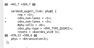
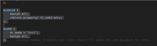
I can enabled USB3 function in kernel space and I it work. But same setting in uboot do not work. 

U-boot log:

U-Boot SPL 2024.04-gb40fba1b-dirty (May 05 2025 - 11:31:08 +0800)
SYSFW ABI: 4.0 (firmware rev 0x000a '10.0.8--v10.00.08 (Fiery Fox)')
Trying to boot from MMC2
Warning: Detected image signing certificate on GP device. Skipping certificate to prevent boot failure. This will fail if the image was also encrypted
Loading Environment from nowhere... OK
Starting ATF on ARM64 core...

NOTICE: BL31: v2.10.0(release):b40fba1b-dirty
NOTICE: BL31: Built : 15:53:26, May 7 2025
I/TC:
I/TC: Primary CPU initializing
I/TC: SYSFW ABI: 4.0 (firmware rev 0x000a '10.0.8--v10.00.08 (Fiery Fox)')
I/TC: HUK Initialized
I/TC: Activated SA2UL device
I/TC: Fixing SA2UL firewall owner for GP device
I/TC: Enabled firewalls for SA2UL TRNG device
I/TC: SA2UL TRNG initialized
I/TC: SA2UL Drivers initialized
I/TC: Primary CPU switching to normal world boot

U-Boot SPL 2024.04-gb40fba1b-dirty (May 07 2025 - 15:54:37 +0800)
SYSFW ABI: 4.0 (firmware rev 0x000a '10.0.8--v10.00.08 (Fiery Fox)')
Detected: J7X-BASE-CPB rev A
Detected: J7X-GESI-EXP rev E3
Trying to boot from MMC2
Warning: Detected image signing certificate on GP device. Skipping certificate to prevent boot failure. This will fail if the image was also encrypted


U-Boot 2024.04-gb40fba1b-dirty (May 07 2025 - 15:54:37 +0800)

SoC: J7200 SR1.0 GP
Model: Texas Instruments J7200 EVM
Board: J7200X-PM2-SOM rev E6
DRAM: 2 GiB (effective 4 GiB)
Core: 114 devices, 32 uclasses, devicetree: separate
Flash: 0 Bytes
MMC: mmc@4f80000: 0, mmc@4fb0000: 1
Loading Environment from SPIFlash... k3-navss-ringacc ringacc@2b800000: Ring Accelerator probed rings:286, gp-rings[96,32] sci-dev-id:235
k3-navss-ringacc ringacc@2b800000: dma-ring-reset-quirk: disabled
jedec_spi_nor flash@0: non-uniform erase sector maps are not supported yet.
SF: Detected s28hs512t with page size 256 Bytes, erase size 4 KiB, total 64 MiB
*** Warning - bad CRC, using default environment

In: serial@2800000
Out: serial@2800000
Err: serial@2800000
am65_cpsw_nuss ethernet@46000000: K3 CPSW: nuss_ver: 0x6BA02102 cpsw_ver: 0x6BA82102 ale_ver: 0x00293904 Ports:1
Detected: J7X-BASE-CPB rev A
Detected: J7X-GESI-EXP rev E3
Net: eth0: ethernet@46000000port@1
Hit any key to stop autoboot: 0
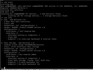
=> usb start
starting USB...
No working controllers found


  • Hi Alvin,

    Can you mention the changes you have made to try enabling the USB 3.0 in UBOOT ?

    Regards

    Gokul

  • // SPDX-License-Identifier: GPL-2.0
    /*
     * Copyright (C) 2020 Texas Instruments Incorporated - https://www.ti.com/
     */
    
    /dts-v1/;
    
    #include "k3-j7200-som-p0.dtsi"
    #include <dt-bindings/gpio/gpio.h>
    #include <dt-bindings/net/ti-dp83867.h>
    #include <dt-bindings/phy/phy.h>
    
    #include "k3-serdes.h"
    
    / {
    	compatible = "ti,j7200-evm", "ti,j7200";
    	model = "Texas Instruments J7200 EVM";
    
    	aliases {
    		serial0 = &wkup_uart0;
    		serial1 = &mcu_uart0;
    		serial2 = &main_uart0;
    		serial3 = &main_uart1;
    		serial5 = &main_uart3;
    		mmc0 = &main_sdhci0;
    		mmc1 = &main_sdhci1;
    	};
    
    	chosen {
    		stdout-path = "serial2:115200n8";
    	};
    
    	evm_12v0: fixedregulator-evm12v0 {
    		/* main supply */
    		compatible = "regulator-fixed";
    		regulator-name = "evm_12v0";
    		regulator-min-microvolt = <12000000>;
    		regulator-max-microvolt = <12000000>;
    		regulator-always-on;
    		regulator-boot-on;
    	};
    
    	vsys_3v3: fixedregulator-vsys3v3 {
    		/* Output of LM5140 */
    		compatible = "regulator-fixed";
    		regulator-name = "vsys_3v3";
    		regulator-min-microvolt = <3300000>;
    		regulator-max-microvolt = <3300000>;
    		vin-supply = <&evm_12v0>;
    		regulator-always-on;
    		regulator-boot-on;
    	};
    
    	vsys_5v0: fixedregulator-vsys5v0 {
    		/* Output of LM5140 */
    		compatible = "regulator-fixed";
    		regulator-name = "vsys_5v0";
    		regulator-min-microvolt = <5000000>;
    		regulator-max-microvolt = <5000000>;
    		vin-supply = <&evm_12v0>;
    		regulator-always-on;
    		regulator-boot-on;
    	};
    
    	vdd_mmc1: fixedregulator-sd {
    		/* Output of TPS22918 */
    		compatible = "regulator-fixed";
    		regulator-name = "vdd_mmc1";
    		regulator-min-microvolt = <3300000>;
    		regulator-max-microvolt = <3300000>;
    		regulator-boot-on;
    		enable-active-high;
    		vin-supply = <&vsys_3v3>;
    		gpio = <&exp2 2 GPIO_ACTIVE_HIGH>;
    	};
    
    	vdd_sd_dv: gpio-regulator-TLV71033 {
    		/* Output of TLV71033 */
    		compatible = "regulator-gpio";
    		regulator-name = "tlv71033";
    		pinctrl-names = "default";
    		pinctrl-0 = <&vdd_sd_dv_pins_default>;
    		regulator-min-microvolt = <1800000>;
    		regulator-max-microvolt = <3300000>;
    		regulator-boot-on;
    		vin-supply = <&vsys_5v0>;
    		gpios = <&main_gpio0 55 GPIO_ACTIVE_HIGH>;
    		states = <1800000 0x0>,
    			 <3300000 0x1>;
    	};
    
    	transceiver1: can-phy1 {
    		compatible = "ti,tcan1043";
    		#phy-cells = <0>;
    		max-bitrate = <5000000>;
    		pinctrl-names = "default";
    		pinctrl-0 = <&mcu_mcan0_gpio_pins_default>;
    		standby-gpios = <&wkup_gpio0 58 GPIO_ACTIVE_LOW>;
    		enable-gpios = <&wkup_gpio0 0 GPIO_ACTIVE_HIGH>;
    	};
    
    	transceiver2: can-phy2 {
    		compatible = "ti,tcan1042";
    		#phy-cells = <0>;
    		max-bitrate = <5000000>;
    		pinctrl-names = "default";
    		pinctrl-0 = <&mcu_mcan1_gpio_pins_default>;
    		standby-gpios = <&wkup_gpio0 2 GPIO_ACTIVE_HIGH>;
    	};
    
    	transceiver3: can-phy3 {
    		compatible = "ti,tcan1043";
    		#phy-cells = <0>;
    		max-bitrate = <5000000>;
    		standby-gpios = <&exp2 7 GPIO_ACTIVE_LOW>;
    		enable-gpios = <&exp2 6 GPIO_ACTIVE_HIGH>;
    		mux-states = <&mux0 1>;
    	};
    };
    
    &wkup_pmx2 {
    	mcu_uart0_pins_default: mcu-uart0-default-pins {
    		pinctrl-single,pins = <
    			J721E_WKUP_IOPAD(0x90, PIN_INPUT, 0) /* (E20) MCU_UART0_CTSn */
    			J721E_WKUP_IOPAD(0x94, PIN_OUTPUT, 0) /* (E21) MCU_UART0_RTSn */
    			J721E_WKUP_IOPAD(0x8c, PIN_INPUT, 0) /* (D20) MCU_UART0_RXD */
    			J721E_WKUP_IOPAD(0x88, PIN_OUTPUT, 0) /* (D19) MCU_UART0_TXD */
    		>;
    	};
    
    	wkup_uart0_pins_default: wkup-uart0-default-pins {
    		pinctrl-single,pins = <
    			J721E_WKUP_IOPAD(0x48, PIN_INPUT, 0) /* (B14) WKUP_UART0_RXD */
    			J721E_WKUP_IOPAD(0x4c, PIN_OUTPUT, 0) /* (A14) WKUP_UART0_TXD */
    		>;
    	};
    
    	mcu_cpsw_pins_default: mcu-cpsw-default-pins {
    		pinctrl-single,pins = <
    			J721E_WKUP_IOPAD(0x0000, PIN_OUTPUT, 0) /* MCU_RGMII1_TX_CTL */
    			J721E_WKUP_IOPAD(0x0004, PIN_INPUT, 0) /* MCU_RGMII1_RX_CTL */
    			J721E_WKUP_IOPAD(0x0008, PIN_OUTPUT, 0) /* MCU_RGMII1_TD3 */
    			J721E_WKUP_IOPAD(0x000c, PIN_OUTPUT, 0) /* MCU_RGMII1_TD2 */
    			J721E_WKUP_IOPAD(0x0010, PIN_OUTPUT, 0) /* MCU_RGMII1_TD1 */
    			J721E_WKUP_IOPAD(0x0014, PIN_OUTPUT, 0) /* MCU_RGMII1_TD0 */
    			J721E_WKUP_IOPAD(0x0020, PIN_INPUT, 0) /* MCU_RGMII1_RD3 */
    			J721E_WKUP_IOPAD(0x0024, PIN_INPUT, 0) /* MCU_RGMII1_RD2 */
    			J721E_WKUP_IOPAD(0x0028, PIN_INPUT, 0) /* MCU_RGMII1_RD1 */
    			J721E_WKUP_IOPAD(0x002c, PIN_INPUT, 0) /* MCU_RGMII1_RD0 */
    			J721E_WKUP_IOPAD(0x0018, PIN_OUTPUT, 0) /* MCU_RGMII1_TXC */
    			J721E_WKUP_IOPAD(0x001c, PIN_INPUT, 0) /* MCU_RGMII1_RXC */
    		>;
    	};
    
    	wkup_gpio_pins_default: wkup-gpio-default-pins {
    		pinctrl-single,pins = <
    			J721E_WKUP_IOPAD(0x70, PIN_INPUT, 7) /* (C14) WKUP_GPIO0_6 */
    		>;
    	};
    
    	mcu_mdio_pins_default: mcu-mdio1-default-pins {
    		pinctrl-single,pins = <
    			J721E_WKUP_IOPAD(0x0034, PIN_OUTPUT, 0) /* (L1) MCU_MDIO0_MDC */
    			J721E_WKUP_IOPAD(0x0030, PIN_INPUT, 0) /* (L4) MCU_MDIO0_MDIO */
    		>;
    	};
    
    	mcu_mcan0_pins_default: mcu-mcan0-default-pins {
    		pinctrl-single,pins = <
    			J721E_WKUP_IOPAD(0x54, PIN_INPUT, 0) /* (A17) MCU_MCAN0_RX */
    			J721E_WKUP_IOPAD(0x50, PIN_OUTPUT, 0) /* (A16) MCU_MCAN0_TX */
    		>;
    	};
    
    	mcu_mcan1_pins_default: mcu-mcan1-default-pins {
    		pinctrl-single,pins = <
    			J721E_WKUP_IOPAD(0x6c, PIN_INPUT, 0) /* (B16) WKUP_GPIO0_5.MCU_MCAN1_RX */
    			J721E_WKUP_IOPAD(0x68, PIN_OUTPUT, 0) /* (D13) WKUP_GPIO0_4.MCU_MCAN1_TX */
    		>;
    	};
    
    	mcu_mcan0_gpio_pins_default: mcu-mcan0-gpio-default-pins {
    		pinctrl-single,pins = <
    			J721E_WKUP_IOPAD(0x58, PIN_INPUT, 7) /* (B18) WKUP_GPIO0_0 */
    			J721E_WKUP_IOPAD(0x40, PIN_INPUT, 7) /* (B17) MCU_SPI0_D1 */
    		>;
    	};
    
    	mcu_mcan1_gpio_pins_default: mcu-mcan1-gpio-default-pins {
    		pinctrl-single,pins = <
    			J721E_WKUP_IOPAD(0x60, PIN_INPUT, 7) /* (D14) WKUP_GPIO0_2 */
    		>;
    	};
    };
    
    &main_pmx0 {
    	main_uart0_pins_default: main-uart0-default-pins {
    		pinctrl-single,pins = <
    			J721E_IOPAD(0xb0, PIN_INPUT, 0) /* (T16) UART0_RXD */
    			J721E_IOPAD(0xb4, PIN_OUTPUT, 0) /* (T17) UART0_TXD */
    			J721E_IOPAD(0xc0, PIN_INPUT, 2) /* (W3) SPI0_CS0.UART0_CTSn */
    			J721E_IOPAD(0xc4, PIN_OUTPUT, 2) /* (U5) SPI0_CS1.UART0_RTSn */
    		>;
    	};
    
    	main_uart1_pins_default: main-uart1-default-pins {
    		pinctrl-single,pins = <
    			J721E_IOPAD(0xb8, PIN_INPUT, 0) /* (T18) UART1_RXD */
    			J721E_IOPAD(0xbc, PIN_INPUT, 0) /* (T20) UART1_TXD */
    		>;
    	};
    
    	main_uart3_pins_default: main-uart3-default-pins {
    		pinctrl-single,pins = <
    			J721E_IOPAD(0x60, PIN_INPUT, 11) /* (T15) MCAN8_TX.UART3_CTSn */
    			J721E_IOPAD(0x30, PIN_INPUT, 11) /* (Y18) MCAN2_TX.UART3_RXD */
    		>;
    	};
    
    	main_i2c1_pins_default: main-i2c1-default-pins {
    		pinctrl-single,pins = <
    			J721E_IOPAD(0xdc, PIN_INPUT_PULLUP, 3) /* (U3) ECAP0_IN_APWM_OUT.I2C1_SCL */
    			J721E_IOPAD(0xe0, PIN_INPUT_PULLUP, 3) /* (T3) EXT_REFCLK1.I2C1_SDA */
    		>;
    	};
    
    	main_mmc1_pins_default: main-mmc1-default-pins {
    		pinctrl-single,pins = <
    			J721E_IOPAD(0x104, PIN_INPUT, 0) /* (M20) MMC1_CMD */
    			J721E_IOPAD(0x100, PIN_INPUT, 0) /* (P21) MMC1_CLK */
    			J721E_IOPAD(0xfc, PIN_INPUT, 0) /* (P25) MMC1_CLKLB */
    			J721E_IOPAD(0xf8, PIN_INPUT, 0) /* (M19) MMC1_DAT0 */
    			J721E_IOPAD(0xf4, PIN_INPUT, 0) /* (N21) MMC1_DAT1 */
    			J721E_IOPAD(0xf0, PIN_INPUT, 0) /* (N20) MMC1_DAT2 */
    			J721E_IOPAD(0xec, PIN_INPUT, 0) /* (N19) MMC1_DAT3 */
    			J721E_IOPAD(0xe4, PIN_INPUT, 8) /* (V1) TIMER_IO0.MMC1_SDCD */
    		>;
    	};
    
    	vdd_sd_dv_pins_default: vdd-sd-dv-default-pins {
    		pinctrl-single,pins = <
    			J721E_IOPAD(0xd0, PIN_OUTPUT, 7) /* (T5) SPI0_D1.GPIO0_55 */
    		>;
    	};
    
    	main_mcan3_pins_default: main-mcan3-default-pins {
    		pinctrl-single,pins = <
    			J721E_IOPAD(0x3c, PIN_INPUT, 0) /* (W16) MCAN3_RX */
    			J721E_IOPAD(0x38, PIN_OUTPUT, 0) /* (Y21) MCAN3_TX */
    		>;
    	};
    
    	mdio0_pins_default: mdio0-default-pins {
    		pinctrl-single,pins = <
    			J721E_IOPAD(0x00a8, PIN_OUTPUT, 5) /* (W19) UART8_TXD.MDIO0_MDC */
    			J721E_IOPAD(0x00a4, PIN_INPUT, 5) /* (W14) UART8_RXD.MDIO0_MDIO */
    		>;
    	};
    
    	rgmii1_default_pins: rgmii1-default-pins {
    		pinctrl-single,pins = <
    			J721E_IOPAD(0x4, PIN_INPUT, 4) /* (AC23) RGMII1_RD0 */
    			J721E_IOPAD(0x8, PIN_INPUT, 4) /* (AG22) RGMII1_RD1 */
    			J721E_IOPAD(0xc, PIN_INPUT, 4) /* (AF22) RGMII1_RD2 */
    			J721E_IOPAD(0x10, PIN_INPUT, 4) /* (AJ23) RGMII1_RD3 */
    			J721E_IOPAD(0x1c, PIN_INPUT, 4) /* (AD22) RGMII1_RXC */
    			J721E_IOPAD(0x14, PIN_INPUT, 4) /* (AH23) RGMII1_RX_CTL */
    			J721E_IOPAD(0x30, PIN_OUTPUT, 4) /* (AF24) RGMII1_TD0 */
    			J721E_IOPAD(0x34, PIN_OUTPUT, 4) /* (AJ24) RGMII1_TD1 */
    			J721E_IOPAD(0x38, PIN_OUTPUT, 4) /* (AG24) RGMII1_TD2 */
    			J721E_IOPAD(0x3c, PIN_OUTPUT, 4) /* (AD24) RGMII1_TD3 */
    			J721E_IOPAD(0x44, PIN_OUTPUT, 4) /* (AE24) RGMII1_TXC */
    			J721E_IOPAD(0x40, PIN_OUTPUT, 4) /* (AC24) RGMII1_TX_CTL */
    		>;
    	};
    
    	rgmii2_default_pins: rgmii2-default-pins {
    		pinctrl-single,pins = <
    			J721E_IOPAD(0x7C, PIN_INPUT, 4) /* (AE22) RGMII2_RD0 */
    			J721E_IOPAD(0x80, PIN_INPUT, 4) /* (AG23) RGMII2_RD1 */
    			J721E_IOPAD(0x84, PIN_INPUT, 4) /* (AF23) RGMII2_RD2 */
    			J721E_IOPAD(0x88, PIN_INPUT, 4) /* (AD23) RGMII2_RD3 */
    			J721E_IOPAD(0x78, PIN_INPUT, 4) /* (AE23) RGMII2_RXC */
    			J721E_IOPAD(0x8C, PIN_INPUT, 4) /* (AH24) RGMII2_RX_CTL */
    			J721E_IOPAD(0x90, PIN_OUTPUT, 4) /* (AJ25) RGMII2_TD0 */
    			J721E_IOPAD(0x94, PIN_OUTPUT, 4) /* (AH25) RGMII2_TD1 */
    			J721E_IOPAD(0x98, PIN_OUTPUT, 4) /* (AG25) RGMII2_TD2 */
    			J721E_IOPAD(0x9C, PIN_OUTPUT, 4) /* (AH26) RGMII2_TD3 */
    			J721E_IOPAD(0x28, PIN_OUTPUT, 4) /* (AJ26) RGMII2_TXC */
    			J721E_IOPAD(0xA0, PIN_OUTPUT, 4) /* (AJ27) RGMII2_TX_CTL */
    		>;
    	};
    
    	rgmii3_default_pins: rgmii3-default-pins {
    		pinctrl-single,pins = <
    			J721E_IOPAD(0x4C, PIN_INPUT, 4) /* (AF28) RGMII3_RD0 */
    			J721E_IOPAD(0x50, PIN_INPUT, 4) /* (AE28) RGMII3_RD1 */
    			J721E_IOPAD(0x54, PIN_INPUT, 4) /* (AE27) RGMII3_RD2 */
    			J721E_IOPAD(0x58, PIN_INPUT, 4) /* (AD26) RGMII3_RD3 */
    			J721E_IOPAD(0x48, PIN_INPUT, 4) /* (AE26) RGMII3_RXC */
    			J721E_IOPAD(0x5C, PIN_INPUT, 4) /* (AD25) RGMII3_RX_CTL */
    			J721E_IOPAD(0x60, PIN_OUTPUT, 4) /* (AJ28) RGMII3_TD0 */
    			J721E_IOPAD(0x64, PIN_OUTPUT, 4) /* (AH27) RGMII3_TD1 */
    			J721E_IOPAD(0x68, PIN_OUTPUT, 4) /* (AH29) RGMII3_TD2 */
    			J721E_IOPAD(0x6C, PIN_OUTPUT, 4) /* (AG28) RGMII3_TD3 */
    			J721E_IOPAD(0x74, PIN_OUTPUT, 4) /* (AH28) RGMII3_TXC */
    			J721E_IOPAD(0x70, PIN_OUTPUT, 4) /* (AG27) RGMII3_TX_CTL */
    		>;
    	};
    
    	rgmii4_1_default_pins: rgmii4_1-default-pins {
    		pinctrl-single,pins = <
    			J721E_IOPAD(0x20, PIN_INPUT, 4) /* (AE29) RGMII4_RD0 */
    			J721E_IOPAD(0x24, PIN_INPUT, 4) /* (AD28) RGMII4_RD1 */
    			J721E_IOPAD(0x2C, PIN_INPUT, 4) /* (AD27) RGMII4_RD2 */
    			J721E_IOPAD(0xAC, PIN_INPUT, 4) /* (AC25) RGMII4_RD3 */
    			J721E_IOPAD(0x18, PIN_INPUT, 4) /* (AC26) RGMII4_RXC */
    			J721E_IOPAD(0xB4, PIN_OUTPUT, 4) /* (AF26) RGMII4_TD2 */
    			J721E_IOPAD(0xB8, PIN_OUTPUT, 4) /* (AE25) RGMII4_TD3 */
    			J721E_IOPAD(0xB0, PIN_OUTPUT, 4) /* (AG29) RGMII4_TXC */
    			J721E_IOPAD(0xBC, PIN_OUTPUT, 4) /* (AF29) RGMII4_TX_CTL */
    		>;
    	};
    };
    
    &main_pmx2 {
    	rgmii4_2_default_pins: rgmii4_2-default-pins {
    		pinctrl-single,pins = <
    			J721E_IOPAD(0x8, PIN_OUTPUT, 4) /* (AF27) RGMII4_TD1 */
    		>;
    	};
    
    	main_usbss0_pins_default: main-usbss0-default-pins {
    		pinctrl-single,pins = <
    			J721E_IOPAD(0x04, PIN_OUTPUT, 0) /* (T4) USB0_DRVVBUS */
    		>;
    	};
    };
    
    &main_pmx3 {
    	rgmii4_3_default_pins: rgmii4_3-default-pins {
    		pinctrl-single,pins = <
    			J721E_IOPAD(0x0, PIN_INPUT, 4) /* (AD29) RGMII4_RX_CTL */
    			J721E_IOPAD(0x4, PIN_OUTPUT, 4) /* (AG26) RGMII4_TD0 */
    			
    		>;
    	};
    };
    
    &wkup_uart0 {
    	/* Wakeup UART is used by System firmware */
    	status = "reserved";
    	pinctrl-names = "default";
    	pinctrl-0 = <&wkup_uart0_pins_default>;
    };
    
    &mcu_uart0 {
    	status = "okay";
    	pinctrl-names = "default";
    	pinctrl-0 = <&mcu_uart0_pins_default>;
    };
    
    &main_uart0 {
    	status = "okay";
    	/* Shared with ATF on this platform */
    	power-domains = <&k3_pds 146 TI_SCI_PD_SHARED>;
    	pinctrl-names = "default";
    	pinctrl-0 = <&main_uart0_pins_default>;
    };
    
    &main_uart1 {
    	status = "okay";
    	/* Default pinmux */
    	pinctrl-names = "default";
    	pinctrl-0 = <&main_uart1_pins_default>;
    };
    
    &main_uart2 {
    	/* MAIN UART 2 is used by R5F firmware */
    	status = "reserved";
    };
    
    &main_uart3 {
    	/* Shared with MCAN Interface */
    	status = "okay";
    	pinctrl-names = "default";
    	pinctrl-0 = <&main_uart3_pins_default>;
    };
    
    &main_gpio0 {
    	status = "okay";
    };
    
    &wkup_gpio0 {
    	status = "okay";
    	pinctrl-names = "default";
    	pinctrl-0 = <&wkup_gpio_pins_default>;
    };
    
    &mcu_cpsw {
    	pinctrl-names = "default";
    	pinctrl-0 = <&mcu_cpsw_pins_default>, <&mcu_mdio_pins_default>;
    
    	cpts@3d000 {
    		/* Map HW4_TS_PUSH to GENF1 */
    		ti,pps = <3 1>;
    	};
    };
    
    &davinci_mdio {
    	phy0: ethernet-phy@0 {
    		reg = <0>;
    		ti,rx-internal-delay = <DP83867_RGMIIDCTL_2_00_NS>;
    		ti,tx-internal-delay = <DP83867_RGMIIDCTL_2_00_NS>;
    		ti,fifo-depth = <DP83867_PHYCR_FIFO_DEPTH_4_B_NIB>;
    	};
    };
    
    &cpsw_port1 {
    	phy-mode = "rgmii-rxid";
    	phy-handle = <&phy0>;
    };
    
    &cpsw5g_mdio {
    	status = "okay";
    	pinctrl-names = "default";
    	pinctrl-0 = <&mdio0_pins_default>;
    	reset-gpios = <&exp2 17 GPIO_ACTIVE_LOW>;
    	reset-post-delay-us = <120000>;
    	#address-cells = <1>;
    	#size-cells = <0>;
    
    	cpsw5g_phy0: ethernet-phy@0 {
    		reg = <0>;
    		ti,rx-internal-delay = <DP83867_RGMIIDCTL_2_00_NS>;
    		ti,rx-internal-delay = <DP83867_RGMIIDCTL_2_00_NS>;
    		ti,fifo-depth = <DP83867_PHYCR_FIFO_DEPTH_4_B_NIB>;
    
    	};
    	cpsw5g_phy1: ethernet-phy@17 {
    		reg = <17>;
    	};
    	cpsw5g_phy2: ethernet-phy@18 {
    		reg = <18>;
    	};
    	cpsw5g_phy3: ethernet-phy@19 {
    		reg = <19>;
    	};
    };
    
    &cpsw0 {
    	status = "okay";
    	pinctrl-names = "default";
    	pinctrl-0 = <&rgmii2_default_pins>;
    };
    
    &cpsw0_port1 {
    	status = "disabled";
    	phy-handle = <&cpsw5g_phy1>;
    	phy-mode = "rgmii-rxid";
    	mac-address = [00 00 00 00 00 00];
    	phys = <&cpsw0_phy_gmii_sel 1>;
    };
    
    &cpsw0_port2 {
    	status = "okay";
    	phy-handle = <&cpsw5g_phy0>;
    	phy-mode = "rgmii-rxid";
    	mac-address = [00 00 00 00 00 00];
    	phys = <&cpsw0_phy_gmii_sel 2>;
    };
    
    &cpsw0_port3 {
    	status = "disabled";
    	phy-handle = <&cpsw5g_phy2>;
    	phy-mode = "rgmii-rxid";
    	mac-address = [00 00 00 00 00 00];
    	phys = <&cpsw0_phy_gmii_sel 3>;
    };
    
    &cpsw0_port4 {
    	status = "disabled";
    	phy-handle = <&cpsw5g_phy3>;
    	phy-mode = "rgmii-rxid";
    	mac-address = [00 00 00 00 00 00];
    	phys = <&cpsw0_phy_gmii_sel 4>;
    };
    
    &main_i2c0 {
    	status = "okay";
    	pinctrl-names = "default";
    	pinctrl-0 = <&main_i2c0_pins_default>;
    	clock-frequency = <400000>;
    
    	exp1: gpio@20 {
    		compatible = "ti,tca6416";
    		reg = <0x20>;
    		gpio-controller;
    		#gpio-cells = <2>;
    	};
    
    	exp2: gpio@22 {
    		compatible = "ti,tca6424";
    		reg = <0x22>;
    		gpio-controller;
    		#gpio-cells = <2>;
    	};
    };
    
    &exp1 {
    	p15-hog {
    		/* P15 - EXP_MUX2 */
    		gpio-hog;
    		gpios = <13 GPIO_ACTIVE_HIGH>;
    		output-high;
    		line-name = "EXP_MUX2";
    	};
    
    	p16-hog {
    		/* P16 - EXP_MUX3 */
    		gpio-hog;
    		gpios = <14 GPIO_ACTIVE_HIGH>;
    		output-high;
    		line-name = "EXP_MUX3";
    	};
    };
    
    /*
     * The j7200 CPB board is identical to the CPB used for J721E, the SOMs can be
     * swapped on the CPB.
     *
     * main_i2c1 of J7200 is connected to the CPB i2c bus labeled as i2c3.
     * The i2c1 of the CPB (as it is labeled) is not connected to j7200.
     */
    &main_i2c1 {
    	status = "okay";
    	pinctrl-names = "default";
    	pinctrl-0 = <&main_i2c1_pins_default>;
    	clock-frequency = <400000>;
    
    	exp3: gpio@20 {
    		compatible = "ti,tca6408";
    		reg = <0x20>;
    		gpio-controller;
    		#gpio-cells = <2>;
    		gpio-line-names = "CODEC_RSTz", "CODEC_SPARE1", "UB926_RESETn",
    				  "UB926_LOCK", "UB926_PWR_SW_CNTRL",
    				  "UB926_TUNER_RESET", "UB926_GPIO_SPARE", "";
    	};
    };
    
    &main_sdhci0 {
    	/* eMMC */
    	status = "okay";
    	non-removable;
    	ti,driver-strength-ohm = <50>;
    	disable-wp;
    };
    
    &main_sdhci1 {
    	/* SD card */
    	status = "okay";
    	pinctrl-0 = <&main_mmc1_pins_default>;
    	pinctrl-names = "default";
    	vmmc-supply = <&vdd_mmc1>;
    	vqmmc-supply = <&vdd_sd_dv>;
    	ti,driver-strength-ohm = <50>;
    	disable-wp;
    };
    
    &usb_serdes_mux {
    	idle-states = <1>; /* USB0 to SERDES setting  0:lane 1 , 1:lane 3 */
    };
    
    &serdes_ln_ctrl {
    	idle-states = <J7200_SERDES0_LANE0_PCIE1_LANE0>, <J7200_SERDES0_LANE1_PCIE1_LANE1>,
    	<J7200_SERDES0_LANE2_IP3_UNUSED>, <J7200_SERDES0_LANE3_USB>;
    };
    
    &usbss0 {
    	pinctrl-names = "default";
    	pinctrl-0 = <&main_usbss0_pins_default>;
    	ti,vbus-divider;
    	/* ti,usb2-only; */
    };
    
    &tscadc0 {
    	adc {
    		ti,adc-channels = <0 1 2 3 4 5 6 7>;
    	};
    };
    
    &serdes_refclk {
    	clock-frequency = <100000000>;
    };
    
    &serdes0 {
    	serdes0_pcie_link: phy@0 {
    		reg = <0>;
    		cdns,num-lanes = <2>;
    		#phy-cells = <0>;
    		cdns,phy-type = <PHY_TYPE_PCIE>;
    		resets = <&serdes_wiz0 1>, <&serdes_wiz0 2>;
    	};
    /*
    	serdes0_qsgmii_link: phy@1 {
    		reg = <1>;
    		cdns,num-lanes = <1>;
    		#phy-cells = <0>;
    		cdns,phy-type = <PHY_TYPE_QSGMII>;
    		resets = <&serdes_wiz0 3>;
    	};
    */
    	serdes0_usb_link: phy@2 {
    		reg = <3>;
    		cdns,num-lanes = <1>;
    		#phy-cells = <0>;
    		cdns,phy-type = <PHY_TYPE_USB3>;
    		resets = <&serdes_wiz0 4>;
    	};
    };
    
    /*
    &serdes0_qsgmii_link {
    	status = "disabled";
    };
    */
    
    &usb0 {
    	dr_mode = "host";
    	maximum-speed = "super-speed";
    	phys = <&serdes0_usb_link>;
    	phy-names = "cdns3,usb3-phy";
    };
    
    &pcie1_rc {
    	status = "okay";
    	reset-gpios = <&exp1 2 GPIO_ACTIVE_HIGH>;
    	phys = <&serdes0_pcie_link>;
    	phy-names = "pcie-phy";
    	num-lanes = <2>;
    	max-link-speed = <1>;
    };
    
    &mcu_mcan0 {
    	status = "okay";
    	pinctrl-names = "default";
    	pinctrl-0 = <&mcu_mcan0_pins_default>;
    	phys = <&transceiver1>;
    };
    
    &mcu_mcan1 {
    	status = "okay";
    	pinctrl-names = "default";
    	pinctrl-0 = <&mcu_mcan1_pins_default>;
    	phys = <&transceiver2>;
    };
    
    &main_mcan3 {
    	status = "okay";
    	pinctrl-names = "default";
    	pinctrl-0 = <&main_mcan3_pins_default>;
    	phys = <&transceiver3>;
    };
    
    #define K3_TS_OFFSET(pa, val)  (0x4+(pa)*4) (0x10000 | val)
    
    &timesync_router {
    	status = "okay";
    	pinctrl-names = "default";
    	pinctrl-0 = <&mcu_cpsw_cpts>;
    
    	/* Use Time Sync Router to map GENF1 input to HW4_TS_PUSH output */
    	mcu_cpsw_cpts: mcu-cpsw-cpts {
    		pinctrl-single,pins = <
    			/* pps [mcu cpsw cpts genf1] in17 -> out25 [mcu cpsw cpts hw4_push] */
    			K3_TS_OFFSET(25, 17)
    			>;
    	};
    };
    // SPDX-License-Identifier: GPL-2.0
    /*
     * Device Tree Source for J7200 SoC Family Main Domain peripherals
     *
     * Copyright (C) 2020-2021 Texas Instruments Incorporated - https://www.ti.com/
     */
    
    / {
    	serdes_refclk: serdes-refclk {
    		#clock-cells = <0>;
    		compatible = "fixed-clock";
    	};
    };
    
    &cbass_main {
    	msmc_ram: sram@70000000 {
    		compatible = "mmio-sram";
    		reg = <0x00 0x70000000 0x00 0x100000>;
    		#address-cells = <1>;
    		#size-cells = <1>;
    		ranges = <0x00 0x00 0x70000000 0x100000>;
    
    		atf-sram@0 {
    			reg = <0x00 0x20000>;
    		};
    	};
    
    	scm_conf: scm-conf@100000 {
    		compatible = "ti,j721e-system-controller", "syscon", "simple-mfd";
    		reg = <0x00 0x00100000 0x00 0x1c000>;
    		#address-cells = <1>;
    		#size-cells = <1>;
    		ranges = <0x00 0x00 0x00100000 0x1c000>;
    
    		serdes_ln_ctrl: mux-controller@4080 {
    			compatible = "reg-mux";
    			reg = <0x4080 0x20>;
    			#mux-control-cells = <1>;
    			mux-reg-masks = <0x0 0x3>, <0x4 0x3>, /* SERDES0 lane0/1 select */
    					<0x8 0x3>, <0xc 0x3>; /* SERDES0 lane2/3 select */
    		};
    
    		cpsw0_phy_gmii_sel: phy@4044 {
    			compatible = "ti,j7200-cpsw5g-phy-gmii-sel";
    			ti,qsgmii-main-ports = <1>;
    			reg = <0x4044 0x10>;
    			#phy-cells = <1>;
    		};
    
    		usb_serdes_mux: mux-controller@4000 {
    			compatible = "reg-mux";
    			reg = <0x4000 0x4>;
    			#mux-control-cells = <1>;
    			mux-reg-masks = <0x0 0x8000000>; /* USB0 to SERDES0 lane 1/3 mux */
    		};
    	};
    
    	gic500: interrupt-controller@1800000 {
    		compatible = "arm,gic-v3";
    		#address-cells = <2>;
    		#size-cells = <2>;
    		ranges;
    		#interrupt-cells = <3>;
    		interrupt-controller;
    		reg = <0x00 0x01800000 0x00 0x10000>,	/* GICD */
    		      <0x00 0x01900000 0x00 0x100000>,	/* GICR */
    		      <0x00 0x6f000000 0x00 0x2000>,	/* GICC */
    		      <0x00 0x6f010000 0x00 0x1000>,	/* GICH */
    		      <0x00 0x6f020000 0x00 0x2000>;	/* GICV */
    
    		/* vcpumntirq: virtual CPU interface maintenance interrupt */
    		interrupts = <GIC_PPI 9 IRQ_TYPE_LEVEL_HIGH>;
    
    		gic_its: msi-controller@1820000 {
    			compatible = "arm,gic-v3-its";
    			reg = <0x00 0x01820000 0x00 0x10000>;
    			socionext,synquacer-pre-its = <0x1000000 0x400000>;
    			msi-controller;
    			#msi-cells = <1>;
    		};
    	};
    
    	main_gpio_intr: interrupt-controller@a00000 {
    		compatible = "ti,sci-intr";
    		reg = <0x00 0x00a00000 0x00 0x800>;
    		ti,intr-trigger-type = <1>;
    		interrupt-controller;
    		interrupt-parent = <&gic500>;
    		#interrupt-cells = <1>;
    		ti,sci = <&dmsc>;
    		ti,sci-dev-id = <131>;
    		ti,interrupt-ranges = <8 392 56>;
    	};
    
    	main_navss: bus@30000000 {
    		compatible = "simple-bus";
    		#address-cells = <2>;
    		#size-cells = <2>;
    		ranges = <0x00 0x30000000 0x00 0x30000000 0x00 0x0c400000>;
    		ti,sci-dev-id = <199>;
    		dma-coherent;
    		dma-ranges;
    
    		main_navss_intr: interrupt-controller@310e0000 {
    			compatible = "ti,sci-intr";
    			reg = <0x00 0x310e0000 0x00 0x4000>;
    			ti,intr-trigger-type = <4>;
    			interrupt-controller;
    			interrupt-parent = <&gic500>;
    			#interrupt-cells = <1>;
    			ti,sci = <&dmsc>;
    			ti,sci-dev-id = <213>;
    			ti,interrupt-ranges = <0 64 64>,
    					      <64 448 64>,
    					      <128 672 64>;
    		};
    
    		main_udmass_inta: msi-controller@33d00000 {
    			compatible = "ti,sci-inta";
    			reg = <0x00 0x33d00000 0x00 0x100000>;
    			interrupt-controller;
    			#interrupt-cells = <0>;
    			interrupt-parent = <&main_navss_intr>;
    			msi-controller;
    			ti,sci = <&dmsc>;
    			ti,sci-dev-id = <209>;
    			ti,interrupt-ranges = <0 0 256>;
    		};
    
    		secure_proxy_main: mailbox@32c00000 {
    			compatible = "ti,am654-secure-proxy";
    			#mbox-cells = <1>;
    			reg-names = "target_data", "rt", "scfg";
    			reg = <0x00 0x32c00000 0x00 0x100000>,
    			      <0x00 0x32400000 0x00 0x100000>,
    			      <0x00 0x32800000 0x00 0x100000>;
    			interrupt-names = "rx_011";
    			interrupts = <GIC_SPI 37 IRQ_TYPE_LEVEL_HIGH>;
    		};
    
    		hwspinlock: spinlock@30e00000 {
    			compatible = "ti,am654-hwspinlock";
    			reg = <0x00 0x30e00000 0x00 0x1000>;
    			#hwlock-cells = <1>;
    		};
    
    		mailbox0_cluster0: mailbox@31f80000 {
    			compatible = "ti,am654-mailbox";
    			reg = <0x00 0x31f80000 0x00 0x200>;
    			#mbox-cells = <1>;
    			ti,mbox-num-users = <4>;
    			ti,mbox-num-fifos = <16>;
    			interrupt-parent = <&main_navss_intr>;
    			status = "disabled";
    		};
    
    		mailbox0_cluster1: mailbox@31f81000 {
    			compatible = "ti,am654-mailbox";
    			reg = <0x00 0x31f81000 0x00 0x200>;
    			#mbox-cells = <1>;
    			ti,mbox-num-users = <4>;
    			ti,mbox-num-fifos = <16>;
    			interrupt-parent = <&main_navss_intr>;
    			status = "disabled";
    		};
    
    		mailbox0_cluster2: mailbox@31f82000 {
    			compatible = "ti,am654-mailbox";
    			reg = <0x00 0x31f82000 0x00 0x200>;
    			#mbox-cells = <1>;
    			ti,mbox-num-users = <4>;
    			ti,mbox-num-fifos = <16>;
    			interrupt-parent = <&main_navss_intr>;
    			status = "disabled";
    		};
    
    		mailbox0_cluster3: mailbox@31f83000 {
    			compatible = "ti,am654-mailbox";
    			reg = <0x00 0x31f83000 0x00 0x200>;
    			#mbox-cells = <1>;
    			ti,mbox-num-users = <4>;
    			ti,mbox-num-fifos = <16>;
    			interrupt-parent = <&main_navss_intr>;
    			status = "disabled";
    		};
    
    		mailbox0_cluster4: mailbox@31f84000 {
    			compatible = "ti,am654-mailbox";
    			reg = <0x00 0x31f84000 0x00 0x200>;
    			#mbox-cells = <1>;
    			ti,mbox-num-users = <4>;
    			ti,mbox-num-fifos = <16>;
    			interrupt-parent = <&main_navss_intr>;
    			status = "disabled";
    		};
    
    		mailbox0_cluster5: mailbox@31f85000 {
    			compatible = "ti,am654-mailbox";
    			reg = <0x00 0x31f85000 0x00 0x200>;
    			#mbox-cells = <1>;
    			ti,mbox-num-users = <4>;
    			ti,mbox-num-fifos = <16>;
    			interrupt-parent = <&main_navss_intr>;
    			status = "disabled";
    		};
    
    		mailbox0_cluster6: mailbox@31f86000 {
    			compatible = "ti,am654-mailbox";
    			reg = <0x00 0x31f86000 0x00 0x200>;
    			#mbox-cells = <1>;
    			ti,mbox-num-users = <4>;
    			ti,mbox-num-fifos = <16>;
    			interrupt-parent = <&main_navss_intr>;
    			status = "disabled";
    		};
    
    		mailbox0_cluster7: mailbox@31f87000 {
    			compatible = "ti,am654-mailbox";
    			reg = <0x00 0x31f87000 0x00 0x200>;
    			#mbox-cells = <1>;
    			ti,mbox-num-users = <4>;
    			ti,mbox-num-fifos = <16>;
    			interrupt-parent = <&main_navss_intr>;
    			status = "disabled";
    		};
    
    		mailbox0_cluster8: mailbox@31f88000 {
    			compatible = "ti,am654-mailbox";
    			reg = <0x00 0x31f88000 0x00 0x200>;
    			#mbox-cells = <1>;
    			ti,mbox-num-users = <4>;
    			ti,mbox-num-fifos = <16>;
    			interrupt-parent = <&main_navss_intr>;
    			status = "disabled";
    		};
    
    		mailbox0_cluster9: mailbox@31f89000 {
    			compatible = "ti,am654-mailbox";
    			reg = <0x00 0x31f89000 0x00 0x200>;
    			#mbox-cells = <1>;
    			ti,mbox-num-users = <4>;
    			ti,mbox-num-fifos = <16>;
    			interrupt-parent = <&main_navss_intr>;
    			status = "disabled";
    		};
    
    		mailbox0_cluster10: mailbox@31f8a000 {
    			compatible = "ti,am654-mailbox";
    			reg = <0x00 0x31f8a000 0x00 0x200>;
    			#mbox-cells = <1>;
    			ti,mbox-num-users = <4>;
    			ti,mbox-num-fifos = <16>;
    			interrupt-parent = <&main_navss_intr>;
    			status = "disabled";
    		};
    
    		mailbox0_cluster11: mailbox@31f8b000 {
    			compatible = "ti,am654-mailbox";
    			reg = <0x00 0x31f8b000 0x00 0x200>;
    			#mbox-cells = <1>;
    			ti,mbox-num-users = <4>;
    			ti,mbox-num-fifos = <16>;
    			interrupt-parent = <&main_navss_intr>;
    			status = "disabled";
    		};
    
    		main_ringacc: ringacc@3c000000 {
    			compatible = "ti,am654-navss-ringacc";
    			reg = <0x00 0x3c000000 0x00 0x400000>,
    			      <0x00 0x38000000 0x00 0x400000>,
    			      <0x00 0x31120000 0x00 0x100>,
    			      <0x00 0x33000000 0x00 0x40000>,
    			      <0x00 0x31080000 0x00 0x40000>;
    			reg-names = "rt", "fifos", "proxy_gcfg", "proxy_target", "cfg";
    			ti,num-rings = <1024>;
    			ti,sci-rm-range-gp-rings = <0x1>; /* GP ring range */
    			ti,sci = <&dmsc>;
    			ti,sci-dev-id = <211>;
    			msi-parent = <&main_udmass_inta>;
    		};
    
    		main_udmap: dma-controller@31150000 {
    			compatible = "ti,j721e-navss-main-udmap";
    			reg = <0x00 0x31150000 0x00 0x100>,
    			      <0x00 0x34000000 0x00 0x100000>,
    			      <0x00 0x35000000 0x00 0x100000>,
    			      <0x00 0x30b00000 0x00 0x4000>,
    			      <0x00 0x30c00000 0x00 0x4000>,
    			      <0x00 0x30d00000 0x00 0x4000>;
    			reg-names = "gcfg", "rchanrt", "tchanrt",
    				    "tchan", "rchan", "rflow";
    			msi-parent = <&main_udmass_inta>;
    			#dma-cells = <1>;
    
    			ti,sci = <&dmsc>;
    			ti,sci-dev-id = <212>;
    			ti,ringacc = <&main_ringacc>;
    
    			ti,sci-rm-range-tchan = <0x0d>, /* TX_CHAN */
    						<0x0f>, /* TX_HCHAN */
    						<0x10>; /* TX_UHCHAN */
    			ti,sci-rm-range-rchan = <0x0a>, /* RX_CHAN */
    						<0x0b>, /* RX_HCHAN */
    						<0x0c>; /* RX_UHCHAN */
    			ti,sci-rm-range-rflow = <0x00>; /* GP RFLOW */
    		};
    
    		cpts@310d0000 {
    			compatible = "ti,j721e-cpts";
    			reg = <0x00 0x310d0000 0x00 0x400>;
    			reg-names = "cpts";
    			clocks = <&k3_clks 201 1>;
    			clock-names = "cpts";
    			interrupts-extended = <&main_navss_intr 391>;
    			interrupt-names = "cpts";
    			ti,cpts-periodic-outputs = <6>;
    			ti,cpts-ext-ts-inputs = <8>;
    		};
    	};
    
    	cpsw0: ethernet@c000000 {
    		compatible = "ti,j7200-cpswxg-nuss";
    		#address-cells = <2>;
    		#size-cells = <2>;
    		reg = <0x00 0xc000000 0x00 0x200000>;
    		reg-names = "cpsw_nuss";
    		ranges = <0x00 0x00 0x00 0xc000000 0x00 0x200000>;
    		clocks = <&k3_clks 19 33>;
    		clock-names = "fck";
    		power-domains = <&k3_pds 19 TI_SCI_PD_EXCLUSIVE>;
    
    		dmas = <&main_udmap 0xca00>,
    		       <&main_udmap 0xca01>,
    		       <&main_udmap 0xca02>,
    		       <&main_udmap 0xca03>,
    		       <&main_udmap 0xca04>,
    		       <&main_udmap 0xca05>,
    		       <&main_udmap 0xca06>,
    		       <&main_udmap 0xca07>,
    		       <&main_udmap 0x4a00>;
    		dma-names = "tx0", "tx1", "tx2", "tx3",
    			    "tx4", "tx5", "tx6", "tx7",
    			    "rx";
    
    		status = "disabled";
    
    		ethernet-ports {
    			#address-cells = <1>;
    			#size-cells = <0>;
    			cpsw0_port1: port@1 {
    				reg = <1>;
    				ti,mac-only;
    				label = "port1";
    				status = "disabled";
    			};
    
    			cpsw0_port2: port@2 {
    				reg = <2>;
    				ti,mac-only;
    				label = "port2";
    				status = "disabled";
    			};
    
    			cpsw0_port3: port@3 {
    				reg = <3>;
    				ti,mac-only;
    				label = "port3";
    				status = "disabled";
    			};
    
    			cpsw0_port4: port@4 {
    				reg = <4>;
    				ti,mac-only;
    				label = "port4";
    				status = "disabled";
    			};
    		};
    
    		cpsw5g_mdio: mdio@f00 {
    			compatible = "ti,cpsw-mdio","ti,davinci_mdio";
    			reg = <0x00 0xf00 0x00 0x100>;
    			#address-cells = <1>;
    			#size-cells = <0>;
    			clocks = <&k3_clks 19 33>;
    			clock-names = "fck";
    			bus_freq = <1000000>;
    			status = "disabled";
    		};
    
    		cpts@3d000 {
    			compatible = "ti,j721e-cpts";
    			reg = <0x00 0x3d000 0x00 0x400>;
    			clocks = <&k3_clks 19 16>;
    			clock-names = "cpts";
    			interrupts-extended = <&gic500 GIC_SPI 16 IRQ_TYPE_LEVEL_HIGH>;
    			interrupt-names = "cpts";
    			ti,cpts-ext-ts-inputs = <4>;
    			ti,cpts-periodic-outputs = <2>;
    		};
    	};
    
    	/* TIMERIO pad input CTRLMMR_TIMER*_CTRL registers */
    	main_timerio_input: pinctrl@104200 {
    		compatible = "ti,j7200-padconf", "pinctrl-single";
    		reg = <0x0 0x104200 0x0 0x50>;
    		#pinctrl-cells = <1>;
    		pinctrl-single,register-width = <32>;
    		pinctrl-single,function-mask = <0x000001ff>;
    	};
    
    	/* TIMERIO pad output CTCTRLMMR_TIMERIO*_CTRL registers */
    	main_timerio_output: pinctrl@104280 {
    		compatible = "ti,j7200-padconf", "pinctrl-single";
    		reg = <0x0 0x104280 0x0 0x20>;
    		#pinctrl-cells = <1>;
    		pinctrl-single,register-width = <32>;
    		pinctrl-single,function-mask = <0x0000001f>;
    	};
    
    	main_pmx0: pinctrl@11c000 {
    		compatible = "ti,j7200-padconf", "pinctrl-single";
    		/* Proxy 0 addressing */
    		reg = <0x00 0x11c000 0x00 0x10c>;
    		#pinctrl-cells = <1>;
    		pinctrl-single,register-width = <32>;
    		pinctrl-single,function-mask = <0xffffffff>;
    	};
    
    	main_pmx1: pinctrl@11c110 {
    		compatible = "ti,j7200-padconf", "pinctrl-single";
    		/* Proxy 0 addressing */
    		reg = <0x00 0x11c110 0x00 0x004>;
    		#pinctrl-cells = <1>;
    		pinctrl-single,register-width = <32>;
    		pinctrl-single,function-mask = <0xffffffff>;
    	};
    
    	main_pmx2: pinctrl@11c11c {
    		compatible = "ti,j7200-padconf", "pinctrl-single";
    		/* Proxy 0 addressing */
    		reg = <0x00 0x11c11c 0x00 0x00c>;
    		#pinctrl-cells = <1>;
    		pinctrl-single,register-width = <32>;
    		pinctrl-single,function-mask = <0xffffffff>;
    	};
    
    	main_pmx3: pinctrl@11c164 {
    		compatible = "ti,j7200-padconf", "pinctrl-single";
    		/* Proxy 0 addressing */
    		reg = <0x00 0x11c164 0x00 0x008>;
    		#pinctrl-cells = <1>;
    		pinctrl-single,register-width = <32>;
    		pinctrl-single,function-mask = <0xffffffff>;
    	};
    
    	main_uart0: serial@2800000 {
    		compatible = "ti,j721e-uart", "ti,am654-uart";
    		reg = <0x00 0x02800000 0x00 0x100>;
    		interrupts = <GIC_SPI 192 IRQ_TYPE_LEVEL_HIGH>;
    		clock-frequency = <48000000>;
    		current-speed = <115200>;
    		power-domains = <&k3_pds 146 TI_SCI_PD_EXCLUSIVE>;
    		clocks = <&k3_clks 146 2>;
    		clock-names = "fclk";
    		status = "disabled";
    	};
    
    	main_uart1: serial@2810000 {
    		compatible = "ti,j721e-uart", "ti,am654-uart";
    		reg = <0x00 0x02810000 0x00 0x100>;
    		interrupts = <GIC_SPI 193 IRQ_TYPE_LEVEL_HIGH>;
    		clock-frequency = <48000000>;
    		current-speed = <115200>;
    		power-domains = <&k3_pds 278 TI_SCI_PD_EXCLUSIVE>;
    		clocks = <&k3_clks 278 2>;
    		clock-names = "fclk";
    		status = "disabled";
    	};
    
    	main_uart2: serial@2820000 {
    		compatible = "ti,j721e-uart", "ti,am654-uart";
    		reg = <0x00 0x02820000 0x00 0x100>;
    		interrupts = <GIC_SPI 194 IRQ_TYPE_LEVEL_HIGH>;
    		clock-frequency = <48000000>;
    		current-speed = <115200>;
    		power-domains = <&k3_pds 279 TI_SCI_PD_EXCLUSIVE>;
    		clocks = <&k3_clks 279 2>;
    		clock-names = "fclk";
    		status = "disabled";
    	};
    
    	main_uart3: serial@2830000 {
    		compatible = "ti,j721e-uart", "ti,am654-uart";
    		reg = <0x00 0x02830000 0x00 0x100>;
    		interrupts = <GIC_SPI 195 IRQ_TYPE_LEVEL_HIGH>;
    		clock-frequency = <48000000>;
    		current-speed = <115200>;
    		power-domains = <&k3_pds 280 TI_SCI_PD_EXCLUSIVE>;
    		clocks = <&k3_clks 280 2>;
    		clock-names = "fclk";
    		status = "disabled";
    	};
    
    	main_uart4: serial@2840000 {
    		compatible = "ti,j721e-uart", "ti,am654-uart";
    		reg = <0x00 0x02840000 0x00 0x100>;
    		interrupts = <GIC_SPI 196 IRQ_TYPE_LEVEL_HIGH>;
    		clock-frequency = <48000000>;
    		current-speed = <115200>;
    		power-domains = <&k3_pds 281 TI_SCI_PD_EXCLUSIVE>;
    		clocks = <&k3_clks 281 2>;
    		clock-names = "fclk";
    		status = "disabled";
    	};
    
    	main_uart5: serial@2850000 {
    		compatible = "ti,j721e-uart", "ti,am654-uart";
    		reg = <0x00 0x02850000 0x00 0x100>;
    		interrupts = <GIC_SPI 197 IRQ_TYPE_LEVEL_HIGH>;
    		clock-frequency = <48000000>;
    		current-speed = <115200>;
    		power-domains = <&k3_pds 282 TI_SCI_PD_EXCLUSIVE>;
    		clocks = <&k3_clks 282 2>;
    		clock-names = "fclk";
    		status = "disabled";
    	};
    
    	main_uart6: serial@2860000 {
    		compatible = "ti,j721e-uart", "ti,am654-uart";
    		reg = <0x00 0x02860000 0x00 0x100>;
    		interrupts = <GIC_SPI 198 IRQ_TYPE_LEVEL_HIGH>;
    		clock-frequency = <48000000>;
    		current-speed = <115200>;
    		power-domains = <&k3_pds 283 TI_SCI_PD_EXCLUSIVE>;
    		clocks = <&k3_clks 283 2>;
    		clock-names = "fclk";
    		status = "disabled";
    	};
    
    	main_uart7: serial@2870000 {
    		compatible = "ti,j721e-uart", "ti,am654-uart";
    		reg = <0x00 0x02870000 0x00 0x100>;
    		interrupts = <GIC_SPI 199 IRQ_TYPE_LEVEL_HIGH>;
    		clock-frequency = <48000000>;
    		current-speed = <115200>;
    		power-domains = <&k3_pds 284 TI_SCI_PD_EXCLUSIVE>;
    		clocks = <&k3_clks 284 2>;
    		clock-names = "fclk";
    		status = "disabled";
    	};
    
    	main_uart8: serial@2880000 {
    		compatible = "ti,j721e-uart", "ti,am654-uart";
    		reg = <0x00 0x02880000 0x00 0x100>;
    		interrupts = <GIC_SPI 248 IRQ_TYPE_LEVEL_HIGH>;
    		clock-frequency = <48000000>;
    		current-speed = <115200>;
    		power-domains = <&k3_pds 285 TI_SCI_PD_EXCLUSIVE>;
    		clocks = <&k3_clks 285 2>;
    		clock-names = "fclk";
    		status = "disabled";
    	};
    
    	main_uart9: serial@2890000 {
    		compatible = "ti,j721e-uart", "ti,am654-uart";
    		reg = <0x00 0x02890000 0x00 0x100>;
    		interrupts = <GIC_SPI 249 IRQ_TYPE_LEVEL_HIGH>;
    		clock-frequency = <48000000>;
    		current-speed = <115200>;
    		power-domains = <&k3_pds 286 TI_SCI_PD_EXCLUSIVE>;
    		clocks = <&k3_clks 286 2>;
    		clock-names = "fclk";
    		status = "disabled";
    	};
    
    	main_i2c0: i2c@2000000 {
    		compatible = "ti,j721e-i2c", "ti,omap4-i2c";
    		reg = <0x00 0x2000000 0x00 0x100>;
    		interrupts = <GIC_SPI 200 IRQ_TYPE_LEVEL_HIGH>;
    		#address-cells = <1>;
    		#size-cells = <0>;
    		clock-names = "fck";
    		clocks = <&k3_clks 187 1>;
    		power-domains = <&k3_pds 187 TI_SCI_PD_SHARED>;
    		status = "disabled";
    	};
    
    	main_i2c1: i2c@2010000 {
    		compatible = "ti,j721e-i2c", "ti,omap4-i2c";
    		reg = <0x00 0x2010000 0x00 0x100>;
    		interrupts = <GIC_SPI 201 IRQ_TYPE_LEVEL_HIGH>;
    		#address-cells = <1>;
    		#size-cells = <0>;
    		clock-names = "fck";
    		clocks = <&k3_clks 188 1>;
    		power-domains = <&k3_pds 188 TI_SCI_PD_EXCLUSIVE>;
    		status = "disabled";
    	};
    
    	main_i2c2: i2c@2020000 {
    		compatible = "ti,j721e-i2c", "ti,omap4-i2c";
    		reg = <0x00 0x2020000 0x00 0x100>;
    		interrupts = <GIC_SPI 202 IRQ_TYPE_LEVEL_HIGH>;
    		#address-cells = <1>;
    		#size-cells = <0>;
    		clock-names = "fck";
    		clocks = <&k3_clks 189 1>;
    		power-domains = <&k3_pds 189 TI_SCI_PD_EXCLUSIVE>;
    		status = "disabled";
    	};
    
    	main_i2c3: i2c@2030000 {
    		compatible = "ti,j721e-i2c", "ti,omap4-i2c";
    		reg = <0x00 0x2030000 0x00 0x100>;
    		interrupts = <GIC_SPI 203 IRQ_TYPE_LEVEL_HIGH>;
    		#address-cells = <1>;
    		#size-cells = <0>;
    		clock-names = "fck";
    		clocks = <&k3_clks 190 1>;
    		power-domains = <&k3_pds 190 TI_SCI_PD_EXCLUSIVE>;
    		status = "disabled";
    	};
    
    	main_i2c4: i2c@2040000 {
    		compatible = "ti,j721e-i2c", "ti,omap4-i2c";
    		reg = <0x00 0x2040000 0x00 0x100>;
    		interrupts = <GIC_SPI 204 IRQ_TYPE_LEVEL_HIGH>;
    		#address-cells = <1>;
    		#size-cells = <0>;
    		clock-names = "fck";
    		clocks = <&k3_clks 191 1>;
    		power-domains = <&k3_pds 191 TI_SCI_PD_EXCLUSIVE>;
    		status = "disabled";
    	};
    
    	main_i2c5: i2c@2050000 {
    		compatible = "ti,j721e-i2c", "ti,omap4-i2c";
    		reg = <0x00 0x2050000 0x00 0x100>;
    		interrupts = <GIC_SPI 205 IRQ_TYPE_LEVEL_HIGH>;
    		#address-cells = <1>;
    		#size-cells = <0>;
    		clock-names = "fck";
    		clocks = <&k3_clks 192 1>;
    		power-domains = <&k3_pds 192 TI_SCI_PD_EXCLUSIVE>;
    		status = "disabled";
    	};
    
    	main_i2c6: i2c@2060000 {
    		compatible = "ti,j721e-i2c", "ti,omap4-i2c";
    		reg = <0x00 0x2060000 0x00 0x100>;
    		interrupts = <GIC_SPI 206 IRQ_TYPE_LEVEL_HIGH>;
    		#address-cells = <1>;
    		#size-cells = <0>;
    		clock-names = "fck";
    		clocks = <&k3_clks 193 1>;
    		power-domains = <&k3_pds 193 TI_SCI_PD_EXCLUSIVE>;
    		status = "disabled";
    	};
    
    	main_sdhci0: mmc@4f80000 {
    		compatible = "ti,j7200-sdhci-8bit", "ti,j721e-sdhci-8bit";
    		reg = <0x00 0x04f80000 0x00 0x260>, <0x00 0x4f88000 0x00 0x134>;
    		interrupts = <GIC_SPI 3 IRQ_TYPE_LEVEL_HIGH>;
    		power-domains = <&k3_pds 91 TI_SCI_PD_EXCLUSIVE>;
    		clock-names = "clk_ahb", "clk_xin";
    		clocks = <&k3_clks 91 0>, <&k3_clks 91 3>;
    		ti,otap-del-sel-legacy = <0x0>;
    		ti,otap-del-sel-mmc-hs = <0x0>;
    		ti,otap-del-sel-ddr52 = <0x6>;
    		ti,otap-del-sel-hs200 = <0x8>;
    		ti,otap-del-sel-hs400 = <0x5>;
    		ti,itap-del-sel-legacy = <0x10>;
    		ti,itap-del-sel-mmc-hs = <0xa>;
    		ti,itap-del-sel-ddr52 = <0x3>;
    		ti,strobe-sel = <0x77>;
    		ti,clkbuf-sel = <0x7>;
    		ti,trm-icp = <0x8>;
    		bus-width = <8>;
    		mmc-ddr-1_8v;
    		mmc-hs200-1_8v;
    		mmc-hs400-1_8v;
    		dma-coherent;
    		status = "disabled";
    	};
    
    	main_sdhci1: mmc@4fb0000 {
    		compatible = "ti,j7200-sdhci-4bit", "ti,j721e-sdhci-4bit";
    		reg = <0x00 0x04fb0000 0x00 0x260>, <0x00 0x4fb8000 0x00 0x134>;
    		interrupts = <GIC_SPI 4 IRQ_TYPE_LEVEL_HIGH>;
    		power-domains = <&k3_pds 92 TI_SCI_PD_EXCLUSIVE>;
    		clock-names = "clk_ahb", "clk_xin";
    		clocks = <&k3_clks 92 1>, <&k3_clks 92 2>;
    		ti,otap-del-sel-legacy = <0x0>;
    		ti,otap-del-sel-sd-hs = <0x0>;
    		ti,otap-del-sel-sdr12 = <0xf>;
    		ti,otap-del-sel-sdr25 = <0xf>;
    		ti,otap-del-sel-sdr50 = <0xc>;
    		ti,otap-del-sel-sdr104 = <0x5>;
    		ti,otap-del-sel-ddr50 = <0xc>;
    		ti,itap-del-sel-legacy = <0x0>;
    		ti,itap-del-sel-sd-hs = <0x0>;
    		ti,itap-del-sel-sdr12 = <0x0>;
    		ti,itap-del-sel-sdr25 = <0x0>;
    		ti,clkbuf-sel = <0x7>;
    		ti,trm-icp = <0x8>;
    		dma-coherent;
    		status = "disabled";
    	};
    
    	serdes_wiz0: wiz@5060000 {
    		compatible = "ti,j721e-wiz-10g";
    		#address-cells = <1>;
    		#size-cells = <1>;
    		power-domains = <&k3_pds 292 TI_SCI_PD_EXCLUSIVE>;
    		clocks = <&k3_clks 292 11>, <&k3_clks 292 85>, <&serdes_refclk>;
    		clock-names = "fck", "core_ref_clk", "ext_ref_clk";
    		num-lanes = <4>;
    		#reset-cells = <1>;
    		ranges = <0x5060000 0x0 0x5060000 0x10000>;
    
    		assigned-clocks = <&k3_clks 292 85>;
    		assigned-clock-parents = <&k3_clks 292 89>;
    
    		wiz0_pll0_refclk: pll0-refclk {
    			clocks = <&k3_clks 292 85>, <&serdes_refclk>;
    			clock-output-names = "wiz0_pll0_refclk";
    			#clock-cells = <0>;
    			assigned-clocks = <&wiz0_pll0_refclk>;
    			assigned-clock-parents = <&k3_clks 292 85>;
    		};
    
    		wiz0_pll1_refclk: pll1-refclk {
    			clocks = <&k3_clks 292 85>, <&serdes_refclk>;
    			clock-output-names = "wiz0_pll1_refclk";
    			#clock-cells = <0>;
    			assigned-clocks = <&wiz0_pll1_refclk>;
    			assigned-clock-parents = <&k3_clks 292 85>;
    		};
    
    		wiz0_refclk_dig: refclk-dig {
    			clocks = <&k3_clks 292 85>, <&serdes_refclk>;
    			clock-output-names = "wiz0_refclk_dig";
    			#clock-cells = <0>;
    			assigned-clocks = <&wiz0_refclk_dig>;
    			assigned-clock-parents = <&k3_clks 292 85>;
    		};
    
    		wiz0_cmn_refclk_dig_div: cmn-refclk-dig-div {
    			clocks = <&wiz0_refclk_dig>;
    			#clock-cells = <0>;
    		};
    
    		serdes0: serdes@5060000 {
    			compatible = "ti,j721e-serdes-10g";
    			reg = <0x05060000 0x00010000>;
    			reg-names = "torrent_phy";
    			resets = <&serdes_wiz0 0>;
    			reset-names = "torrent_reset";
    			clocks = <&wiz0_pll0_refclk>;
    			clock-names = "refclk";
    			#address-cells = <1>;
    			#size-cells = <0>;
    		};
    	};
    
    	pcie1_rc: pcie@2910000 {
    		compatible = "ti,j7200-pcie-host", "ti,j721e-pcie-host";
    		reg = <0x00 0x02910000 0x00 0x1000>,
    		      <0x00 0x02917000 0x00 0x400>,
    		      <0x00 0x0d800000 0x00 0x00800000>,
    		      <0x00 0x18000000 0x00 0x00001000>;
    		reg-names = "intd_cfg", "user_cfg", "reg", "cfg";
    		interrupt-names = "link_state";
    		interrupts = <GIC_SPI 330 IRQ_TYPE_EDGE_RISING>;
    		device_type = "pci";
    		ti,syscon-pcie-ctrl = <&scm_conf 0x4074>;
    		max-link-speed = <3>;
    		num-lanes = <4>;
    		power-domains = <&k3_pds 240 TI_SCI_PD_EXCLUSIVE>;
    		clocks = <&k3_clks 240 6>;
    		clock-names = "fck";
    		#address-cells = <3>;
    		#size-cells = <2>;
    		bus-range = <0x0 0xff>;
    		cdns,no-bar-match-nbits = <64>;
    		vendor-id = <0x104c>;
    		device-id = <0xb00f>;
    		msi-map = <0x0 &gic_its 0x0 0x10000>;
    		dma-coherent;
    		ranges = <0x01000000 0x0 0x18001000  0x00 0x18001000  0x0 0x0010000>,
    			 <0x02000000 0x0 0x18011000  0x00 0x18011000  0x0 0x7fef000>;
    		dma-ranges = <0x02000000 0x0 0x0 0x0 0x0 0x10000 0x0>;
    		status = "disabled";
    	};
    
    	usbss0: cdns-usb@4104000 {
    		compatible = "ti,j721e-usb";
    		reg = <0x00 0x4104000 0x00 0x100>;
    		dma-coherent;
    		power-domains = <&k3_pds 288 TI_SCI_PD_EXCLUSIVE>;
    		clocks = <&k3_clks 288 12>, <&k3_clks 288 3>;
    		clock-names = "ref", "lpm";
    		assigned-clocks = <&k3_clks 288 12>;	/* USB2_REFCLK */
    		assigned-clock-parents = <&k3_clks 288 13>; /* HFOSC0 */
    		#address-cells = <2>;
    		#size-cells = <2>;
    		ranges;
    
    		usb0: usb@6000000 {
    			compatible = "cdns,usb3";
    			reg = <0x00 0x6000000 0x00 0x10000>,
    			      <0x00 0x6010000 0x00 0x10000>,
    			      <0x00 0x6020000 0x00 0x10000>;
    			reg-names = "otg", "xhci", "dev";
    			interrupts = <GIC_SPI 96 IRQ_TYPE_LEVEL_HIGH>,	/* irq.0 */
    				     <GIC_SPI 102 IRQ_TYPE_LEVEL_HIGH>,	/* irq.6 */
    				     <GIC_SPI 120 IRQ_TYPE_LEVEL_HIGH>;	/* otgirq.0 */
    			interrupt-names = "host",
    					  "peripheral",
    					  "otg";
    			maximum-speed = "super-speed";
    			dr_mode = "otg";
    			cdns,phyrst-a-enable;
    		};
    	};
    
    	main_gpio0: gpio@600000 {
    		compatible = "ti,j721e-gpio", "ti,keystone-gpio";
    		reg = <0x00 0x00600000 0x00 0x100>;
    		gpio-controller;
    		#gpio-cells = <2>;
    		interrupt-parent = <&main_gpio_intr>;
    		interrupts = <145>, <146>, <147>, <148>,
    			     <149>;
    		interrupt-controller;
    		#interrupt-cells = <2>;
    		ti,ngpio = <69>;
    		ti,davinci-gpio-unbanked = <0>;
    		power-domains = <&k3_pds 105 TI_SCI_PD_EXCLUSIVE>;
    		clocks = <&k3_clks 105 0>;
    		clock-names = "gpio";
    		status = "disabled";
    	};
    
    	main_gpio2: gpio@610000 {
    		compatible = "ti,j721e-gpio", "ti,keystone-gpio";
    		reg = <0x00 0x00610000 0x00 0x100>;
    		gpio-controller;
    		#gpio-cells = <2>;
    		interrupt-parent = <&main_gpio_intr>;
    		interrupts = <154>, <155>, <156>, <157>,
    			     <158>;
    		interrupt-controller;
    		#interrupt-cells = <2>;
    		ti,ngpio = <69>;
    		ti,davinci-gpio-unbanked = <0>;
    		power-domains = <&k3_pds 107 TI_SCI_PD_EXCLUSIVE>;
    		clocks = <&k3_clks 107 0>;
    		clock-names = "gpio";
    		status = "disabled";
    	};
    
    	main_gpio4: gpio@620000 {
    		compatible = "ti,j721e-gpio", "ti,keystone-gpio";
    		reg = <0x00 0x00620000 0x00 0x100>;
    		gpio-controller;
    		#gpio-cells = <2>;
    		interrupt-parent = <&main_gpio_intr>;
    		interrupts = <163>, <164>, <165>, <166>,
    			     <167>;
    		interrupt-controller;
    		#interrupt-cells = <2>;
    		ti,ngpio = <69>;
    		ti,davinci-gpio-unbanked = <0>;
    		power-domains = <&k3_pds 109 TI_SCI_PD_EXCLUSIVE>;
    		clocks = <&k3_clks 109 0>;
    		clock-names = "gpio";
    		status = "disabled";
    	};
    
    	main_gpio6: gpio@630000 {
    		compatible = "ti,j721e-gpio", "ti,keystone-gpio";
    		reg = <0x00 0x00630000 0x00 0x100>;
    		gpio-controller;
    		#gpio-cells = <2>;
    		interrupt-parent = <&main_gpio_intr>;
    		interrupts = <172>, <173>, <174>, <175>,
    			     <176>;
    		interrupt-controller;
    		#interrupt-cells = <2>;
    		ti,ngpio = <69>;
    		ti,davinci-gpio-unbanked = <0>;
    		power-domains = <&k3_pds 111 TI_SCI_PD_EXCLUSIVE>;
    		clocks = <&k3_clks 111 0>;
    		clock-names = "gpio";
    		status = "disabled";
    	};
    
    	main_mcan0: can@2701000 {
    		compatible = "bosch,m_can";
    		reg = <0x00 0x02701000 0x00 0x200>,
    		      <0x00 0x02708000 0x00 0x8000>;
    		reg-names = "m_can", "message_ram";
    		power-domains = <&k3_pds 156 TI_SCI_PD_EXCLUSIVE>;
    		clocks = <&k3_clks 156 0>, <&k3_clks 156 2>;
    		clock-names = "hclk", "cclk";
    		interrupts = <GIC_SPI 124 IRQ_TYPE_LEVEL_HIGH>,
    			     <GIC_SPI 125 IRQ_TYPE_LEVEL_HIGH>;
    		interrupt-names = "int0", "int1";
    		bosch,mram-cfg = <0x0 128 64 64 64 64 32 32>;
    		status = "disabled";
    	};
    
    	main_mcan1: can@2711000 {
    		compatible = "bosch,m_can";
    		reg = <0x00 0x02711000 0x00 0x200>,
    		      <0x00 0x02718000 0x00 0x8000>;
    		reg-names = "m_can", "message_ram";
    		power-domains = <&k3_pds 158 TI_SCI_PD_EXCLUSIVE>;
    		clocks = <&k3_clks 158 0>, <&k3_clks 158 2>;
    		clock-names = "hclk", "cclk";
    		interrupts = <GIC_SPI 127 IRQ_TYPE_LEVEL_HIGH>,
    			     <GIC_SPI 128 IRQ_TYPE_LEVEL_HIGH>;
    		interrupt-names = "int0", "int1";
    		bosch,mram-cfg = <0x0 128 64 64 64 64 32 32>;
    		status = "disabled";
    	};
    
    	main_mcan2: can@2721000 {
    		compatible = "bosch,m_can";
    		reg = <0x00 0x02721000 0x00 0x200>,
    		      <0x00 0x02728000 0x00 0x8000>;
    		reg-names = "m_can", "message_ram";
    		power-domains = <&k3_pds 160 TI_SCI_PD_EXCLUSIVE>;
    		clocks = <&k3_clks 160 0>, <&k3_clks 160 2>;
    		clock-names = "hclk", "cclk";
    		interrupts = <GIC_SPI 130 IRQ_TYPE_LEVEL_HIGH>,
    			     <GIC_SPI 131 IRQ_TYPE_LEVEL_HIGH>;
    		interrupt-names = "int0", "int1";
    		bosch,mram-cfg = <0x0 128 64 64 64 64 32 32>;
    		status = "disabled";
    	};
    
    	main_mcan3: can@2731000 {
    		compatible = "bosch,m_can";
    		reg = <0x00 0x02731000 0x00 0x200>,
    		      <0x00 0x02738000 0x00 0x8000>;
    		reg-names = "m_can", "message_ram";
    		power-domains = <&k3_pds 161 TI_SCI_PD_EXCLUSIVE>;
    		clocks = <&k3_clks 161 0>, <&k3_clks 161 2>;
    		clock-names = "hclk", "cclk";
    		interrupts = <GIC_SPI 133 IRQ_TYPE_LEVEL_HIGH>,
    			     <GIC_SPI 134 IRQ_TYPE_LEVEL_HIGH>;
    		interrupt-names = "int0", "int1";
    		bosch,mram-cfg = <0x0 128 64 64 64 64 32 32>;
    		status = "disabled";
    	};
    
    	main_mcan4: can@2741000 {
    		compatible = "bosch,m_can";
    		reg = <0x00 0x02741000 0x00 0x200>,
    		      <0x00 0x02748000 0x00 0x8000>;
    		reg-names = "m_can", "message_ram";
    		power-domains = <&k3_pds 162 TI_SCI_PD_EXCLUSIVE>;
    		clocks = <&k3_clks 162 0>, <&k3_clks 162 2>;
    		clock-names = "hclk", "cclk";
    		interrupts = <GIC_SPI 136 IRQ_TYPE_LEVEL_HIGH>,
    			     <GIC_SPI 137 IRQ_TYPE_LEVEL_HIGH>;
    		interrupt-names = "int0", "int1";
    		bosch,mram-cfg = <0x0 128 64 64 64 64 32 32>;
    		status = "disabled";
    	};
    
    	main_mcan5: can@2751000 {
    		compatible = "bosch,m_can";
    		reg = <0x00 0x02751000 0x00 0x200>,
    		      <0x00 0x02758000 0x00 0x8000>;
    		reg-names = "m_can", "message_ram";
    		power-domains = <&k3_pds 163 TI_SCI_PD_EXCLUSIVE>;
    		clocks = <&k3_clks 163 0>, <&k3_clks 163 2>;
    		clock-names = "hclk", "cclk";
    		interrupts = <GIC_SPI 139 IRQ_TYPE_LEVEL_HIGH>,
    			     <GIC_SPI 140 IRQ_TYPE_LEVEL_HIGH>;
    		interrupt-names = "int0", "int1";
    		bosch,mram-cfg = <0x0 128 64 64 64 64 32 32>;
    		status = "disabled";
    	};
    
    	main_mcan6: can@2761000 {
    		compatible = "bosch,m_can";
    		reg = <0x00 0x02761000 0x00 0x200>,
    		      <0x00 0x02768000 0x00 0x8000>;
    		reg-names = "m_can", "message_ram";
    		power-domains = <&k3_pds 164 TI_SCI_PD_EXCLUSIVE>;
    		clocks = <&k3_clks 164 0>, <&k3_clks 164 2>;
    		clock-names = "hclk", "cclk";
    		interrupts = <GIC_SPI 142 IRQ_TYPE_LEVEL_HIGH>,
    			     <GIC_SPI 143 IRQ_TYPE_LEVEL_HIGH>;
    		interrupt-names = "int0", "int1";
    		bosch,mram-cfg = <0x0 128 64 64 64 64 32 32>;
    		status = "disabled";
    	};
    
    	main_mcan7: can@2771000 {
    		compatible = "bosch,m_can";
    		reg = <0x00 0x02771000 0x00 0x200>,
    		      <0x00 0x02778000 0x00 0x8000>;
    		reg-names = "m_can", "message_ram";
    		power-domains = <&k3_pds 165 TI_SCI_PD_EXCLUSIVE>;
    		clocks = <&k3_clks 165 0>, <&k3_clks 165 2>;
    		clock-names = "hclk", "cclk";
    		interrupts = <GIC_SPI 145 IRQ_TYPE_LEVEL_HIGH>,
    			     <GIC_SPI 146 IRQ_TYPE_LEVEL_HIGH>;
    		interrupt-names = "int0", "int1";
    		bosch,mram-cfg = <0x0 128 64 64 64 64 32 32>;
    		status = "disabled";
    	};
    
    	main_mcan8: can@2781000 {
    		compatible = "bosch,m_can";
    		reg = <0x00 0x02781000 0x00 0x200>,
    		      <0x00 0x02788000 0x00 0x8000>;
    		reg-names = "m_can", "message_ram";
    		power-domains = <&k3_pds 166 TI_SCI_PD_EXCLUSIVE>;
    		clocks = <&k3_clks 166 0>, <&k3_clks 166 2>;
    		clock-names = "hclk", "cclk";
    		interrupts = <GIC_SPI 576 IRQ_TYPE_LEVEL_HIGH>,
    			     <GIC_SPI 577 IRQ_TYPE_LEVEL_HIGH>;
    		interrupt-names = "int0", "int1";
    		bosch,mram-cfg = <0x0 128 64 64 64 64 32 32>;
    		status = "disabled";
    	};
    
    	main_mcan9: can@2791000 {
    		compatible = "bosch,m_can";
    		reg = <0x00 0x02791000 0x00 0x200>,
    		      <0x00 0x02798000 0x00 0x8000>;
    		reg-names = "m_can", "message_ram";
    		power-domains = <&k3_pds 167 TI_SCI_PD_EXCLUSIVE>;
    		clocks = <&k3_clks 167 0>, <&k3_clks 167 2>;
    		clock-names = "hclk", "cclk";
    		interrupts = <GIC_SPI 579 IRQ_TYPE_LEVEL_HIGH>,
    			     <GIC_SPI 580 IRQ_TYPE_LEVEL_HIGH>;
    		interrupt-names = "int0", "int1";
    		bosch,mram-cfg = <0x0 128 64 64 64 64 32 32>;
    		status = "disabled";
    	};
    
    	main_mcan10: can@27a1000 {
    		compatible = "bosch,m_can";
    		reg = <0x00 0x027a1000 0x00 0x200>,
    		      <0x00 0x027a8000 0x00 0x8000>;
    		reg-names = "m_can", "message_ram";
    		power-domains = <&k3_pds 168 TI_SCI_PD_EXCLUSIVE>;
    		clocks = <&k3_clks 168 0>, <&k3_clks 168 2>;
    		clock-names = "hclk", "cclk";
    		interrupts = <GIC_SPI 582 IRQ_TYPE_LEVEL_HIGH>,
    			     <GIC_SPI 583 IRQ_TYPE_LEVEL_HIGH>;
    		interrupt-names = "int0", "int1";
    		bosch,mram-cfg = <0x0 128 64 64 64 64 32 32>;
    		status = "disabled";
    	};
    
    	main_mcan11: can@27b1000 {
    		compatible = "bosch,m_can";
    		reg = <0x00 0x027b1000 0x00 0x200>,
    		      <0x00 0x027b8000 0x00 0x8000>;
    		reg-names = "m_can", "message_ram";
    		power-domains = <&k3_pds 169 TI_SCI_PD_EXCLUSIVE>;
    		clocks = <&k3_clks 169 0>, <&k3_clks 169 2>;
    		clock-names = "hclk", "cclk";
    		interrupts = <GIC_SPI 585 IRQ_TYPE_LEVEL_HIGH>,
    			     <GIC_SPI 586 IRQ_TYPE_LEVEL_HIGH>;
    		interrupt-names = "int0", "int1";
    		bosch,mram-cfg = <0x0 128 64 64 64 64 32 32>;
    		status = "disabled";
    	};
    
    	main_mcan12: can@27c1000 {
    		compatible = "bosch,m_can";
    		reg = <0x00 0x027c1000 0x00 0x200>,
    		      <0x00 0x027c8000 0x00 0x8000>;
    		reg-names = "m_can", "message_ram";
    		power-domains = <&k3_pds 170 TI_SCI_PD_EXCLUSIVE>;
    		clocks = <&k3_clks 170 0>, <&k3_clks 170 2>;
    		clock-names = "hclk", "cclk";
    		interrupts = <GIC_SPI 588 IRQ_TYPE_LEVEL_HIGH>,
    			     <GIC_SPI 589 IRQ_TYPE_LEVEL_HIGH>;
    		interrupt-names = "int0", "int1";
    		bosch,mram-cfg = <0x0 128 64 64 64 64 32 32>;
    		status = "disabled";
    	};
    
    	main_mcan13: can@27d1000 {
    		compatible = "bosch,m_can";
    		reg = <0x00 0x027d1000 0x00 0x200>,
    		      <0x00 0x027d8000 0x00 0x8000>;
    		reg-names = "m_can", "message_ram";
    		power-domains = <&k3_pds 171 TI_SCI_PD_EXCLUSIVE>;
    		clocks = <&k3_clks 171 0>, <&k3_clks 171 2>;
    		clock-names = "hclk", "cclk";
    		interrupts = <GIC_SPI 591 IRQ_TYPE_LEVEL_HIGH>,
    			     <GIC_SPI 592 IRQ_TYPE_LEVEL_HIGH>;
    		interrupt-names = "int0", "int1";
    		bosch,mram-cfg = <0x0 128 64 64 64 64 32 32>;
    		status = "disabled";
    	};
    
    	main_mcan14: can@2681000 {
    		compatible = "bosch,m_can";
    		reg = <0x00 0x02681000 0x00 0x200>,
    		      <0x00 0x02688000 0x00 0x8000>;
    		reg-names = "m_can", "message_ram";
    		power-domains = <&k3_pds 150 TI_SCI_PD_EXCLUSIVE>;
    		clocks = <&k3_clks 150 0>, <&k3_clks 150 2>;
    		clock-names = "hclk", "cclk";
    		interrupts = <GIC_SPI 594 IRQ_TYPE_LEVEL_HIGH>,
    			     <GIC_SPI 595 IRQ_TYPE_LEVEL_HIGH>;
    		interrupt-names = "int0", "int1";
    		bosch,mram-cfg = <0x0 128 64 64 64 64 32 32>;
    		status = "disabled";
    	};
    
    	main_mcan15: can@2691000 {
    		compatible = "bosch,m_can";
    		reg = <0x00 0x02691000 0x00 0x200>,
    		      <0x00 0x02698000 0x00 0x8000>;
    		reg-names = "m_can", "message_ram";
    		power-domains = <&k3_pds 151 TI_SCI_PD_EXCLUSIVE>;
    		clocks = <&k3_clks 151 0>, <&k3_clks 151 2>;
    		clock-names = "hclk", "cclk";
    		interrupts = <GIC_SPI 597 IRQ_TYPE_LEVEL_HIGH>,
    			     <GIC_SPI 598 IRQ_TYPE_LEVEL_HIGH>;
    		interrupt-names = "int0", "int1";
    		bosch,mram-cfg = <0x0 128 64 64 64 64 32 32>;
    		status = "disabled";
    	};
    
    	main_mcan16: can@26a1000 {
    		compatible = "bosch,m_can";
    		reg = <0x00 0x026a1000 0x00 0x200>,
    		      <0x00 0x026a8000 0x00 0x8000>;
    		reg-names = "m_can", "message_ram";
    		power-domains = <&k3_pds 152 TI_SCI_PD_EXCLUSIVE>;
    		clocks = <&k3_clks 152 0>, <&k3_clks 152 2>;
    		clock-names = "hclk", "cclk";
    		interrupts = <GIC_SPI 784 IRQ_TYPE_LEVEL_HIGH>,
    			     <GIC_SPI 785 IRQ_TYPE_LEVEL_HIGH>;
    		interrupt-names = "int0", "int1";
    		bosch,mram-cfg = <0x0 128 64 64 64 64 32 32>;
    		status = "disabled";
    	};
    
    	main_mcan17: can@26b1000 {
    		compatible = "bosch,m_can";
    		reg = <0x00 0x026b1000 0x00 0x200>,
    		      <0x00 0x026b8000 0x00 0x8000>;
    		reg-names = "m_can", "message_ram";
    		power-domains = <&k3_pds 153 TI_SCI_PD_EXCLUSIVE>;
    		clocks = <&k3_clks 153 0>, <&k3_clks 153 2>;
    		clock-names = "hclk", "cclk";
    		interrupts = <GIC_SPI 787 IRQ_TYPE_LEVEL_HIGH>,
    			     <GIC_SPI 788 IRQ_TYPE_LEVEL_HIGH>;
    		interrupt-names = "int0", "int1";
    		bosch,mram-cfg = <0x0 128 64 64 64 64 32 32>;
    		status = "disabled";
    	};
    
    	main_spi0: spi@2100000 {
    		compatible = "ti,am654-mcspi","ti,omap4-mcspi";
    		reg = <0x00 0x02100000 0x00 0x400>;
    		interrupts = <GIC_SPI 184 IRQ_TYPE_LEVEL_HIGH>;
    		#address-cells = <1>;
    		#size-cells = <0>;
    		power-domains = <&k3_pds 266 TI_SCI_PD_EXCLUSIVE>;
    		clocks = <&k3_clks 266 1>;
    		status = "disabled";
    	};
    
    	main_spi1: spi@2110000 {
    		compatible = "ti,am654-mcspi","ti,omap4-mcspi";
    		reg = <0x00 0x02110000 0x00 0x400>;
    		interrupts = <GIC_SPI 185 IRQ_TYPE_LEVEL_HIGH>;
    		#address-cells = <1>;
    		#size-cells = <0>;
    		power-domains = <&k3_pds 267 TI_SCI_PD_EXCLUSIVE>;
    		clocks = <&k3_clks 267 1>;
    		status = "disabled";
    	};
    
    	main_spi2: spi@2120000 {
    		compatible = "ti,am654-mcspi","ti,omap4-mcspi";
    		reg = <0x00 0x02120000 0x00 0x400>;
    		interrupts = <GIC_SPI 186 IRQ_TYPE_LEVEL_HIGH>;
    		#address-cells = <1>;
    		#size-cells = <0>;
    		power-domains = <&k3_pds 268 TI_SCI_PD_EXCLUSIVE>;
    		clocks = <&k3_clks 268 1>;
    		status = "disabled";
    	};
    
    	main_spi3: spi@2130000 {
    		compatible = "ti,am654-mcspi","ti,omap4-mcspi";
    		reg = <0x00 0x02130000 0x00 0x400>;
    		interrupts = <GIC_SPI 187 IRQ_TYPE_LEVEL_HIGH>;
    		#address-cells = <1>;
    		#size-cells = <0>;
    		power-domains = <&k3_pds 269 TI_SCI_PD_EXCLUSIVE>;
    		clocks = <&k3_clks 269 1>;
    		status = "disabled";
    	};
    
    	main_spi4: spi@2140000 {
    		compatible = "ti,am654-mcspi","ti,omap4-mcspi";
    		reg = <0x00 0x02140000 0x00 0x400>;
    		interrupts = <GIC_SPI 188 IRQ_TYPE_LEVEL_HIGH>;
    		#address-cells = <1>;
    		#size-cells = <0>;
    		power-domains = <&k3_pds 270 TI_SCI_PD_EXCLUSIVE>;
    		clocks = <&k3_clks 270 1>;
    		status = "disabled";
    	};
    
    	main_spi5: spi@2150000 {
    		compatible = "ti,am654-mcspi","ti,omap4-mcspi";
    		reg = <0x00 0x02150000 0x00 0x400>;
    		interrupts = <GIC_SPI 189 IRQ_TYPE_LEVEL_HIGH>;
    		#address-cells = <1>;
    		#size-cells = <0>;
    		power-domains = <&k3_pds 271 TI_SCI_PD_EXCLUSIVE>;
    		clocks = <&k3_clks 271 1>;
    		status = "disabled";
    	};
    
    	main_spi6: spi@2160000 {
    		compatible = "ti,am654-mcspi","ti,omap4-mcspi";
    		reg = <0x00 0x02160000 0x00 0x400>;
    		interrupts = <GIC_SPI 190 IRQ_TYPE_LEVEL_HIGH>;
    		#address-cells = <1>;
    		#size-cells = <0>;
    		power-domains = <&k3_pds 272 TI_SCI_PD_EXCLUSIVE>;
    		clocks = <&k3_clks 272 1>;
    		status = "disabled";
    	};
    
    	main_spi7: spi@2170000 {
    		compatible = "ti,am654-mcspi","ti,omap4-mcspi";
    		reg = <0x00 0x02170000 0x00 0x400>;
    		interrupts = <GIC_SPI 191 IRQ_TYPE_LEVEL_HIGH>;
    		#address-cells = <1>;
    		#size-cells = <0>;
    		power-domains = <&k3_pds 273 TI_SCI_PD_EXCLUSIVE>;
    		clocks = <&k3_clks 273 1>;
    		status = "disabled";
    	};
    
    	watchdog0: watchdog@2200000 {
    		compatible = "ti,j7-rti-wdt";
    		reg = <0x0 0x2200000 0x0 0x100>;
    		clocks = <&k3_clks 252 1>;
    		power-domains = <&k3_pds 252 TI_SCI_PD_EXCLUSIVE>;
    		assigned-clocks = <&k3_clks 252 1>;
    		assigned-clock-parents = <&k3_clks 252 5>;
    	};
    
    	watchdog1: watchdog@2210000 {
    		compatible = "ti,j7-rti-wdt";
    		reg = <0x0 0x2210000 0x0 0x100>;
    		clocks = <&k3_clks 253 1>;
    		power-domains = <&k3_pds 253 TI_SCI_PD_EXCLUSIVE>;
    		assigned-clocks = <&k3_clks 253 1>;
    		assigned-clock-parents = <&k3_clks 253 5>;
    	};
    
    	main_timer0: timer@2400000 {
    		compatible = "ti,am654-timer";
    		reg = <0x00 0x2400000 0x00 0x400>;
    		interrupts = <GIC_SPI 224 IRQ_TYPE_LEVEL_HIGH>;
    		clocks = <&k3_clks 49 1>;
    		clock-names = "fck";
    		assigned-clocks = <&k3_clks 49 1>;
    		assigned-clock-parents = <&k3_clks 49 2>;
    		power-domains = <&k3_pds 49 TI_SCI_PD_EXCLUSIVE>;
    		ti,timer-pwm;
    		status = "reserved";
    	};
    
    	main_timer1: timer@2410000 {
    		compatible = "ti,am654-timer";
    		reg = <0x00 0x2410000 0x00 0x400>;
    		interrupts = <GIC_SPI 225 IRQ_TYPE_LEVEL_HIGH>;
    		clocks = <&k3_clks 50 1>;
    		clock-names = "fck";
    		assigned-clocks = <&k3_clks 50 1>, <&k3_clks 313 0>;
    		assigned-clock-parents = <&k3_clks 50 2>, <&k3_clks 313 1>;
    		power-domains = <&k3_pds 50 TI_SCI_PD_EXCLUSIVE>;
    		ti,timer-pwm;
    		status = "reserved";
    	};
    
    	main_timer2: timer@2420000 {
    		compatible = "ti,am654-timer";
    		reg = <0x00 0x2420000 0x00 0x400>;
    		interrupts = <GIC_SPI 226 IRQ_TYPE_LEVEL_HIGH>;
    		clocks = <&k3_clks 51 1>;
    		clock-names = "fck";
    		assigned-clocks = <&k3_clks 51 1>;
    		assigned-clock-parents = <&k3_clks 51 2>;
    		power-domains = <&k3_pds 49 TI_SCI_PD_EXCLUSIVE>;
    		ti,timer-pwm;
    		status = "reserved";
    	};
    
    	main_timer3: timer@2430000 {
    		compatible = "ti,am654-timer";
    		reg = <0x00 0x2430000 0x00 0x400>;
    		interrupts = <GIC_SPI 227 IRQ_TYPE_LEVEL_HIGH>;
    		clocks = <&k3_clks 52 1>;
    		clock-names = "fck";
    		assigned-clocks = <&k3_clks 52 1>, <&k3_clks 314 0>;
    		assigned-clock-parents = <&k3_clks 52 2>, <&k3_clks 314 1>;
    		power-domains = <&k3_pds 52 TI_SCI_PD_EXCLUSIVE>;
    		ti,timer-pwm;
    	};
    
    	main_timer4: timer@2440000 {
    		compatible = "ti,am654-timer";
    		reg = <0x00 0x2440000 0x00 0x400>;
    		interrupts = <GIC_SPI 228 IRQ_TYPE_LEVEL_HIGH>;
    		clocks = <&k3_clks 53 1>;
    		clock-names = "fck";
    		assigned-clocks = <&k3_clks 53 1>;
    		assigned-clock-parents = <&k3_clks 53 2>;
    		power-domains = <&k3_pds 53 TI_SCI_PD_EXCLUSIVE>;
    		ti,timer-pwm;
    	};
    
    	main_timer5: timer@2450000 {
    		compatible = "ti,am654-timer";
    		reg = <0x00 0x2450000 0x00 0x400>;
    		interrupts = <GIC_SPI 229 IRQ_TYPE_LEVEL_HIGH>;
    		clocks = <&k3_clks 54 1>;
    		clock-names = "fck";
    		assigned-clocks = <&k3_clks 54 1>, <&k3_clks 315 0>;
    		assigned-clock-parents = <&k3_clks 54 2>, <&k3_clks 315 1>;
    		power-domains = <&k3_pds 54 TI_SCI_PD_EXCLUSIVE>;
    		ti,timer-pwm;
    	};
    
    	main_timer6: timer@2460000 {
    		compatible = "ti,am654-timer";
    		reg = <0x00 0x2460000 0x00 0x400>;
    		interrupts = <GIC_SPI 230 IRQ_TYPE_LEVEL_HIGH>;
    		clocks = <&k3_clks 55 1>;
    		clock-names = "fck";
    		assigned-clocks = <&k3_clks 55 1>;
    		assigned-clock-parents = <&k3_clks 55 2>;
    		power-domains = <&k3_pds 55 TI_SCI_PD_EXCLUSIVE>;
    		ti,timer-pwm;
    	};
    
    	main_timer7: timer@2470000 {
    		compatible = "ti,am654-timer";
    		reg = <0x00 0x2470000 0x00 0x400>;
    		interrupts = <GIC_SPI 231 IRQ_TYPE_LEVEL_HIGH>;
    		clocks = <&k3_clks 57 1>;
    		clock-names = "fck";
    		assigned-clocks = <&k3_clks 57 1>, <&k3_clks 316 0>;
    		assigned-clock-parents = <&k3_clks 57 2>, <&k3_clks 316 1>;
    		power-domains = <&k3_pds 57 TI_SCI_PD_EXCLUSIVE>;
    		ti,timer-pwm;
    	};
    
    	main_timer8: timer@2480000 {
    		compatible = "ti,am654-timer";
    		reg = <0x00 0x2480000 0x00 0x400>;
    		interrupts = <GIC_SPI 232 IRQ_TYPE_LEVEL_HIGH>;
    		clocks = <&k3_clks 58 1>;
    		clock-names = "fck";
    		assigned-clocks = <&k3_clks 58 1>;
    		assigned-clock-parents = <&k3_clks 58 2>;
    		power-domains = <&k3_pds 58 TI_SCI_PD_EXCLUSIVE>;
    		ti,timer-pwm;
    	};
    
    	main_timer9: timer@2490000 {
    		compatible = "ti,am654-timer";
    		reg = <0x00 0x2490000 0x00 0x400>;
    		interrupts = <GIC_SPI 233 IRQ_TYPE_LEVEL_HIGH>;
    		clocks = <&k3_clks 59 1>;
    		clock-names = "fck";
    		assigned-clocks = <&k3_clks 59 1>, <&k3_clks 317 0>;
    		assigned-clock-parents = <&k3_clks 59 2>, <&k3_clks 317 1>;
    		power-domains = <&k3_pds 59 TI_SCI_PD_EXCLUSIVE>;
    		ti,timer-pwm;
    	};
    
    	main_timer10: timer@24a0000 {
    		compatible = "ti,am654-timer";
    		reg = <0x00 0x24a0000 0x00 0x400>;
    		interrupts = <GIC_SPI 234 IRQ_TYPE_LEVEL_HIGH>;
    		clocks = <&k3_clks 60 1>;
    		clock-names = "fck";
    		assigned-clocks = <&k3_clks 60 1>;
    		assigned-clock-parents = <&k3_clks 60 2>;
    		power-domains = <&k3_pds 60 TI_SCI_PD_EXCLUSIVE>;
    		ti,timer-pwm;
    	};
    
    	main_timer11: timer@24b0000 {
    		compatible = "ti,am654-timer";
    		reg = <0x00 0x24b0000 0x00 0x400>;
    		interrupts = <GIC_SPI 235 IRQ_TYPE_LEVEL_HIGH>;
    		clocks = <&k3_clks 62 1>;
    		clock-names = "fck";
    		assigned-clocks = <&k3_clks 62 1>, <&k3_clks 318 0>;
    		assigned-clock-parents = <&k3_clks 62 2>, <&k3_clks 318 1>;
    		power-domains = <&k3_pds 62 TI_SCI_PD_EXCLUSIVE>;
    		ti,timer-pwm;
    	};
    
    	main_timer12: timer@24c0000 {
    		compatible = "ti,am654-timer";
    		reg = <0x00 0x24c0000 0x00 0x400>;
    		interrupts = <GIC_SPI 236 IRQ_TYPE_LEVEL_HIGH>;
    		clocks = <&k3_clks 63 1>;
    		clock-names = "fck";
    		assigned-clocks = <&k3_clks 63 1>;
    		assigned-clock-parents = <&k3_clks 63 2>;
    		power-domains = <&k3_pds 63 TI_SCI_PD_EXCLUSIVE>;
    		ti,timer-pwm;
    	};
    
    	main_timer13: timer@24d0000 {
    		compatible = "ti,am654-timer";
    		reg = <0x00 0x24d0000 0x00 0x400>;
    		interrupts = <GIC_SPI 237 IRQ_TYPE_LEVEL_HIGH>;
    		clocks = <&k3_clks 64 1>;
    		clock-names = "fck";
    		assigned-clocks = <&k3_clks 64 1>, <&k3_clks 319 0>;
    		assigned-clock-parents = <&k3_clks 64 2>, <&k3_clks 319 1>;
    		power-domains = <&k3_pds 64 TI_SCI_PD_EXCLUSIVE>;
    		ti,timer-pwm;
    	};
    
    	main_timer14: timer@24e0000 {
    		compatible = "ti,am654-timer";
    		reg = <0x00 0x24e0000 0x00 0x400>;
    		interrupts = <GIC_SPI 238 IRQ_TYPE_LEVEL_HIGH>;
    		clocks = <&k3_clks 65 1>;
    		clock-names = "fck";
    		assigned-clocks = <&k3_clks 65 1>;
    		assigned-clock-parents = <&k3_clks 65 2>;
    		power-domains = <&k3_pds 65 TI_SCI_PD_EXCLUSIVE>;
    		ti,timer-pwm;
    	};
    
    	main_timer15: timer@24f0000 {
    		compatible = "ti,am654-timer";
    		reg = <0x00 0x24f0000 0x00 0x400>;
    		interrupts = <GIC_SPI 239 IRQ_TYPE_LEVEL_HIGH>;
    		clocks = <&k3_clks 66 1>;
    		clock-names = "fck";
    		assigned-clocks = <&k3_clks 66 1>, <&k3_clks 320 0>;
    		assigned-clock-parents = <&k3_clks 66 2>, <&k3_clks 320 1>;
    		power-domains = <&k3_pds 66 TI_SCI_PD_EXCLUSIVE>;
    		ti,timer-pwm;
    	};
    
    	main_timer16: timer@2500000 {
    		compatible = "ti,am654-timer";
    		reg = <0x00 0x2500000 0x00 0x400>;
    		interrupts = <GIC_SPI 240 IRQ_TYPE_LEVEL_HIGH>;
    		clocks = <&k3_clks 67 1>;
    		clock-names = "fck";
    		assigned-clocks = <&k3_clks 67 1>;
    		assigned-clock-parents = <&k3_clks 67 2>;
    		power-domains = <&k3_pds 67 TI_SCI_PD_EXCLUSIVE>;
    		ti,timer-pwm;
    	};
    
    	main_timer17: timer@2510000 {
    		compatible = "ti,am654-timer";
    		reg = <0x00 0x2510000 0x00 0x400>;
    		interrupts = <GIC_SPI 241 IRQ_TYPE_LEVEL_HIGH>;
    		clocks = <&k3_clks 68 1>;
    		clock-names = "fck";
    		assigned-clocks = <&k3_clks 68 1>, <&k3_clks 321 0>;
    		assigned-clock-parents = <&k3_clks 68 2>, <&k3_clks 321 1>;
    		power-domains = <&k3_pds 68 TI_SCI_PD_EXCLUSIVE>;
    		ti,timer-pwm;
    	};
    
    	main_timer18: timer@2520000 {
    		compatible = "ti,am654-timer";
    		reg = <0x00 0x2520000 0x00 0x400>;
    		interrupts = <GIC_SPI 242 IRQ_TYPE_LEVEL_HIGH>;
    		clocks = <&k3_clks 69 1>;
    		clock-names = "fck";
    		assigned-clocks = <&k3_clks 69 1>;
    		assigned-clock-parents = <&k3_clks 69 2>;
    		power-domains = <&k3_pds 69 TI_SCI_PD_EXCLUSIVE>;
    		ti,timer-pwm;
    	};
    
    	main_timer19: timer@2530000 {
    		compatible = "ti,am654-timer";
    		reg = <0x00 0x2530000 0x00 0x400>;
    		interrupts = <GIC_SPI 243 IRQ_TYPE_LEVEL_HIGH>;
    		clocks = <&k3_clks 70 1>;
    		clock-names = "fck";
    		assigned-clocks = <&k3_clks 70 1>, <&k3_clks 322 0>;
    		assigned-clock-parents = <&k3_clks 70 2>, <&k3_clks 322 1>;
    		power-domains = <&k3_pds 70 TI_SCI_PD_EXCLUSIVE>;
    		ti,timer-pwm;
    	};
    
    	main_r5fss0: r5fss@5c00000 {
    		compatible = "ti,j7200-r5fss";
    		ti,cluster-mode = <0>;
    		#address-cells = <1>;
    		#size-cells = <1>;
    		ranges = <0x5c00000 0x00 0x5c00000 0x20000>,
    			 <0x5d00000 0x00 0x5d00000 0x20000>;
    		power-domains = <&k3_pds 243 TI_SCI_PD_EXCLUSIVE>;
    
    		main_r5fss0_core0: r5f@5c00000 {
    			compatible = "ti,j7200-r5f";
    			reg = <0x5c00000 0x00010000>,
    			      <0x5c10000 0x00010000>;
    			reg-names = "atcm", "btcm";
    			ti,sci = <&dmsc>;
    			ti,sci-dev-id = <245>;
    			ti,sci-proc-ids = <0x06 0xff>;
    			resets = <&k3_reset 245 1>;
    			firmware-name = "j7200-main-r5f0_0-fw";
    			ti,atcm-enable = <1>;
    			ti,btcm-enable = <1>;
    			ti,loczrama = <1>;
    		};
    
    		main_r5fss0_core1: r5f@5d00000 {
    			compatible = "ti,j7200-r5f";
    			reg = <0x5d00000 0x00008000>,
    			      <0x5d10000 0x00008000>;
    			reg-names = "atcm", "btcm";
    			ti,sci = <&dmsc>;
    			ti,sci-dev-id = <246>;
    			ti,sci-proc-ids = <0x07 0xff>;
    			resets = <&k3_reset 246 1>;
    			firmware-name = "j7200-main-r5f0_1-fw";
    			ti,atcm-enable = <1>;
    			ti,btcm-enable = <1>;
    			ti,loczrama = <1>;
    		};
    	};
    
    	main_esm: esm@700000 {
    		compatible = "ti,j721e-esm";
    		reg = <0x0 0x700000 0x0 0x1000>;
    		ti,esm-pins = <656>, <657>;
    	};
    
    	timesync_router: pinctrl@a40000 {
    		compatible = "pinctrl-single";
    		reg = <0x0 0xa40000 0x0 0x800>;
    		#address-cells = <1>;
    		#size-cells = <0>;
    		#pinctrl-cells = <1>;
    		pinctrl-single,register-width = <32>;
    		pinctrl-single,function-mask = <0x000107ff>;
    		status = "disabled";
    	};
    };

  • Hi Alvin,

    Can you provide the "git diff" with respect to the default SDK code as it is difficult to analyze the changes from this.

    Regards

    Gokul

  • From d9a2524868a8b9680ade616ae2f0b830f2c03166 Mon Sep 17 00:00:00 2001
    From: "alvinyc.chen.moxa" <AlvinYC_Chen@moxa.com>
    Date: Thu, 8 May 2025 14:40:55 +0800
    Subject: [PATCH] EVM modify
    
    ---
     arch/arm/dts/k3-j7200-common-proc-board.dts | 187 ++++++++++++++++----
     arch/arm/dts/k3-j7200-main.dtsi             |   3 +-
     arch/arm/dts/k3-j7200-som-p0.dtsi           |  50 +-----
     3 files changed, 165 insertions(+), 75 deletions(-)
    
    diff --git a/arch/arm/dts/k3-j7200-common-proc-board.dts b/arch/arm/dts/k3-j7200-common-proc-board.dts
    index 068faaaf..61ceebed 100644
    --- a/arch/arm/dts/k3-j7200-common-proc-board.dts
    +++ b/arch/arm/dts/k3-j7200-common-proc-board.dts
    @@ -21,7 +21,6 @@
     		serial1 = &mcu_uart0;
     		serial2 = &main_uart0;
     		serial3 = &main_uart1;
    -		serial5 = &main_uart3;
     		mmc0 = &main_sdhci0;
     		mmc1 = &main_sdhci1;
     	};
    @@ -118,9 +117,6 @@
     	};
     };
     
    -&wkup_pmx0 {
    -};
    -
     &wkup_pmx2 {
     	mcu_uart0_pins_default: mcu-uart0-default-pins {
     		pinctrl-single,pins = <
    @@ -155,8 +151,26 @@
     		>;
     	};
     
    +        mcu_rgmii_pins_default: mcu_rgmii-default-pins {
    +                pinctrl-single,pins = <
    +                        J721E_WKUP_IOPAD(0x94, PIN_INPUT, 0) /* (A9) MCU_RGMII1_RD0 */
    +                        J721E_WKUP_IOPAD(0x90, PIN_INPUT, 0) /* (B9) MCU_RGMII1_RD1 */
    +                        J721E_WKUP_IOPAD(0x8c, PIN_INPUT, 0) /* (A10) MCU_RGMII1_RD2 */
    +                        J721E_WKUP_IOPAD(0x88, PIN_INPUT, 0) /* (C10) MCU_RGMII1_RD3 */
    +                        J721E_WKUP_IOPAD(0x84, PIN_INPUT, 0) /* (B10) MCU_RGMII1_RXC */
    +                        J721E_WKUP_IOPAD(0x6c, PIN_INPUT, 0) /* (A11) MCU_RGMII1_RX_CTL */
    +                        J721E_WKUP_IOPAD(0x7c, PIN_OUTPUT, 0) /* (D10) MCU_RGMII1_TD0 */
    +                        J721E_WKUP_IOPAD(0x78, PIN_OUTPUT, 0) /* (B11) MCU_RGMII1_TD1 */
    +                        J721E_WKUP_IOPAD(0x74, PIN_OUTPUT, 0) /* (B12) MCU_RGMII1_TD2 */
    +                        J721E_WKUP_IOPAD(0x70, PIN_OUTPUT, 0) /* (C12) MCU_RGMII1_TD3 */
    +                        J721E_WKUP_IOPAD(0x80, PIN_OUTPUT, 0) /* (A12) MCU_RGMII1_TXC */
    +                        J721E_WKUP_IOPAD(0x68, PIN_OUTPUT, 0) /* (D11) MCU_RGMII1_TX_CTL */
    +                >;
    +        };
    +
     	wkup_gpio_pins_default: wkup-gpio-default-pins {
     		pinctrl-single,pins = <
    +			J721E_WKUP_IOPAD(0xcc, PIN_OUTPUT, 7) /* (B21) WKUP_GPIO0_3 */
     			J721E_WKUP_IOPAD(0x70, PIN_INPUT, 7) /* (C14) WKUP_GPIO0_6 */
     		>;
     	};
    @@ -213,13 +227,6 @@
     		>;
     	};
     
    -	main_uart3_pins_default: main-uart3-default-pins {
    -		pinctrl-single,pins = <
    -			J721E_IOPAD(0x60, PIN_INPUT, 11) /* (T15) MCAN8_TX.UART3_CTSn */
    -			J721E_IOPAD(0x30, PIN_INPUT, 11) /* (Y18) MCAN2_TX.UART3_RXD */
    -		>;
    -	};
    -
     	main_i2c1_pins_default: main-i2c1-default-pins {
     		pinctrl-single,pins = <
     			J721E_IOPAD(0xdc, PIN_INPUT_PULLUP, 3) /* (U3) ECAP0_IN_APWM_OUT.I2C1_SCL */
    @@ -246,10 +253,61 @@
     		>;
     	};
     
    -	main_mcan3_pins_default: main-mcan3-default-pins {
    +	mdio0_pins_default: mdio0-default-pins {
    +		pinctrl-single,pins = <
    +			J721E_IOPAD(0xa8, PIN_OUTPUT, 5) /* (W19) UART8_TXD.MDIO0_MDC */
    +			J721E_IOPAD(0xa4, PIN_INPUT, 5) /* (W14) UART8_RXD.MDIO0_MDIO */
    +		>;
    +	};
    +
    +	rgmii1_pins_default: rgmii1-default-pins {
     		pinctrl-single,pins = <
    -			J721E_IOPAD(0x3c, PIN_INPUT, 0) /* (W16) MCAN3_RX */
    -			J721E_IOPAD(0x38, PIN_OUTPUT, 0) /* (Y21) MCAN3_TX */
    +			J721E_IOPAD(0x4c, PIN_INPUT, 4) /* (V19) MCAN5_RX.RGMII3_RD0 */
    +			J721E_IOPAD(0x50, PIN_INPUT, 4) /* (T13) MCAN6_TX.RGMII3_RD1 */
    +			J721E_IOPAD(0x54, PIN_INPUT, 4) /* (U14) MCAN6_RX.RGMII3_RD2 */
    +			J721E_IOPAD(0x58, PIN_INPUT, 4) /* (U16) MCAN7_TX.RGMII3_RD3 */
    +			J721E_IOPAD(0x48, PIN_INPUT, 4) /* (V21) MCAN5_TX.RGMII3_RXC */
    +			J721E_IOPAD(0x5c, PIN_INPUT, 4) /* (U15) MCAN7_RX.RGMII3_RX_CTL */
    +			J721E_IOPAD(0x60, PIN_OUTPUT, 4) /* (T15) MCAN8_TX.RGMII3_TD0 */
    +			J721E_IOPAD(0x64, PIN_OUTPUT, 4) /* (U19) MCAN8_RX.RGMII3_TD1 */
    +			J721E_IOPAD(0x68, PIN_OUTPUT, 4) /* (T14) MCAN9_TX.RGMII3_TD2 */
    +			J721E_IOPAD(0x6c, PIN_OUTPUT, 4) /* (U18) MCAN9_RX.RGMII3_TD3 */
    +			J721E_IOPAD(0x74, PIN_OUTPUT, 4) /* (U20) MCAN10_RX.RGMII3_TXC */
    +			J721E_IOPAD(0x70, PIN_OUTPUT, 4) /* (U17) MCAN10_TX.RGMII3_TX_CTL */
    +		>;
    +	};
    +
    +	rgmii2_pins_default: rgmii2-default-pins {
    +		pinctrl-single,pins = <
    +			J721E_IOPAD(0x7c, PIN_INPUT, 4) /* (Y13) MCAN11_RX.RGMII2_RD0 */
    +			J721E_IOPAD(0x80, PIN_INPUT, 4) /* (AA15) MCAN12_TX.RGMII2_RD1 */
    +			J721E_IOPAD(0x84, PIN_INPUT, 4) /* (AA14) MCAN12_RX.RGMII2_RD2 */
    +			J721E_IOPAD(0x88, PIN_INPUT, 4) /* (AA18) MCAN13_TX.RGMII2_RD3 */
    +			J721E_IOPAD(0x78, PIN_INPUT, 4) /* (Y14) MCAN11_TX.RGMII2_RXC */
    +			J721E_IOPAD(0x8c, PIN_INPUT, 4) /* (AA16) MCAN13_RX.RGMII2_RX_CTL */
    +			J721E_IOPAD(0x90, PIN_OUTPUT, 4) /* (W17) MCAN15_TX.RGMII2_TD0 */
    +			J721E_IOPAD(0x94, PIN_OUTPUT, 4) /* (W20) MCAN15_RX.RGMII2_TD1 */
    +			J721E_IOPAD(0x98, PIN_OUTPUT, 4) /* (V14) UART2_RXD.RGMII2_TD2 */
    +			J721E_IOPAD(0x9c, PIN_OUTPUT, 4) /* (V13) UART2_TXD.RGMII2_TD3 */
    +			J721E_IOPAD(0x28, PIN_OUTPUT, 4) /* (W21) MCAN1_TX.RGMII2_TXC */
    +			J721E_IOPAD(0xa0, PIN_OUTPUT, 4) /* (U12) GPIO0_41.RGMII2_TX_CTL */
    +		>;
    +	};
    +
    +	rgmii3_pins_default: rgmii3-default-pins {
    +		pinctrl-single,pins = <
    +			J721E_IOPAD(0x4, PIN_INPUT, 4) /* (AA17) RMII1_RXD0.RGMII1_RD0 */
    +			J721E_IOPAD(0x8, PIN_INPUT, 4) /* (Y15) RMII1_RXD1.RGMII1_RD1 */
    +			J721E_IOPAD(0xc, PIN_INPUT, 4) /* (AA20) RMII1_CRS_DV.RGMII1_RD2 */
    +			J721E_IOPAD(0x10, PIN_INPUT, 4) /* (Y17) RMII1_RX_ER.RGMII1_RD3 */
    +			J721E_IOPAD(0x1c, PIN_INPUT, 4) /* (AA19) RMII1_TXD1.RGMII1_RXC */
    +			J721E_IOPAD(0x14, PIN_INPUT, 4) /* (Y16) RMII1_TXD0.RGMII1_RX_CTL */
    +			J721E_IOPAD(0x30, PIN_OUTPUT, 4) /* (Y18) MCAN2_TX.RGMII1_TD0 */
    +			J721E_IOPAD(0x34, PIN_OUTPUT, 4) /* (Y19) MCAN2_RX.RGMII1_TD1 */
    +			J721E_IOPAD(0x38, PIN_OUTPUT, 4) /* (Y21) MCAN3_TX.RGMII1_TD2 */
    +			J721E_IOPAD(0x3c, PIN_OUTPUT, 4) /* (W16) MCAN3_RX.RGMII1_TD3 */
    +			J721E_IOPAD(0x44, PIN_OUTPUT, 4) /* (Y20) MCAN4_RX.RGMII1_TXC */
    +			J721E_IOPAD(0x40, PIN_OUTPUT, 4) /* (W15) MCAN4_TX.RGMII1_TX_CTL */
     		>;
     	};
     };
    @@ -295,21 +353,88 @@
     	status = "reserved";
     };
     
    -&main_uart3 {
    -	/* Shared with MCAN Interface */
    +&main_gpio0 {
    +	status = "okay";
    +};
    +
    +&wkup_gpio0 {
     	status = "okay";
     	pinctrl-names = "default";
    -	pinctrl-0 = <&main_uart3_pins_default>;
    +	pinctrl-0 = <&wkup_gpio_pins_default>;
     };
     
    -&main_gpio0 {
    +&cpsw0 {
     	status = "okay";
    +	pinctrl-names = "default";
    +	pinctrl-0 = <&rgmii1_pins_default
    +		     &rgmii2_pins_default
    +		     &rgmii3_pins_default>;
     };
     
    -&wkup_gpio0 {
    +&cpsw5g_mdio {
     	status = "okay";
     	pinctrl-names = "default";
    -	pinctrl-0 = <&wkup_gpio_pins_default>;
    +	pinctrl-0 = <&mdio0_pins_default>;
    +	bus_freq = <1000000>;
    +	#address-cells = <1>;
    +	#size-cells = <0>;
    +
    +	cpsw5g_phy0: ethernet-phy@0 {
    +		reg = <0>;
    +		ti,rx-internal-delay = <DP83867_RGMIIDCTL_2_00_NS>;
    +		ti,fifo-depth = <DP83867_PHYCR_FIFO_DEPTH_4_B_NIB>;
    +		ti,min-output-impedance;
    +	};
    +/*
    +	cpsw5g_phy3: ethernet-phy@3 {
    +		reg = <3>;
    +		ti,rx-internal-delay = <DP83867_RGMIIDCTL_2_00_NS>;
    +		ti,fifo-depth = <DP83867_PHYCR_FIFO_DEPTH_4_B_NIB>;
    +		ti,min-output-impedance;
    +	};
    +	cpsw5g_phy12: ethernet-phy@12 {
    +		reg = <12>;
    +		ti,rx-internal-delay = <DP83867_RGMIIDCTL_2_00_NS>;
    +		ti,fifo-depth = <DP83867_PHYCR_FIFO_DEPTH_4_B_NIB>;
    +		ti,min-output-impedance;
    +	};
    +	cpsw5g_phy15: ethernet-phy@15 {
    +		reg = <15>;
    +		ti,rx-internal-delay = <DP83867_RGMIIDCTL_2_00_NS>;
    +		ti,fifo-depth = <DP83867_PHYCR_FIFO_DEPTH_4_B_NIB>;
    +		ti,min-output-impedance;
    +	};
    +	cpsw5g_phy23: ethernet-phy@23 {
    +		reg = <23>;
    +		ti,rx-internal-delay = <DP83867_RGMIIDCTL_2_00_NS>;
    +		ti,fifo-depth = <DP83867_PHYCR_FIFO_DEPTH_4_B_NIB>;
    +		ti,min-output-impedance;
    +	};
    +*/
    +};
    +
    +&cpsw0_port1 {
    +	status = "okay";
    +	phy-handle = <&cpsw5g_phy0>;
    +	phy-mode = "rgmii-rxid";
    +};
    +
    +&cpsw0_port2 {
    +	status = "okay";
    +	phy-handle = <&cpsw5g_phy0>;
    +	phy-mode = "rgmii-rxid";
    +};
    +
    +&cpsw0_port3 {
    +	status = "okay";
    +	phy-handle = <&cpsw5g_phy0>;
    +	phy-mode = "rgmii-rxid";
    +};
    +
    +&cpsw0_port4 {
    +	status = "okay";
    +	phy-handle = <&cpsw5g_phy0>;
    +	phy-mode = "rgmii-rxid";
     };
     
     &mcu_cpsw {
    @@ -323,15 +448,19 @@
     };
     
     &davinci_mdio {
    +	reset-gpios = <&wkup_gpio0 3 GPIO_ACTIVE_LOW>;
    +
     	phy0: ethernet-phy@0 {
     		reg = <0>;
    -		ti,rx-internal-delay = <DP83867_RGMIIDCTL_2_00_NS>;
    +		reset-gpios = <&wkup_gpio0 3 GPIO_ACTIVE_LOW>;
    +		ti,rx-internal-delay = <DP83867_RGMIIDCTL_2_25_NS>;
    +		ti,tx-internal-delay = <DP83867_RGMIIDCTL_2_25_NS>;
     		ti,fifo-depth = <DP83867_PHYCR_FIFO_DEPTH_4_B_NIB>;
     	};
     };
     
     &cpsw_port1 {
    -	phy-mode = "rgmii-rxid";
    +	phy-mode = "rgmii-id";
     	phy-handle = <&phy0>;
     };
     
    @@ -400,8 +529,7 @@
     };
     
     &serdes_ln_ctrl {
    -	idle-states = <J7200_SERDES0_LANE0_PCIE1_LANE0>, <J7200_SERDES0_LANE1_PCIE1_LANE1>,
    -		      <J7200_SERDES0_LANE2_QSGMII_LANE1>, <J7200_SERDES0_LANE3_IP4_UNUSED>;
    +	idle-states = <J7200_SERDES0_LANE0_PCIE1_LANE0>, <J7200_SERDES0_LANE1_PCIE1_LANE1>;
     };
     
     &usb_serdes_mux {
    @@ -416,7 +544,7 @@
     };
     
     &usb0 {
    -	dr_mode = "otg";
    +	dr_mode = "host";
     	maximum-speed = "high-speed";
     };
     
    @@ -441,7 +569,7 @@
     
     	serdes0_qsgmii_link: phy@1 {
     		reg = <2>;
    -		cdns,num-lanes = <1>;
    +		cdns,num-lanes = <3>;
     		#phy-cells = <0>;
     		cdns,phy-type = <PHY_TYPE_QSGMII>;
     		resets = <&serdes_wiz0 3>;
    @@ -470,13 +598,6 @@
     	phys = <&transceiver2>;
     };
     
    -&main_mcan3 {
    -	status = "okay";
    -	pinctrl-names = "default";
    -	pinctrl-0 = <&main_mcan3_pins_default>;
    -	phys = <&transceiver3>;
    -};
    -
     #define K3_TS_OFFSET(pa, val)  (0x4+(pa)*4) (0x10000 | val)
     
     &timesync_router {
    diff --git a/arch/arm/dts/k3-j7200-main.dtsi b/arch/arm/dts/k3-j7200-main.dtsi
    index 6926d07a..73c8f3ac 100644
    --- a/arch/arm/dts/k3-j7200-main.dtsi
    +++ b/arch/arm/dts/k3-j7200-main.dtsi
    @@ -376,7 +376,7 @@
     			};
     		};
     
    -		cpsw5g_mdio: mdio@f00 {
    +		cpsw5g_mdio: mdio@f01 {
     			compatible = "ti,cpsw-mdio","ti,davinci_mdio";
     			reg = <0x00 0xf00 0x00 0x100>;
     			#address-cells = <1>;
    @@ -1290,6 +1290,7 @@
     		assigned-clock-parents = <&k3_clks 51 2>;
     		power-domains = <&k3_pds 49 TI_SCI_PD_EXCLUSIVE>;
     		ti,timer-pwm;
    +		status = "reserved";
     	};
     
     	main_timer3: timer@2430000 {
    diff --git a/arch/arm/dts/k3-j7200-som-p0.dtsi b/arch/arm/dts/k3-j7200-som-p0.dtsi
    index 5c8cff07..c3e3b16e 100644
    --- a/arch/arm/dts/k3-j7200-som-p0.dtsi
    +++ b/arch/arm/dts/k3-j7200-som-p0.dtsi
    @@ -16,6 +16,9 @@
     		/* 4G RAM */
     		reg = <0x00000000 0x80000000 0x00000000 0x80000000>,
     		      <0x00000008 0x80000000 0x00000000 0x80000000>;
    +
    +		moxa_4g_reg = <0x00000000 0x80000000 0x00000000 0x80000000>,
    +		      <0x00000008 0x80000000 0x00000000 0x80000000>;
     	};
     
     	reserved_memory: reserved-memory {
    @@ -23,6 +26,12 @@
     		#size-cells = <2>;
     		ranges;
     
    +		secure_tfa_ddr: tfa@9e780000 {
    +			reg = <0x00 0x9e780000 0x00 0x80000>;
    +			alignment = <0x1000>;
    +			no-map;
    +		};
    +
     		secure_ddr: optee@9e800000 {
     			reg = <0x00 0x9e800000 0x00 0x01800000>;
     			alignment = <0x1000>;
    @@ -464,47 +473,6 @@
     		cdns,tchsh-ns = <60>;
     		cdns,tslch-ns = <60>;
     		cdns,read-delay = <4>;
    -
    -		partitions {
    -			compatible = "fixed-partitions";
    -			#address-cells = <1>;
    -			#size-cells = <1>;
    -
    -			partition@0 {
    -				label = "ospi.tiboot3";
    -				reg = <0x0 0x100000>;
    -			};
    -
    -			partition@100000 {
    -				label = "ospi.tispl";
    -				reg = <0x100000 0x200000>;
    -			};
    -
    -			partition@300000 {
    -				label = "ospi.u-boot";
    -				reg = <0x300000 0x400000>;
    -			};
    -
    -			partition@700000 {
    -				label = "ospi.env";
    -				reg = <0x700000 0x40000>;
    -			};
    -
    -			partition@740000 {
    -				label = "ospi.env.backup";
    -				reg = <0x740000 0x40000>;
    -			};
    -
    -			partition@800000 {
    -				label = "ospi.rootfs";
    -				reg = <0x800000 0x37c0000>;
    -			};
    -
    -			partition@3fc0000 {
    -				label = "ospi.phypattern";
    -				reg = <0x3fc0000 0x40000>;
    -			};
    -		};
     	};
     };
     
    -- 
    2.25.1
    

  • Hi Alvin,

    Can you mention the changes you have made in Linux as well using git diff with respect to the default SDK?

    Regards

    Gokul

  • diff --git a/arch/arm64/boot/dts/ti/k3-j7200-common-proc-board.dts b/arch/arm64/boot/dts/ti/k3-j7200-common-proc-board.dts
    index 8ee99737e..7a3a9188c 100644
    --- a/arch/arm64/boot/dts/ti/k3-j7200-common-proc-board.dts
    +++ b/arch/arm64/boot/dts/ti/k3-j7200-common-proc-board.dts
    @@ -118,9 +118,6 @@
     	};
     };
     
    -&wkup_pmx0 {
    -};
    -
     &wkup_pmx2 {
     	mcu_uart0_pins_default: mcu-uart0-default-pins {
     		pinctrl-single,pins = <
    @@ -252,9 +249,87 @@
     			J721E_IOPAD(0x38, PIN_OUTPUT, 0) /* (Y21) MCAN3_TX */
     		>;
     	};
    +
    +	mdio0_pins_default: mdio0-default-pins {
    +		pinctrl-single,pins = <
    +			J721E_IOPAD(0x00a8, PIN_OUTPUT, 5) /* (W19) UART8_TXD.MDIO0_MDC */
    +			J721E_IOPAD(0x00a4, PIN_INPUT, 5) /* (W14) UART8_RXD.MDIO0_MDIO */
    +		>;
    +	};
    +
    +	rgmii1_default_pins: rgmii1-default-pins {
    +		pinctrl-single,pins = <
    +			J721E_IOPAD(0x4, PIN_INPUT, 4) /* (AC23) RGMII1_RD0 */
    +			J721E_IOPAD(0x8, PIN_INPUT, 4) /* (AG22) RGMII1_RD1 */
    +			J721E_IOPAD(0xc, PIN_INPUT, 4) /* (AF22) RGMII1_RD2 */
    +			J721E_IOPAD(0x10, PIN_INPUT, 4) /* (AJ23) RGMII1_RD3 */
    +			J721E_IOPAD(0x1c, PIN_INPUT, 4) /* (AD22) RGMII1_RXC */
    +			J721E_IOPAD(0x14, PIN_INPUT, 4) /* (AH23) RGMII1_RX_CTL */
    +			J721E_IOPAD(0x30, PIN_OUTPUT, 4) /* (AF24) RGMII1_TD0 */
    +			J721E_IOPAD(0x34, PIN_OUTPUT, 4) /* (AJ24) RGMII1_TD1 */
    +			J721E_IOPAD(0x38, PIN_OUTPUT, 4) /* (AG24) RGMII1_TD2 */
    +			J721E_IOPAD(0x3c, PIN_OUTPUT, 4) /* (AD24) RGMII1_TD3 */
    +			J721E_IOPAD(0x44, PIN_OUTPUT, 4) /* (AE24) RGMII1_TXC */
    +			J721E_IOPAD(0x40, PIN_OUTPUT, 4) /* (AC24) RGMII1_TX_CTL */
    +		>;
    +	};
    +
    +	rgmii2_default_pins: rgmii2-default-pins {
    +		pinctrl-single,pins = <
    +			J721E_IOPAD(0x7C, PIN_INPUT, 4) /* (AE22) RGMII2_RD0 */
    +			J721E_IOPAD(0x80, PIN_INPUT, 4) /* (AG23) RGMII2_RD1 */
    +			J721E_IOPAD(0x84, PIN_INPUT, 4) /* (AF23) RGMII2_RD2 */
    +			J721E_IOPAD(0x88, PIN_INPUT, 4) /* (AD23) RGMII2_RD3 */
    +			J721E_IOPAD(0x78, PIN_INPUT, 4) /* (AE23) RGMII2_RXC */
    +			J721E_IOPAD(0x8C, PIN_INPUT, 4) /* (AH24) RGMII2_RX_CTL */
    +			J721E_IOPAD(0x90, PIN_OUTPUT, 4) /* (AJ25) RGMII2_TD0 */
    +			J721E_IOPAD(0x94, PIN_OUTPUT, 4) /* (AH25) RGMII2_TD1 */
    +			J721E_IOPAD(0x98, PIN_OUTPUT, 4) /* (AG25) RGMII2_TD2 */
    +			J721E_IOPAD(0x9C, PIN_OUTPUT, 4) /* (AH26) RGMII2_TD3 */
    +			J721E_IOPAD(0x28, PIN_OUTPUT, 4) /* (AJ26) RGMII2_TXC */
    +			J721E_IOPAD(0xA0, PIN_OUTPUT, 4) /* (AJ27) RGMII2_TX_CTL */
    +		>;
    +	};
    +
    +	rgmii3_default_pins: rgmii3-default-pins {
    +		pinctrl-single,pins = <
    +			J721E_IOPAD(0x4C, PIN_INPUT, 4) /* (AF28) RGMII3_RD0 */
    +			J721E_IOPAD(0x50, PIN_INPUT, 4) /* (AE28) RGMII3_RD1 */
    +			J721E_IOPAD(0x54, PIN_INPUT, 4) /* (AE27) RGMII3_RD2 */
    +			J721E_IOPAD(0x58, PIN_INPUT, 4) /* (AD26) RGMII3_RD3 */
    +			J721E_IOPAD(0x48, PIN_INPUT, 4) /* (AE26) RGMII3_RXC */
    +			J721E_IOPAD(0x5C, PIN_INPUT, 4) /* (AD25) RGMII3_RX_CTL */
    +			J721E_IOPAD(0x60, PIN_OUTPUT, 4) /* (AJ28) RGMII3_TD0 */
    +			J721E_IOPAD(0x64, PIN_OUTPUT, 4) /* (AH27) RGMII3_TD1 */
    +			J721E_IOPAD(0x68, PIN_OUTPUT, 4) /* (AH29) RGMII3_TD2 */
    +			J721E_IOPAD(0x6C, PIN_OUTPUT, 4) /* (AG28) RGMII3_TD3 */
    +			J721E_IOPAD(0x74, PIN_OUTPUT, 4) /* (AH28) RGMII3_TXC */
    +			J721E_IOPAD(0x70, PIN_OUTPUT, 4) /* (AG27) RGMII3_TX_CTL */
    +		>;
    +	};
    +
    +	rgmii4_1_default_pins: rgmii4_1-default-pins {
    +		pinctrl-single,pins = <
    +			J721E_IOPAD(0x20, PIN_INPUT, 4) /* (AE29) RGMII4_RD0 */
    +			J721E_IOPAD(0x24, PIN_INPUT, 4) /* (AD28) RGMII4_RD1 */
    +			J721E_IOPAD(0x2C, PIN_INPUT, 4) /* (AD27) RGMII4_RD2 */
    +			J721E_IOPAD(0xAC, PIN_INPUT, 4) /* (AC25) RGMII4_RD3 */
    +			J721E_IOPAD(0x18, PIN_INPUT, 4) /* (AC26) RGMII4_RXC */
    +			J721E_IOPAD(0xB4, PIN_OUTPUT, 4) /* (AF26) RGMII4_TD2 */
    +			J721E_IOPAD(0xB8, PIN_OUTPUT, 4) /* (AE25) RGMII4_TD3 */
    +			J721E_IOPAD(0xB0, PIN_OUTPUT, 4) /* (AG29) RGMII4_TXC */
    +			J721E_IOPAD(0xBC, PIN_OUTPUT, 4) /* (AF29) RGMII4_TX_CTL */
    +		>;
    +	};
     };
     
     &main_pmx2 {
    +	rgmii4_2_default_pins: rgmii4_2-default-pins {
    +		pinctrl-single,pins = <
    +			J721E_IOPAD(0x8, PIN_OUTPUT, 4) /* (AF27) RGMII4_TD1 */
    +		>;
    +	};
    +
     	main_usbss0_pins_default: main-usbss0-default-pins {
     		pinctrl-single,pins = <
     			J721E_IOPAD(0x04, PIN_OUTPUT, 0) /* (T4) USB0_DRVVBUS */
    @@ -262,6 +337,16 @@
     	};
     };
     
    +&main_pmx3 {
    +	rgmii4_3_default_pins: rgmii4_3-default-pins {
    +		pinctrl-single,pins = <
    +			J721E_IOPAD(0x0, PIN_INPUT, 4) /* (AD29) RGMII4_RX_CTL */
    +			J721E_IOPAD(0x4, PIN_OUTPUT, 4) /* (AG26) RGMII4_TD0 */
    +			
    +		>;
    +	};
    +};
    +
     &wkup_uart0 {
     	/* Wakeup UART is used by System firmware */
     	status = "reserved";
    @@ -326,15 +411,81 @@
     	phy0: ethernet-phy@0 {
     		reg = <0>;
     		ti,rx-internal-delay = <DP83867_RGMIIDCTL_2_00_NS>;
    +		ti,tx-internal-delay = <DP83867_RGMIIDCTL_2_00_NS>;
     		ti,fifo-depth = <DP83867_PHYCR_FIFO_DEPTH_4_B_NIB>;
     	};
     };
     
     &cpsw_port1 {
    -	phy-mode = "rgmii-rxid";
    +	phy-mode = "rgmii-id";
     	phy-handle = <&phy0>;
     };
     
    +&cpsw5g_mdio {
    +	status = "okay";
    +	pinctrl-names = "default";
    +	pinctrl-0 = <&mdio0_pins_default>;
    +	reset-gpios = <&exp2 17 GPIO_ACTIVE_LOW>;
    +	reset-post-delay-us = <120000>;
    +	#address-cells = <1>;
    +	#size-cells = <0>;
    +
    +	cpsw5g_phy0: ethernet-phy@0 {
    +		reg = <0>;
    +		ti,rx-internal-delay = <DP83867_RGMIIDCTL_2_00_NS>;
    +		ti,fifo-depth = <DP83867_PHYCR_FIFO_DEPTH_4_B_NIB>;
    +		ti,min-output-impedance;
    +
    +	};
    +	cpsw5g_phy1: ethernet-phy@17 {
    +		reg = <17>;
    +	};
    +	cpsw5g_phy2: ethernet-phy@18 {
    +		reg = <18>;
    +	};
    +	cpsw5g_phy3: ethernet-phy@19 {
    +		reg = <19>;
    +	};
    +};
    +
    +&cpsw0 {
    +	status = "okay";
    +	pinctrl-names = "default";
    +	pinctrl-0 = <&rgmii2_default_pins>;
    +};
    +
    +&cpsw0_port1 {
    +	status = "disabled";
    +	phy-handle = <&cpsw5g_phy1>;
    +	phy-mode = "rgmii-rxid";
    +	mac-address = [00 00 00 00 00 00];
    +	phys = <&cpsw0_phy_gmii_sel 1>;
    +};
    +
    +&cpsw0_port2 {
    +	status = "okay";
    +	phy-handle = <&cpsw5g_phy0>;
    +	phy-mode = "rgmii-rxid";
    +	mac-address = [00 00 00 00 00 00];
    +	phys = <&cpsw0_phy_gmii_sel 2>;
    +};
    +
    +&cpsw0_port3 {
    +	status = "disabled";
    +	phy-handle = <&cpsw5g_phy2>;
    +	phy-mode = "rgmii-rxid";
    +	mac-address = [00 00 00 00 00 00];
    +	phys = <&cpsw0_phy_gmii_sel 3>;
    +};
    +
    +&cpsw0_port4 {
    +	status = "disabled";
    +	phy-handle = <&cpsw5g_phy3>;
    +	phy-mode = "rgmii-rxid";
    +	mac-address = [00 00 00 00 00 00];
    +	phys = <&cpsw0_phy_gmii_sel 4>;
    +};
    +
     &main_i2c0 {
     	status = "okay";
     	pinctrl-names = "default";
    @@ -356,6 +507,24 @@
     	};
     };
     
    +&exp1 {
    +	p15-hog {
    +		/* P15 - EXP_MUX2 */
    +		gpio-hog;
    +		gpios = <13 GPIO_ACTIVE_HIGH>;
    +		output-high;
    +		line-name = "EXP_MUX2";
    +	};
    +
    +	p16-hog {
    +		/* P16 - EXP_MUX3 */
    +		gpio-hog;
    +		gpios = <14 GPIO_ACTIVE_HIGH>;
    +		output-high;
    +		line-name = "EXP_MUX3";
    +	};
    +};
    +
     /*
      * The j7200 CPB board is identical to the CPB used for J721E, the SOMs can be
      * swapped on the CPB.
    @@ -399,16 +568,20 @@
     	disable-wp;
     };
     
    +&usb_serdes_mux {
    +	idle-states = <1>; /* USB0 to SERDES setting  0:lane 1 , 1:lane 3 */
    +};
    +
     &serdes_ln_ctrl {
     	idle-states = <J7200_SERDES0_LANE0_PCIE1_LANE0>, <J7200_SERDES0_LANE1_PCIE1_LANE1>,
    -		      <J7200_SERDES0_LANE2_QSGMII_LANE1>, <J7200_SERDES0_LANE3_IP4_UNUSED>;
    +	<J7200_SERDES0_LANE2_IP3_UNUSED>, <J7200_SERDES0_LANE3_USB>;
     };
     
     &usbss0 {
     	pinctrl-names = "default";
     	pinctrl-0 = <&main_usbss0_pins_default>;
     	ti,vbus-divider;
    -	ti,usb2-only;
    +	/* ti,usb2-only; */
     };
     
     &tscadc0 {
    @@ -429,6 +602,35 @@
     		cdns,phy-type = <PHY_TYPE_PCIE>;
     		resets = <&serdes_wiz0 1>, <&serdes_wiz0 2>;
     	};
    +/*
    +	serdes0_qsgmii_link: phy@1 {
    +		reg = <1>;
    +		cdns,num-lanes = <1>;
    +		#phy-cells = <0>;
    +		cdns,phy-type = <PHY_TYPE_QSGMII>;
    +		resets = <&serdes_wiz0 3>;
    +	};
    +*/
    +	serdes0_usb_link: phy@2 {
    +		reg = <3>;
    +		cdns,num-lanes = <1>;
    +		#phy-cells = <0>;
    +		cdns,phy-type = <PHY_TYPE_USB3>;
    +		resets = <&serdes_wiz0 4>;
    +	};
    +};
    +
    +/*
    +&serdes0_qsgmii_link {
    +	status = "disabled";
    +};
    +*/
    +
    +&usb0 {
    +	dr_mode = "host";
    +	maximum-speed = "super-speed";
    +	phys = <&serdes0_usb_link>;
    +	phy-names = "cdns3,usb3-phy";
     };
     
     &pcie1_rc {
    @@ -437,6 +639,7 @@
     	phys = <&serdes0_pcie_link>;
     	phy-names = "pcie-phy";
     	num-lanes = <2>;
    +	max-link-speed = <1>;
     };
     
     &mcu_mcan0 {

  • Hi Alvin,

    U-BOOT changes:

    • Can you remove the below changes of u-boot dts that you had made and instead add the changes below for u-boot dts which is attached in the below file and provide the logs of usb start on UBOOT .

    Changes to remove:

    Changes to add:

    https://e2e.ti.com/cfs-file/__key/communityserver-discussions-components-files/791/usb3_5F00_0.patch

    • Please make sure that your DP switch follow the configuration as 
      • switch 3.3  =0 and switch 3.4=0.

    DP switch reference image .

    https://software-dl.ti.com/jacinto7/esd/processor-sdk-rtos-jacinto7/latest/exports/docs/psdk_rtos/docs/user_guide/evm_setup_j721e.html#ospi-boot-mode-j721e-es1-x-versions-only

    Once these are done,boot into Uboot and try the usb start command.

    Regards

    Gokul

  • Hi Ti 

    Can you provide your work dts and test result.
    I modify device tree follow the patch. But it still do not work.


  • Hi Alvin,

    Can you provide the "git diff" for UBOOT after applying the changes mentioned,so that we can analyze it.

    Thanks in advance.

    Best Regards

    Gokul

  • Hi Ti 

    --- a/arch/arm/dts/k3-j7200-common-proc-board.dts
    +++ b/arch/arm/dts/k3-j7200-common-proc-board.dts
    @@ -118,9 +118,6 @@
     	};
     };
     
    -&wkup_pmx0 {
    -};
    -
     &wkup_pmx2 {
     	mcu_uart0_pins_default: mcu-uart0-default-pins {
     		pinctrl-single,pins = <
    @@ -326,12 +323,13 @@
     	phy0: ethernet-phy@0 {
     		reg = <0>;
     		ti,rx-internal-delay = <DP83867_RGMIIDCTL_2_00_NS>;
    +		ti,tx-internal-delay = <DP83867_RGMIIDCTL_2_00_NS>;
     		ti,fifo-depth = <DP83867_PHYCR_FIFO_DEPTH_4_B_NIB>;
     	};
     };
     
     &cpsw_port1 {
    -	phy-mode = "rgmii-rxid";
    +	phy-mode = "rgmii-id";
     	phy-handle = <&phy0>;
     };
     
    @@ -399,25 +397,20 @@
     	disable-wp;
     };
     
    -&serdes_ln_ctrl {
    -	idle-states = <J7200_SERDES0_LANE0_PCIE1_LANE0>, <J7200_SERDES0_LANE1_PCIE1_LANE1>,
    -		      <J7200_SERDES0_LANE2_QSGMII_LANE1>, <J7200_SERDES0_LANE3_IP4_UNUSED>;
    +&usb_serdes_mux {
    +	idle-states = <1>; /* USB0 to SERDES setting  0:lane 1 , 1:lane 3 */
     };
     
    -&usb_serdes_mux {
    -	idle-states = <1>; /* USB0 to SERDES lane 3 */
    +&serdes_ln_ctrl {
    +	idle-states = <J7200_SERDES0_LANE0_PCIE1_LANE0>, <J7200_SERDES0_LANE1_PCIE1_LANE1>,
    +	<J7200_SERDES0_LANE2_IP3_UNUSED>, <J7200_SERDES0_LANE3_USB>;
     };
     
     &usbss0 {
     	pinctrl-names = "default";
     	pinctrl-0 = <&main_usbss0_pins_default>;
     	ti,vbus-divider;
    -	ti,usb2-only;
    -};
    -
    -&usb0 {
    -	dr_mode = "otg";
    -	maximum-speed = "high-speed";
    +	/* ti,usb2-only; */
     };
     
     &tscadc0 {
    @@ -438,22 +431,40 @@
     		cdns,phy-type = <PHY_TYPE_PCIE>;
     		resets = <&serdes_wiz0 1>, <&serdes_wiz0 2>;
     	};
    -
    +/*
     	serdes0_qsgmii_link: phy@1 {
    -		reg = <2>;
    +		reg = <1>;
     		cdns,num-lanes = <1>;
     		#phy-cells = <0>;
     		cdns,phy-type = <PHY_TYPE_QSGMII>;
     		resets = <&serdes_wiz0 3>;
     	};
    +*/
    +	serdes0_usb_link: phy@2 {
    +		reg = <3>;
    +		cdns,num-lanes = <1>;
    +		#phy-cells = <0>;
    +		cdns,phy-type = <PHY_TYPE_USB3>;
    +		resets = <&serdes_wiz0 4>;
    +	};
    +};
    +
    +/*
    +&serdes0_qsgmii_link {
    +	status = "disabled";
    +};
    +*/
    +
    +&usb0 {
    +	dr_mode = "host";
    +	maximum-speed = "super-speed";
    +	phys = <&serdes0_usb_link>;
    +	phy-names = "cdns3,usb3-phy";
     };
     
     &pcie1_rc {
    -	status = "okay";
    -	reset-gpios = <&exp1 2 GPIO_ACTIVE_HIGH>;
    -	phys = <&serdes0_pcie_link>;
    -	phy-names = "pcie-phy";
    -	num-lanes = <2>;
    +	status = "disabled";
    +
     };
     
     &mcu_mcan0 {

  • HI Alvin,

    Sorry for the delayed response.

    Can you remove the above change you have made and instead add the below change.

    Also can you make the below changes in k3-j7200-common-proc-board-u-boot.dtsi

    Regards

    Gokul

  • Hi Ti 

    It still do not work. Can you provide your dts , dtsi and test log for me ?

    diff --git a/arch/arm/dts/k3-j7200-common-proc-board-u-boot.dtsi b/arch/arm/dts/k3-j7200-common-proc-board-u-boot.dtsi
    index 37ba7de5..9799c7a0 100644
    --- a/arch/arm/dts/k3-j7200-common-proc-board-u-boot.dtsi
    +++ b/arch/arm/dts/k3-j7200-common-proc-board-u-boot.dtsi
    @@ -183,7 +183,7 @@
     
     &usbss0 {
     	bootph-all;
    -	ti,usb2-only;
    +	/delete-property/ ti,usb2-only;
     };
     
     &usb0 {
    diff --git a/arch/arm/dts/k3-j7200-common-proc-board.dts b/arch/arm/dts/k3-j7200-common-proc-board.dts
    index 068faaaf..bca1e27f 100644
    --- a/arch/arm/dts/k3-j7200-common-proc-board.dts
    +++ b/arch/arm/dts/k3-j7200-common-proc-board.dts
    @@ -325,13 +325,14 @@
     &davinci_mdio {
     	phy0: ethernet-phy@0 {
     		reg = <0>;
    -		ti,rx-internal-delay = <DP83867_RGMIIDCTL_2_00_NS>;
    +		ti,rx-internal-delay = <DP83867_RGMIIDCTL_2_25_NS>;
    +		ti,tx-internal-delay = <DP83867_RGMIIDCTL_2_25_NS>;
     		ti,fifo-depth = <DP83867_PHYCR_FIFO_DEPTH_4_B_NIB>;
     	};
     };
     
     &cpsw_port1 {
    -	phy-mode = "rgmii-rxid";
    +	phy-mode = "rgmii-id";
     	phy-handle = <&phy0>;
     };
     
    @@ -356,6 +357,24 @@
     	};
     };
     
    +&exp1 {
    +	p15-hog {
    +		/* P15 - EXP_MUX2 */
    +		gpio-hog;
    +		gpios = <13 GPIO_ACTIVE_HIGH>;
    +		output-high;
    +		line-name = "EXP_MUX2";
    +	};
    +
    +	p16-hog {
    +		/* P16 - EXP_MUX3 */
    +		gpio-hog;
    +		gpios = <14 GPIO_ACTIVE_HIGH>;
    +		output-high;
    +		line-name = "EXP_MUX3";
    +	};
    +};
    +
     /*
      * The j7200 CPB board is identical to the CPB used for J721E, the SOMs can be
      * swapped on the CPB.
    @@ -401,7 +420,7 @@
     
     &serdes_ln_ctrl {
     	idle-states = <J7200_SERDES0_LANE0_PCIE1_LANE0>, <J7200_SERDES0_LANE1_PCIE1_LANE1>,
    -		      <J7200_SERDES0_LANE2_QSGMII_LANE1>, <J7200_SERDES0_LANE3_IP4_UNUSED>;
    +	<J7200_SERDES0_LANE2_IP3_UNUSED>, <J7200_SERDES0_LANE3_USB>;
     };
     
     &usb_serdes_mux {
    @@ -412,12 +431,14 @@
     	pinctrl-names = "default";
     	pinctrl-0 = <&main_usbss0_pins_default>;
     	ti,vbus-divider;
    -	ti,usb2-only;
    +	/delete-property/ ti,usb2-only;
     };
     
     &usb0 {
    -	dr_mode = "otg";
    -	maximum-speed = "high-speed";
    +	dr_mode = "host";
    +	maximum-speed = "super-speed";
    +	phys = <&serdes0_usb_link>;
    +	phy-names = "cdns3,usb3-phy";
     };
     
     &tscadc0 {
    @@ -431,29 +452,18 @@
     };
     
     &serdes0 {
    -	serdes0_pcie_link: phy@0 {
    -		reg = <0>;
    -		cdns,num-lanes = <2>;
    -		#phy-cells = <0>;
    -		cdns,phy-type = <PHY_TYPE_PCIE>;
    -		resets = <&serdes_wiz0 1>, <&serdes_wiz0 2>;
    -	};
    -
    -	serdes0_qsgmii_link: phy@1 {
    -		reg = <2>;
    +	status = "okay";
    +	serdes0_usb_link: phy@2 {
    +		reg = <3>;
     		cdns,num-lanes = <1>;
     		#phy-cells = <0>;
    -		cdns,phy-type = <PHY_TYPE_QSGMII>;
    -		resets = <&serdes_wiz0 3>;
    +		cdns,phy-type = <PHY_TYPE_USB3>;
    +		resets = <&serdes_wiz0 4>;
     	};
     };
     
     &pcie1_rc {
    -	status = "okay";
    -	reset-gpios = <&exp1 2 GPIO_ACTIVE_HIGH>;
    -	phys = <&serdes0_pcie_link>;
    -	phy-names = "pcie-phy";
    -	num-lanes = <2>;
    +	status = "disabled";
     };
     
     &mcu_mcan0 {
    

  • Hi Alvin,

    Sorry for the delayed response due to heavy load.

    Can you try applying the below patch which ideally should enable USB3.0 functionality in UBOOT which was tested and is working fine.

    https://e2e.ti.com/cfs-file/__key/communityserver-discussions-components-files/791/0001_2D00_Enable_2D00_USB3.0_2D00_functionality_2D00_on_2D00_J7200_2D00_board.patch

    TEST RESULT LOGS : SUCCESS

    Regards

    Gokul

  • Hi Ti 

    I apply the patch . And I plugin a USB 3.0 storage . Then run "usb start" . It just seed UBS root hut , usb device still do not work.  

  • Hi Alvin,

    And I plugin a USB 3.0 storage

    Can you help us where you are plugging in the USB 3.0 storage,alvin. If its to the type-A port, it will not get detected.You will have to connect to the type C port.

    Regards

    Gokul

  • Hi Ti 

    connect to the type C port..

  • Gokul, 

    I used a image created by AE which enable USB 3.0 support based on your patch and it does work on EVM Type C connector which I used to do USB 3.0 compliance test on EVM. 

    USB3 is working on Type C connector in Linux but it doesn't work in U-boot stage which is same as customer observed here. 

    Does USB3 or at least USB2 confirm to work in u-boot? 

    Below is the commend I tried under u-boot. 

    => usb start

    starting USB...

    No working controllers found

    => usb reset

    resetting USB...

    No working controllers found

    => usb info

    USB is stopped. Please issue 'usb start' first.

    => usb start

    starting USB...

    No working controllers found

    => usb scan

    USB is stopped. Please issue 'usb start' first.


    BR, Rich

  • Hi Rich,

    0001-Enable-USB3.0-functionality-on-J7200-board.patch

    The patch which I posted above enables usb 3.0 functionality in uboot and for customer it is getting enabled but the usb device is not getting detected as per the logs he has given.

    Regards

    Gokul

  • HI Alvin,

    We are digging deep into why this is happening.Thank you for your patience.

    Regards

    Gokul

  • Hi Gokul

    Do you have any news??

  • Hi Ti

    Do you have any news??

  • Hi Alvin,

    Sorry for the delayed response.

    We have tried enabling USB2.0 in Uboot and it is working fine.

    However with USB3.0 ,there seems to be issues in detecting the device,but the same is getting enabled and detected in linux kernel.We are suspecting the UBOOT driver to be having the issue.

    We have raise a jira for the same with the JIRA ID:LCPD-44077

    Regards

    Gokul

  • Gokul, 

    How can u-boot specify support USB2 or USB3 when a USB device is inserted? 

    Does enabling USB2.0 or USB3 in u-boot will take different patch/setting?   

    A USB3 flash disk can backward support USB 2.0. 

    In your second case, does u-boot treat it as USB3.0 device and cannot work in USB 2.0 mode? 

    BR, Rich 

  • Hi Rich,

    Sorry for the delayed response.

    How can u-boot specify support USB2 or USB3 when a USB device is inserted? 

    Does enabling USB2.0 or USB3 in u-boot will take different patch/setting? 

    Yes, you are right, Rich. Enabling USB3(ie:configuring the USB host controller in 3.0 mode) in U-Boot requires adding the serdes functionality in the device tree,whereas enabling USB2.0(ie:configuring the USB host controller in 2.0 mode) in U-Boot does not require that.

    A USB3 flash disk can backward support USB 2.0. 

    In your second case, does u-boot treat it as USB3.0 device and cannot work in USB 2.0 mode? 

    • Currently,configuring the USB host controller in USB 3.0 mode(ie:by making respective changes in U-BOOT) is not able to detect both USB3.0 devices and USB 2.0 devices as per below.
    • However,configuring the USB host controller in USB 2.0 mode(ie:by making respective changes in U-BOOT) is able to detect USB 2.0 devices as per below.

    Regards

    Gokul

  • Hi Gokul

    Can you provide USB 2.0 enabled patch??

  • HI Alvin,

    Can you try applying the below patch as after applying the same we were able to detect the USB 2.0 device.

    https://e2e.ti.com/cfs-file/__key/communityserver-discussions-components-files/791/0001_2D00_Enable_2D00_USB2.0_2D00_in_2D00_U_2D00_BOOT.patch

    Logs:

    Regards

    Gokul

  • Gokul, 

    Customer wants to enable USB3 support in u-boot, will this be feasible?

    Is there any J7 platform have USB3 enable in u-boot? 

    BR, Rich

  • HI Rich,

    Currently there is no support.but we have raised a requirement to the development team to implement the same.

    Regards

    Gokul

  • Gokul, 

    May we have a estimated schedule plan for this? Customer want to know when this can be supported? 

    BR, Rich

  • Hi Rich,

    The upstream U-boot seems to have USB3.0 enabled in u-boot for j784s4.

    Can you ask the customer to test the following binaries on J784S4 EVM board:

    https://e2e.ti.com/cfs-file/__key/communityserver-discussions-components-files/791/1680.tiboot3.bin

    https://e2e.ti.com/cfs-file/__key/communityserver-discussions-components-files/791/8510.tispl.bin

    https://e2e.ti.com/cfs-file/__key/communityserver-discussions-components-files/791/5857.u_2D00_boot.img

    Regards

    Gokul

  • Gokul, 

    Customer is doing DRA821 and they don't have J784S4 (TDA4VH) at all. 

    Moreover, can the u-boot be used by DRA821 if it does support?

    BR, Rich

  • HI Rich,

    Customer is doing DRA821 and they don't have J784S4 (TDA4VH) at all. 

    Currently we don't have support for that , but we have filed a JIRA to work on that.

    Moreover, can the u-boot be used by DRA821 if it does support?

    No , the J784S4 u-boot cannot be used for DRA821

    The MR is being tracked at JACINTOREQ-8885.

    Regards

    Gokul

  • Gokul, 

    Thanks for the update and leaning it is under developing. 

    May customer have a timeline plan knowing when a patch can be provided/expected?

    BR, Rich 

  • Hi Rich,

    We will surely update you once this MR is picked up by the development team and the fix version is decided upon.

    Regards

    Gokul