[FAQ] AM62L ( AM62L32 , AM62L31 ) Design Recommendations / Custom board hardware design – Queries regarding power architecture including PMIC

Part Number: AM62L
Other Parts Discussed in Thread: TPS65214, TPS22918

Tool/software:

Hi TI Experts,

I am designing custom board using AM62L.

Can you provide your inputs on the supported power architecture when custom board design is configured for RTC mode or RTC + IO DDR mode or without low-power mode

  • Hi Board designers

    The FAQ will be updated soon. 

    Please review the E2E frequently for updates.

    Regards,

    Sreenivasa

  • Hi Board designers

    TPS65214 PMIC information

    TPS65214 data sheet, product information and support | TI.com

    Regards,

    Sreenivasa

  • Hi Board designers

    Input regarding selection of PMIC:

    The recommend PMIC(s) on the product folder or used on the SK or EVM schematics has been designed considering the power sequencing, supply rail output slew, nRSTOUT (reset output) delay output from PMIC connected to MCU_PORz after all the supplies ramp for clock to be stable and the sizing of the supply rails based on the processor worst case current draw.

    When choosing an alternate non-TI PMIC, the recommendation for custom board designers is to review the relevant collaterals including the data sheet and Maximum Current Ratings document and follow the requirements/recommendations. The recommendation is to review the slew rate requirements, Power-up and power-down sequence sections of the data sheet and confirm the non-TI PMIC based power architecture follows the recommendation.

    An important point to note is the processor does not support dynamic scaling of the core voltage or the analog supplies.

    Inputs regarding supply decay

    Refer below FAQ

    https://e2e.ti.com/support/processors-group/processors/f/processors-forum/1485094/faq-am62a7-power-rails-decay-note-in-latest-datasheet/5703704#5703704

    I have placed the note in both sections because it applies to both power-up and power-down. The power-up sequence should not begin until all power rails are below 300mV, and the power-down sequence is not complete until all power rails are below 300mV.

    Regards,

    Sreenivasa

  • HI Board designers, 

    Inputs on power supply sizing:

    Using Maximum Current Ratings application note vs Power Estimation Tool PET 

    The max current app note is representing the current draw for a group of rails. Please note that it is not expected for this current to necessarily be replicated in the power estimation tool. The PET will tend to show more average use case power while the max current app note is intended to be used for power supply sizing as it will allow for the max transient on these groups with some margin. The PET should not be used for power supply sizing.

    Regards,

    Sreenivasa

  • Hi Board designers, 

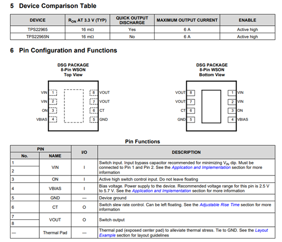
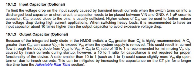
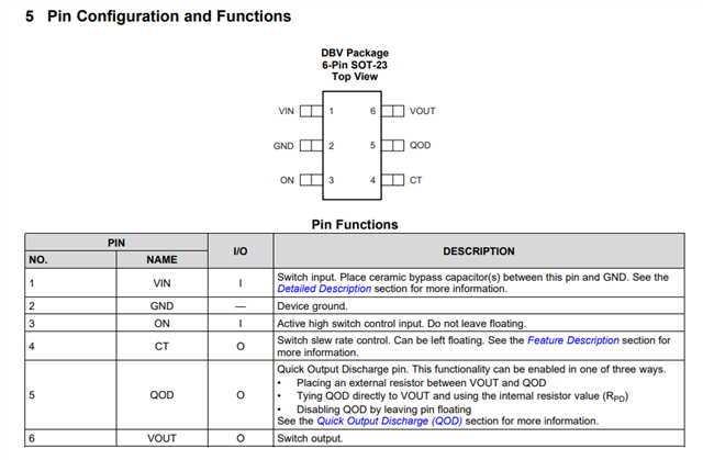
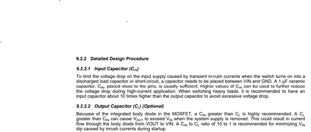
    Refer below input related to eFuse caps and pinout

    TPS22918 5.5-V, 2-A, 52-mΩ On-Resistance Load Switch

    Regards,

    Sreenivasa

  • Hi Board designers, 

    Refer below input related PMIC

     https://e2e.ti.com/support/power-management-group/power-management/f/power-management-forum/1499036/tps65214-i-want-to-know-the-reason-and-solution-for-this-inability-to-output-normally 

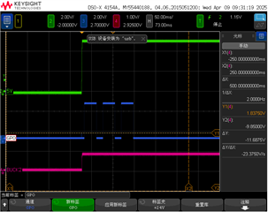
    Hello, I am testing the TPS6521402 chip and encountered the following situation during the testing process, which caused the PMIC to fail to start. Can you help analyze the reason?
    ① EN/MODE/VSEL three pins are pulled up to 3.3V with the power supply
    ② The GPO pin is connected to the power supply through a pull-up resistor, but during the power up process, there are three periodic pulses that continue to output a low level
    ③ As a result, BUCK2 outputs 0.8V, while the other power sources do not output voltage
    ④ The above tests were conducted under no-load conditions
    ⑤ Please refer to the test image below for details

    Since PMIC is not able to complete the power cycle, it tried to power up total of 3 times. Are all the necessary output components are populated for all the rails?

    I have already solved this problem. The voltage was pulled down somewhere in BUCK2, causing the feedback of BUCK2 to not meet the requirements, which in turn activated the PMIC protection mechanism, resulting in no output. Thank you very much for your reminder.

    Main differences between TPS6521401 and TPS6521402:

    • Both are designed to pair with AM62L, but TPS6521402 is a bit more flexible than TPS6521401, in that it can be used to support either LPDDR4 or DDR4.
      TPS6521401 can only support LPDDR4.

    • Based on this, Buck3 voltage is fixed to 1.1 V in -01 version. GPIO/VSEL is configured as GPIO pin.
    • In -02 version, Buck3 voltage can be configured between 1.2 V ( for DDR) , 1.1 V ( for LPDDR) , or 3.3 V with GPIO/VSEL configured as VSEL pin.

    • LDO2 is set to 0.75V to power RTC core in -01.
    • LDO2 is set to 2.5V to support DDR4 (VPP) in -02.
       
    • Timing length is also slightly changed.
    • Timing sequence of all bucks and LDOs is the same, but timing of GPO & GPIO is changed.

    In case you are planning to use DDR4 in your design and would want to implement the power architecture based on TPS6521402, please work with the TI filed team supporting you for additional information.

    Regards,

    Sreenivasa