This thread has been locked.

If you have a related question, please click the "Ask a related question" button in the top right corner. The newly created question will be automatically linked to this question.

AM6442: mcspi on m4f

Part Number: AM6442
Other Parts Discussed in Thread: SYSCONFIG

Tool/software:

Hello TI Expert

These are my configuration

1- 2X MCPI Controller by M4F

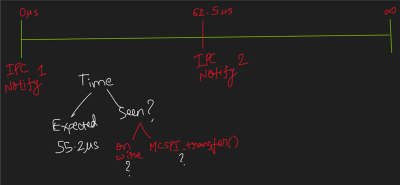
2-At every 62.5us , M4F will receive IPCNotify from R5F00

4-Each MCSPI needs to transmit 22bytes of unique data  on each IPCNotify

5-SCLK is 10MHz

7- MCSPI0 is bidirectional, At the end of transmission m4f needs to process data from MSCPI0 peripheral

6-Both MCSPI must complete transmission before the next IPCNotify , with MCSPI0 needs to complete data processing as well

8 - I have configured both MCSPI using HLD , Interrupt Driven and non blocking. 

If we do rough calculation , 

22*8 = 176bits * 0.1us = 17.6us + CS enable(5us estimated ) +Disable  (5s estimated ) = 27.6us. 

Even with blocking , we should be able to complete transmission within 55.2us

Being non blocking , the  MSCPI1 can start transmitting while MCSPI0 is transmitting, thus it should have more than enough time to complete both transmission

So far I have not been able to get both MSCPI to complete transmission within 62.5us

Is there any configuration/settings that speed up the MSCPI transmission

Thank you

Alan I

  • Hi Alan,

    Thank you for writing the description so precise and clear.

    Allow me sometime to put forward an explanation where I will seek answers to further questions from my end.

    Respectfully,

    Vaibhav

  • Hi Alan,

    Please let me know the time seen on the wire for both the MCSPI0 and MCSPI1 instances.

    Additionally, put out the time for the MCSPI_transfer() API call as well for both MCSPI0 and MCSPI1 instance.

    If the wire transmission time(which can be seen via logic analyzer) is  not available, it is okay and you can go ahead and give me the time for the second ask.

    Respectfully,

    Vaibhav

  • Hello Vaibhav

    Below is what I saw in our current system

    MSCPI0 Init happens  ~0us 

    MCSP1 Init happens at ~6us

    MCSPI0 Call back at ~54us

    MCSPI1 call back at ~65us

    Thanks

    Alan I

  • Hi Alan,

    Please help me with the few more information.

    MCSPI0 Call back at ~54us

    Is the callback initiated at 54 us or the callback is completely executed at 54 us?

    Regards,

    Vaibhav

  • Hi Vaibhav

    MCSPI0 call back starts at 53us

    MCSPI0 call back ends at 54us

    Thanks

    Alan I

  • Hi Alan,

    The transaction of MCSPI0 and MCSPI1 are taking place on two different threads?

    Regards,

    Vaibhav

  • Hi Vaibhav

    I am running bare metal , single thread

    Alan I

  • Hi Alan,

    Please send me the sysconfig settings for both the MCSPIs, a screenshot would do as well.

    Regards,

    Vaibhav

  • /**
    * These arguments were used when this file was generated. They will be automatically applied on subsequent loads
    * via the GUI or CLI. Run CLI with '--help' for additional information on how to override these arguments.
    * @cliArgs --device "AM64x" --package "ALV" --part "Default" --context "m4fss0-0" --product "MCU_PLUS_SDK_AM64x@09.02.01"
    * @versions {"tool":"1.20.0+3587"}
    */

    /**
    * Import the modules used in this configuration.
    */
    const ipc = scripting.addModule("/drivers/ipc/ipc");
    const mcspi = scripting.addModule("/drivers/mcspi/mcspi", {}, false);
    const mcspi1 = mcspi.addInstance();
    const mcspi2 = mcspi.addInstance();
    const addr_translate = scripting.addModule("/kernel/dpl/addr_translate", {}, false);
    const addr_translate1 = addr_translate.addInstance();
    const addr_translate2 = addr_translate.addInstance();
    const addr_translate3 = addr_translate.addInstance();
    const addr_translate4 = addr_translate.addInstance();
    const clock = scripting.addModule("/kernel/dpl/clock");
    const debug_log = scripting.addModule("/kernel/dpl/debug_log");
    const mpu_armv7 = scripting.addModule("/kernel/dpl/mpu_armv7", {}, false);
    const mpu_armv71 = mpu_armv7.addInstance();
    const mpu_armv72 = mpu_armv7.addInstance();
    const mpu_armv73 = mpu_armv7.addInstance();

    /**
    * Write custom configuration values to the imported modules.
    */
    ipc.r5fss1_0 = "NONE";
    ipc.r5fss1_1 = "NONE";
    ipc.r5fss0_1 = "NONE";
    ipc.r5fss0_0 = "notify";
    ipc.intrPriority = 0;

    mcspi1.$name = "CONFIG_MCSPI0";
    mcspi1.transferMode = "CALLBACK";
    mcspi1.txFifoTrigLevel = 32;
    mcspi1.rxFifoTrigLevel = 32;
    mcspi1.intrPriority = 5;
    mcspi1.transferCallbackFxn = "isr_ch_a_callback";
    mcspi1.MCU_SPI.$assign = "MCU_SPI0";
    mcspi1.mcspiChannel[0].$name = "CONFIG_MCSPI_CH0";
    mcspi1.mcspiChannel[0].frameFormat = "POL0_PHA1";
    mcspi1.mcspiChannel[0].bitRate = 10000000;
    mcspi1.child.$name = "drivers_mcspi_v0_mcspi_v0_template0";

    mcspi2.$name = "CONFIG_MCSPI1";
    mcspi2.transferMode = "CALLBACK";
    mcspi2.txFifoTrigLevel = 32;
    mcspi2.rxFifoTrigLevel = 32;
    mcspi2.intrPriority = 6;
    mcspi2.transferCallbackFxn = "isr_ch_b_callback";
    mcspi2.MCU_SPI.$assign = "MCU_SPI1";
    mcspi2.mcspiChannel[0].$name = "CONFIG_MCSPI_CH1";
    mcspi2.mcspiChannel[0].frameFormat = "POL0_PHA1";
    mcspi2.mcspiChannel[0].bitRate = 10000000;
    mcspi2.mcspiChannel[0].MCU_CSn.$assign = "MCU_UART1_RTSn";
    mcspi2.child.$name = "drivers_mcspi_v0_mcspi_v0_template1";

    addr_translate1.$name = "CONFIG_ADDR_TRANSLATE_REGION0";
    addr_translate1.localAddr = 0x80000000;

    addr_translate2.$name = "CONFIG_ADDR_TRANSLATE_REGION1";
    addr_translate2.systemAddr = 0x20000000;
    addr_translate2.localAddr = 0xA0000000;

    addr_translate3.$name = "CONFIG_ADDR_TRANSLATE_REGION2";
    addr_translate3.systemAddr = 0x40000000;
    addr_translate3.localAddr = 0xC0000000;

    addr_translate4.$name = "CONFIG_ADDR_TRANSLATE_REGION3";
    addr_translate4.systemAddr = 0x60000000;
    addr_translate4.localAddr = 0x60000000;

    debug_log.enableCssLog = false;
    debug_log.enableLogZoneWarning = false;
    debug_log.enableLogZoneError = false;

    mpu_armv71.$name = "CONFIG_MPU_REGION0";
    mpu_armv71.attributes = "Device";
    mpu_armv71.allowExecute = false;

    mpu_armv72.$name = "CONFIG_MPU_REGION1";
    mpu_armv72.size = 18;

    mpu_armv73.$name = "CONFIG_MPU_REGION2";
    mpu_armv73.attributes = "NonCached";
    mpu_armv73.baseAddr = 0x701E0000;
    mpu_armv73.size = 16;
    mpu_armv73.allowExecute = false;

    /**
    * Pinmux solution for unlocked pins/peripherals. This ensures that minor changes to the automatic solver in a future
    * version of the tool will not impact the pinmux you originally saw. These lines can be completely deleted in order to
    * re-solve from scratch.
    */
    mcspi1.MCU_SPI.CLK.$suggestSolution = "MCU_SPI0_CLK";
    mcspi1.MCU_SPI.D0.$suggestSolution = "MCU_SPI0_D0";
    mcspi1.MCU_SPI.D1.$suggestSolution = "MCU_SPI0_D1";
    mcspi1.mcspiChannel[0].MCU_CSn.$suggestSolution = "MCU_SPI0_CS0";
    mcspi2.MCU_SPI.CLK.$suggestSolution = "MCU_SPI1_CLK";
    mcspi2.MCU_SPI.D0.$suggestSolution = "MCU_SPI1_D0";
    mcspi2.MCU_SPI.D1.$suggestSolution = "MCU_SPI1_D1";

  • Hi Alan,

    Thanks for specifying the sysconfig file. Allow me sometime to comment on this.

    Regards,

    Vaibhav

  • Hi Alan,

    I have opened the SysConfig and checked the configurations.

    Can you please try to see if your operations of MCSPI, basically the MCSPI Transfer is happening at frequency of suppose 50 MHz?

    Please let me know.

    Also, I am assuming that we can see timing/latency improvements as well.

    Regards,

    Vaibhav