This thread has been locked.

If you have a related question, please click the "Ask a related question" button in the top right corner. The newly created question will be automatically linked to this question.

PROCESSOR-SDK-AM62X: Microphone Input Not Working on TLV320AIC3204 with AM625x via McASP Interface

Part Number: PROCESSOR-SDK-AM62X
Other Parts Discussed in Thread: TLV320AIC3204, AM6252

Tool/software:

Hi TI Support Team,

We are working on integrating the TLV320AIC3204 audio codec with a TI AM6252 (AM62x) processor over the McASP interface, using Linux kernel v6.1.46 SDK from TI. The speaker output is functioning correctly, but we are facing an issue with the microphone input, which does not capture any audio.

Here are some details:

  • The codec is connected via I2C + McASP.

  • We are using the simple-audio-card in the device tree with widgets and routing defined (similar to what works on our Colibri iMX7D and iMX6ULL platforms).

codec_audio1: sound1 {
        compatible = "simple-audio-card";
        simple-audio-card,name = "AM625x-TLV320AIC3204";        
        simple-audio-card,widgets =
            "Microphone", "Mic Jack",
            "Line", "Line In",
            "Line", "Line Out",
            "Headphone", "Headphone Jack";
            simple-audio-card,routing =
            "IN1_L", "Line In",
            "IN1_R", "Line In",
            "IN3_R", "Mic Jack",
            "CM_L", "Mic Jack",
            "CM_R", "Mic Jack",
            "Line Out", "LOL",
            "Line Out", "LOR",
            "Headphone Jack", "HPL",
            "Headphone Jack", "HPR";                            
        simple-audio-card,format = "i2s";
        simple-audio-card,mclk-fs = <256>;
        simple-audio-card,bitclock-master = <&sound_master1>;
        simple-audio-card,frame-master = <&sound_master1>;
        simple-audio-card,bitclock-inversion;

        simple-audio-card,cpu {
            sound-dai = <&mcasp1>;
        };

        sound_master1: simple-audio-card,codec {
            sound-dai = <&tlv320aic3204>;
            clocks = <&sgtl5000_mclk>;
        };
    };

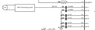
  • The microphone is connected directly (not through a jack) using the IN1_L pin, and speaker output is routed via HP_L.

  • We've reused the same amixer settings and device tree configuration that worked on NXP platforms.

    Any widgets or routing issues for MIC from TLV320AIC3204 to AM6252 via I2S McASP.  ?
  • Hi Shekar,

    Have you tried to change the mic bias voltage and see if it works?

    Please provide what mixer controls are you configuring before arecord command to capture?

    Best Regards,

    Suren

  • Hi Suren,

    We are not using Mic bias just kept NC and we are generating MIC supply externally in our board .

    Please find amixer configurations of TLV320AIC3204 as below:

    root@myd-am62x:~# amixer -c 1 contents
    numid=1,iface=MIXER,name='PCM Playback Volume'
      ; type=INTEGER,access=rw---R--,values=2,min=0,max=175,step=0
      : values=88,88
      | dBscale-min=-63.50dB,step=0.50dB,mute=0
    numid=9,iface=MIXER,name='Mic PGA Switch'
      ; type=BOOLEAN,access=rw------,values=2
      : values=on,on
    numid=12,iface=MIXER,name='ADC Level Volume'
      ; type=INTEGER,access=rw---R--,values=2,min=0,max=64,step=0
      : values=47,47
      | dBscale-min=-12.00dB,step=0.50dB,mute=0
    numid=10,iface=MIXER,name='ADCFGA Left Mute Switch'
      ; type=BOOLEAN,access=rw------,values=1
      : values=off
    numid=11,iface=MIXER,name='ADCFGA Right Mute Switch'
      ; type=BOOLEAN,access=rw------,values=1
      : values=off
    numid=22,iface=MIXER,name='AGC Attack Time'
      ; type=INTEGER,access=rw------,values=2,min=0,max=31,step=0
      : values=0,0
    numid=23,iface=MIXER,name='AGC Decay Time'
      ; type=INTEGER,access=rw------,values=2,min=0,max=31,step=0
      : values=0,0
    numid=18,iface=MIXER,name='AGC Gain Hysteresis'
      ; type=INTEGER,access=rw------,values=2,min=0,max=3,step=0
      : values=0,0
    numid=19,iface=MIXER,name='AGC Hysteresis'
      ; type=INTEGER,access=rw------,values=2,min=0,max=3,step=0
      : values=0,0
    numid=15,iface=MIXER,name='AGC Left Switch'
      ; type=BOOLEAN,access=rw------,values=1
      : values=off
    numid=21,iface=MIXER,name='AGC Max PGA'
      ; type=INTEGER,access=rw------,values=2,min=0,max=127,step=0
      : values=127,127
    numid=24,iface=MIXER,name='AGC Noise Debounce'
      ; type=INTEGER,access=rw------,values=2,min=0,max=31,step=0
      : values=0,0
    numid=20,iface=MIXER,name='AGC Noise Threshold'
      ; type=INTEGER,access=rw------,values=2,min=0,max=31,step=0
      : values=0,0
    numid=16,iface=MIXER,name='AGC Right Switch'
      ; type=BOOLEAN,access=rw------,values=1
      : values=off
    numid=25,iface=MIXER,name='AGC Signal Debounce'
      ; type=INTEGER,access=rw------,values=2,min=0,max=15,step=0
      : values=0,0
    numid=17,iface=MIXER,name='AGC Target Level'
      ; type=INTEGER,access=rw------,values=2,min=0,max=7,step=0
      : values=0,0
    numid=14,iface=MIXER,name='Auto-mute Switch'
      ; type=INTEGER,access=rw------,values=1,min=0,max=7,step=0
      : values=0
    numid=43,iface=MIXER,name='CM_L to Left Mixer Negative Resistor'
      ; type=ENUMERATED,access=rw------,values=1,items=4
      ; Item #0 'Off'
      ; Item #1 '10 kOhm'
      ; Item #2 '20 kOhm'
      ; Item #3 '40 kOhm'
      : values=1
    numid=36,iface=MIXER,name='CM_R to Right Mixer Negative Resistor'
      ; type=ENUMERATED,access=rw------,values=1,items=4
      ; Item #0 'Off'
      ; Item #1 '10 kOhm'
      ; Item #2 '20 kOhm'
      ; Item #3 '40 kOhm'
      : values=1
    numid=2,iface=MIXER,name='DAC Left Playback PowerTune Switch'
      ; type=ENUMERATED,access=rw------,values=1,items=3
      ; Item #0 'P3'
      ; Item #1 'P2'
      ; Item #2 'P1'
      : values=0
    numid=3,iface=MIXER,name='DAC Right Playback PowerTune Switch'
      ; type=ENUMERATED,access=rw------,values=1,items=3
      ; Item #0 'P3'
      ; Item #1 'P2'
      ; Item #2 'P1'
      : values=2
    numid=6,iface=MIXER,name='HP DAC Playback Switch'
      ; type=BOOLEAN,access=rw------,values=2
      : values=on,on
    numid=4,iface=MIXER,name='HP Driver Gain Volume'
      ; type=INTEGER,access=rw---R--,values=2,min=0,max=35,step=0
      : values=3,3
      | dBscale-min=-6.00dB,step=1.00dB,mute=0
    numid=27,iface=MIXER,name='HPL Output Mixer IN1_L Switch'
      ; type=BOOLEAN,access=rw------,values=1
      : values=off
    numid=26,iface=MIXER,name='HPL Output Mixer L_DAC Switch'
      ; type=BOOLEAN,access=rw------,values=1
      : values=on
    numid=30,iface=MIXER,name='HPR Output Mixer IN1_R Switch'
      ; type=BOOLEAN,access=rw------,values=1
      : values=off
    numid=29,iface=MIXER,name='HPR Output Mixer R_DAC Switch'
      ; type=BOOLEAN,access=rw------,values=1
      : values=off
    numid=39,iface=MIXER,name='IN1_L to Left Mixer Positive Resistor'
      ; type=ENUMERATED,access=rw------,values=1,items=4
      ; Item #0 'Off'
      ; Item #1 '10 kOhm'
      ; Item #2 '20 kOhm'
      ; Item #3 '40 kOhm'
      : values=1
    numid=37,iface=MIXER,name='IN1_L to Right Mixer Negative Resistor'
      ; type=ENUMERATED,access=rw------,values=1,items=4
      ; Item #0 'Off'
      ; Item #1 '10 kOhm'
      ; Item #2 '20 kOhm'
      ; Item #3 '40 kOhm'
      : values=0
    numid=42,iface=MIXER,name='IN1_R to Left Mixer Positive Resistor'
      ; type=ENUMERATED,access=rw------,values=1,items=4
      ; Item #0 'Off'
      ; Item #1 '10 kOhm'
      ; Item #2 '20 kOhm'
      ; Item #3 '40 kOhm'
      : values=0
    numid=32,iface=MIXER,name='IN1_R to Right Mixer Positive Resistor'
      ; type=ENUMERATED,access=rw------,values=1,items=4
      ; Item #0 'Off'
      ; Item #1 '10 kOhm'
      ; Item #2 '20 kOhm'
      ; Item #3 '40 kOhm'
      : values=0
    numid=40,iface=MIXER,name='IN2_L to Left Mixer Positive Resistor'
      ; type=ENUMERATED,access=rw------,values=1,items=4
      ; Item #0 'Off'
      ; Item #1 '10 kOhm'
      ; Item #2 '20 kOhm'
      ; Item #3 '40 kOhm'
      : values=0
    numid=35,iface=MIXER,name='IN2_L to Right Mixer Positive Resistor'
      ; type=ENUMERATED,access=rw------,values=1,items=4
      ; Item #0 'Off'
      ; Item #1 '10 kOhm'
      ; Item #2 '20 kOhm'
      ; Item #3 '40 kOhm'
      : values=0
    numid=44,iface=MIXER,name='IN2_R to Left Mixer Negative Resistor'
      ; type=ENUMERATED,access=rw------,values=1,items=4
      ; Item #0 'Off'
      ; Item #1 '10 kOhm'
      ; Item #2 '20 kOhm'
      ; Item #3 '40 kOhm'
      : values=0
    numid=33,iface=MIXER,name='IN2_R to Right Mixer Positive Resistor'
      ; type=ENUMERATED,access=rw------,values=1,items=4
      ; Item #0 'Off'
      ; Item #1 '10 kOhm'
      ; Item #2 '20 kOhm'
      ; Item #3 '40 kOhm'
      : values=0
    numid=41,iface=MIXER,name='IN3_L to Left Mixer Positive Resistor'
      ; type=ENUMERATED,access=rw------,values=1,items=4
      ; Item #0 'Off'
      ; Item #1 '10 kOhm'
      ; Item #2 '20 kOhm'
      ; Item #3 '40 kOhm'
      : values=0
    numid=38,iface=MIXER,name='IN3_L to Right Mixer Negative Resistor'
      ; type=ENUMERATED,access=rw------,values=1,items=4
      ; Item #0 'Off'
      ; Item #1 '10 kOhm'
      ; Item #2 '20 kOhm'
      ; Item #3 '40 kOhm'
      : values=0
    numid=45,iface=MIXER,name='IN3_R to Left Mixer Negative Resistor'
      ; type=ENUMERATED,access=rw------,values=1,items=4
      ; Item #0 'Off'
      ; Item #1 '10 kOhm'
      ; Item #2 '20 kOhm'
      ; Item #3 '40 kOhm'
      : values=0
    numid=34,iface=MIXER,name='IN3_R to Right Mixer Positive Resistor'
      ; type=ENUMERATED,access=rw------,values=1,items=4
      ; Item #0 'Off'
      ; Item #1 '10 kOhm'
      ; Item #2 '20 kOhm'
      ; Item #3 '40 kOhm'
      : values=0
    numid=7,iface=MIXER,name='LO DAC Playback Switch'
      ; type=BOOLEAN,access=rw------,values=2
      : values=on,on
    numid=5,iface=MIXER,name='LO Driver Gain Volume'
      ; type=INTEGER,access=rw---R--,values=2,min=0,max=35,step=0
      : values=16,16
      | dBscale-min=-6.00dB,step=1.00dB,mute=0
    numid=8,iface=MIXER,name='LO Playback Common Mode Switch'
      ; type=ENUMERATED,access=rw------,values=1,items=2
      ; Item #0 'Full Chip'
      ; Item #1 '1.65V'
      : values=0
    numid=28,iface=MIXER,name='LOL Output Mixer L_DAC Switch'
      ; type=BOOLEAN,access=rw------,values=1
      : values=off
    numid=31,iface=MIXER,name='LOR Output Mixer R_DAC Switch'
      ; type=BOOLEAN,access=rw------,values=1
      : values=off
    numid=13,iface=MIXER,name='PGA Level Volume'
      ; type=INTEGER,access=rw---R--,values=2,min=0,max=95,step=0
      : values=50,50
      | dBscale-min=0.00dB,step=0.50dB,mute=0
    root@myd-am62x:~#

  • Hi Nuthula Shekar,

    I see that you have configured IN1_L mixer control and not the other Line In related controls? 

    Can you try using amixer cset commands to set those and also try changing the resistors to 20kohm resistors and see if it helps.

    Also please refer the below Reference application guide for Audio codec:

    https://www.ti.com/lit/ml/slaa557/slaa557.pdf

    Best Regards,

    Suren

  • Hi Suren, 

    I have mentioned all the amixer controls that I am able to see. Could you please be more specific about what else needs to be modified? I have also changed the resistor to 20k, but it is still not working.

  • Hi,

    Can you attach your schematic here as well? I notice that you have the Right Mixer negative resistor set to CM, but nothing on the positive side. I see that you have the left mixer positive and negative set up correctly for IN1L on the left ADC. Can you attach a register dump of the AIC3204? Also, can you make sure that there is a signal output at the IN1L pin on a scope?

    Best,
    Mir

  • Hi Mir ,

    please find reg content as follow as

    root@myd-am62x:~# i2cdump -y -f 2 0x18
    No size specified (using byte-data access)
         0  1  2  3  4  5  6  7  8  9  a  b  c  d  e  f    0123456789abcdef
    00: 00 00 50 00 03 11 08 1b a2 00 00 08 02 00 80 02    ..P.?????..??.??
    10: 00 08 08 02 80 01 00 04 00 00 01 0c 00 01 04 00    .?????.?..??.??.
    20: 00 00 00 00 44 00 11 00 00 00 00 00 00 00 00 00    ....D.?.........
    30: 00 00 00 00 00 12 03 02 02 00 00 00 01 01 00 14    .....????...??.?
    40: 0c d8 d8 00 6f 38 00 00 00 00 00 ee 10 d8 7e e3    ???.o8.....???~?
    50: 00 00 00 00 00 00 00 00 7f 00 00 00 00 00 00 00    ........?.......
    60: 7f 00 00 00 00 00 00 00 00 00 00 00 00 00 00 00    ?...............
    70: 00 00 00 00 00 00 00 00 00 00 00 00 00 00 00 00    ................
    80: 00 00 00 00 00 00 00 00 00 00 00 00 00 00 00 00    ................
    90: 00 00 00 00 00 00 00 00 00 00 00 00 00 00 00 00    ................
    a0: 00 00 00 00 00 00 00 00 00 00 00 00 00 00 00 00    ................
    b0: 00 00 00 00 00 00 00 00 00 00 00 00 00 00 00 00    ................
    c0: 00 00 00 00 00 00 00 00 00 00 00 00 00 00 00 00    ................
    d0: 00 00 00 00 00 00 00 00 00 00 00 00 00 00 00 00    ................
    e0: 00 00 00 00 00 00 00 00 00 00 00 00 00 00 00 00    ................
    f0: 00 00 00 00 00 00 00 00 00 00 00 00 00 00 00 00    ................
    root@myd-am62x:~#

    and there is no signal on In1_L pin . Schematic is shared with your TI team via mail to Lakshmi narashimhan and  Anatya vallabh.

  • Shekar,

    I didn't understand what you mean by there is no signal on IN1_L PIN.

    - Can you take a look at the schematic shared via email?

    Best Regards,

    Suren

  • Hi,

    Here is the input circuit from the schematic shared via email. If you are not getting any signal at the IN1L pin, then there may be an issue with the "mic processing circuit" shown here. From the amixer configuration, it shows you are expecting signal on the IN1L pin, and the schematic shows this as well. Can you show what the mic processing circuit is so we can help figure out why you are not getting a mic signal?

    Best,
    Mir

  • Hi Mir,

    The mic processing circuit is working with other NXP-based processors using the same TLV320AIC3204 device; however, it is failing in this case. When I try to record using arecord with the TI AM6252, there is no signal on the DOUT pin, whereas with other processors, I can see activity on the DOUT line .

  • Hi Nuthula, 

    Please share the DTS file to review the MCASP configurations you are setting.

    Best Regards,

    Suren

  • Hi Suren ,

    Please find the dts file

    // SPDX-License-Identifier: GPL-2.0
    /*
     * Common dtsi for AM62x SK and derivatives
     *
     * Copyright (C) 2021-2023 Texas Instruments Incorporated - https://www.ti.com/
     */

    #include <dt-bindings/leds/common.h>
    #include <dt-bindings/gpio/gpio.h>
    #include <dt-bindings/net/ti-dp83867.h>
    #include <dt-bindings/input/input.h>
    #include "k3-am625.dtsi"

    / {
        aliases {
            serial2 = &main_uart0;
            serial3 = &main_uart1;
            serial6 = &main_uart4;
            serial8 = &main_uart6;
            mmc0 = &sdhci0;
            mmc1 = &sdhci1;
            mmc2 = &sdhci2;
            spi0 = &ospi0;
            ethernet0 = &cpsw_port1;
            ethernet1 = &cpsw_port2;
            usb0 = &usb0;
            usb1 = &usb1;
        };

        chosen {
            stdout-path = "serial2:115200n8";
            bootargs = "console=ttyS2,115200n8 earlycon=ns16550a,mmio32,0x02800000";
        };

        opp-table {
            /* Add 1.4GHz OPP for am625-sk board. Requires VDD_CORE to be at 0.85V */
            opp-1400000000 {
                opp-hz = /bits/ 64 <1400000000>;
                opp-supported-hw = <0x01 0x0004>;
                clock-latency-ns = <6000000>;
            };
        };

        memory@80000000 {
            device_type = "memory";
            /* 2G RAM */
            reg = <0x00000000 0x80000000 0x00000000 0x80000000>;

        };

        reserved-memory {
            #address-cells = <2>;
            #size-cells = <2>;
            ranges;

            ramoops@9c700000 {
                compatible = "ramoops";
                reg = <0x00 0x9c700000 0x00 0x00100000>;
                record-size = <0x8000>;
                console-size = <0x8000>;
                ftrace-size = <0x00>;
                pmsg-size = <0x8000>;
            };


            rtos_ipc_memory_region: ipc-memories@9c800000 {
                compatible = "shared-dma-pool";
                reg = <0x00 0x9c800000 0x00 0x00300000>;
                no-map;
            };

            mcu_m4fss_dma_memory_region: m4f-dma-memory@9cb00000 {
                compatible = "shared-dma-pool";
                reg = <0x00 0x9cb00000 0x00 0x100000>;
                no-map;
            };

            mcu_m4fss_memory_region: m4f-memory@9cc00000 {
                compatible = "shared-dma-pool";
                reg = <0x00 0x9cc00000 0x00 0xe00000>;
                no-map;
            };

            wkup_r5fss0_core0_dma_memory_region: r5f-dma-memory@9da00000 {
                compatible = "shared-dma-pool";
                reg = <0x00 0x9da00000 0x00 0x00100000>;
                no-map;
            };

            wkup_r5fss0_core0_memory_region: r5f-memory@9db00000 {
                compatible = "shared-dma-pool";
                reg = <0x00 0x9db00000 0x00 0x00c00000>;
                no-map;
            };

            lpm_ctx_ddr: lpm-memory@9e700000 {
                reg = <0x00 0x9e700000 0x00 0x80000>;
                alignment = <0x1000>;
            };

            secure_tfa_ddr: tfa@9e780000 {
                reg = <0x00 0x9e780000 0x00 0x80000>;
                alignment = <0x1000>;
                no-map;
            };

            secure_ddr: optee@9e800000 {
                reg = <0x00 0x9e800000 0x00 0x01800000>; /* for OP-TEE */
                alignment = <0x1000>;
                no-map;
            };

            framebuffer: framebuffer@ff700000 {
                reg = <0x00 0xff700000 0x00 0x008ca000>;
                no-map;
            };
        };

        vmain_pd: regulator-0 {
            compatible = "regulator-fixed";
            regulator-name = "vmain_pd";
            regulator-min-microvolt = <5000000>;
            regulator-max-microvolt = <5000000>;
            regulator-always-on;
            regulator-boot-on;
        };

        vcc_5v0: regulator-1 {
            compatible = "regulator-fixed";
            regulator-name = "vcc_5v0";
            regulator-min-microvolt = <5000000>;
            regulator-max-microvolt = <5000000>;
            vin-supply = <&vmain_pd>;
            regulator-always-on;
            regulator-boot-on;
        };

        vcc_3v3_sys: regulator-2 {
            compatible = "regulator-fixed";
            regulator-name = "vcc_3v3_sys";
            regulator-min-microvolt = <3300000>;
            regulator-max-microvolt = <3300000>;
            vin-supply = <&vmain_pd>;
            regulator-always-on;
            regulator-boot-on;
        };

        vdd_mmc1: regulator-3 {
            compatible = "regulator-fixed";
            regulator-name = "vdd_mmc1";
            regulator-min-microvolt = <3300000>;
            regulator-max-microvolt = <3300000>;
            regulator-boot-on;
            enable-active-high;
            vin-supply = <&vcc_3v3_sys>;
        };

        vdd_sd_dv: regulator-sd {
            compatible = "regulator-fixed";
            regulator-name = "vdd_sd_dv";
            regulator-min-microvolt = <3300000>;
            regulator-max-microvolt = <3300000>;
            regulator-boot-on;
            enable-active-high;
            vin-supply = <&vcc_3v3_sys>;
        };

        vdd_wl_dv: regulator-wl {
            compatible = "regulator-fixed";
            regulator-name = "vdd_wl_dv";
            regulator-min-microvolt = <3300000>;
            regulator-max-microvolt = <3300000>;
            regulator-boot-on;
            enable-active-high;
            vin-supply = <&vcc_3v3_sys>;
        };

        wlan_reg_on: regulator-4 {
            compatible = "regulator-fixed";
            regulator-name = "wlan_reg_on";
            regulator-min-microvolt = <3300000>;
            regulator-max-microvolt = <3300000>;
            enable-active-high;
            regulator-boot-on;
            vin-supply = <&vcc_3v3_sys>;
            pinctrl-names = "default";
            pinctrl-1 = <&mcu_wlan_reg_on_pins_default>;
            gpios = <&mcu_gpio0 15 GPIO_ACTIVE_HIGH>;
        };

        vcc_1v8: regulator-5 {
            compatible = "regulator-fixed";
            regulator-name = "vcc_1v8";
            regulator-min-microvolt = <1800000>;
            regulator-max-microvolt = <1800000>;
            vin-supply = <&vcc_3v3_sys>;
            regulator-always-on;
            regulator-boot-on;
        };

        lvds_power: regulator-6 {
            compatible = "regulator-fixed";
            regulator-name = "lvds_power";
            regulator-min-microvolt = <3300000>;
            regulator-max-microvolt = <3300000>;
            enable-active-high;
            regulator-always-on;
            regulator-boot-on;
            vin-supply = <&vcc_5v0>;
            pinctrl-names = "default";
            pinctrl-1 = <&mcu_lvds_power_pins_default>;
            gpios = <&mcu_gpio0 4 GPIO_ACTIVE_HIGH>;
        };

        csi1_io: csi1-io {
            compatible = "regulator-fixed";
            regulator-name = "csi1_pwr";
            regulator-min-microvolt = <3300000>;
            regulator-max-microvolt = <3300000>;
            gpio = <&mcu_gpio0 3 GPIO_ACTIVE_HIGH>;
            enable-active-high;
            regulator-always-on;
            pinctrl-names = "default";
            pinctrl-1 = <&csi_io_power_pins_default>;
        };


        hdmi: connector {
            compatible = "hdmi-connector";
            label = "hdmi";
            type = "a";
            port {
                hdmi_connector_in: endpoint {
                    remote-endpoint = <&sii9022_out>;
                };
            };
        };

        clk_ov5640_fixed: ov5640-xclk {
            compatible = "fixed-clock";
            #clock-cells = <0>;
            clock-frequency = <12000000>;
        };

        sgtl5000_mclk: sgtl5000-mclk {
            compatible = "fixed-clock";
            #clock-cells = <0>;
            clock-frequency = <11289600>;
        };

        codec_audio: sound {
            compatible = "simple-audio-card";
            simple-audio-card,name = "AM62x-SKEVM";
            simple-audio-card,widgets =
                    "Microphone", "Microphone Jack",
                    "Headphone", "Headphone Jack",
                    "Speaker", "Speaker Ext",
                    "Line", "Line In Jack";
            simple-audio-card,routing =
                    "MIC_IN", "Microphone Jack",
                    "Microphone Jack", "Mic Bias",
                    "LINE_IN", "Line In Jack",
                    "Headphone Jack", "HP_OUT",
                    "Speaker Ext", "LINE_OUT";
            simple-audio-card,format = "i2s";
            simple-audio-card,mclk-fs = <256>;
            simple-audio-card,bitclock-master = <&sound_master>;
            simple-audio-card,frame-master = <&sound_master>;
            simple-audio-card,bitclock-inversion;

            simple-audio-card,cpu {
                sound-dai = <&mcasp0>;
            };

            sound_master: simple-audio-card,codec {
                sound-dai = <&sgtl5000>;
                clocks = <&sgtl5000_mclk>;
            };
        };

           
           codec_audio1: sound1 {
            compatible = "simple-audio-card";
            simple-audio-card,name = "AM625x-TLV320AIC3204";        
            simple-audio-card,widgets =
            //    "Microphone", "Mic Jack",
            //    "Headphone", "Headphone Jack";
                "Line", "Line In",
                "Line", "Line Out";

                simple-audio-card,routing =
                "Line Out", "HPL",
                "Line Out", "HPR",
                "IN1_L", "Line In",
                "IN1_R", "Line In";
            //    "IN1_L", "Mic Jack",
            //    "IN1_R", "Mic Jack",
            //    "Headphone Jack", "HPL",
            //    "Headphone Jack", "HPR";                            
            simple-audio-card,format = "i2s";
            simple-audio-card,mclk-fs = <256>;
            simple-audio-card,bitclock-master = <&sound_master1>;
            simple-audio-card,frame-master = <&sound_master1>;
            simple-audio-card,bitclock-inversion;

            simple-audio-card,cpu {
                sound-dai = <&mcasp1>;
            };

            sound_master1: simple-audio-card,codec {
                sound-dai = <&tlv320aic3204>;
                clocks = <&sgtl5000_mclk>;
            };
        };


        leds {
            compatible = "gpio-leds";

            led-user {
                label = "am62-sk:d54";
                gpios = <&at9555 4 GPIO_ACTIVE_LOW>;
                max-brightness = <255>;
                linux,default-trigger = "heartbeat";
                function = LED_FUNCTION_HEARTBEAT;
                default-state = "off";
            };

            led-sys {
                label = "am62-sk:d53";
                pinctrl-names = "default";
                pinctrl-1 = <&mcu_run_led_pins_default>;
                gpios = <&mcu_gpio0 16 GPIO_ACTIVE_LOW>;
                linux,default-trigger = "heartbeat";
                function = LED_FUNCTION_HEARTBEAT;
                default-state = "on";
            };
        };

        gpio-keys {
            compatible = "gpio-keys";
            autorepeat;
            pinctrl-names = "default";
            pinctrl-0 = <&main_user_key_pins_default>;

            user: user {
                label = "GPIO Key USER1";
                linux,code = <BTN_0>;
                gpios = <&main_gpio0 36 GPIO_ACTIVE_LOW>;
            };
        };
    };

    &main_pmx0 {
        /* First pad number is ALW package and second is AMC package */
        main_uart0_pins_default: main-uart0-pins-default {
            pinctrl-single,pins = <
                AM62X_IOPAD(0x1c8, PIN_INPUT, 0) /* (D14/A13) UART0_RXD */
                AM62X_IOPAD(0x1cc, PIN_OUTPUT, 0) /* (E14/E11) UART0_TXD */
            >;
        };

        main_uart1_pins_default: main-uart1-pins-default {
            pinctrl-single,pins = <
                AM62X_IOPAD(0x0194, PIN_INPUT, 2) /* (B19) MCASP0_AXR3.UART1_CTSn */
                AM62X_IOPAD(0x0198, PIN_OUTPUT, 2) /* (A19) MCASP0_AXR2.UART1_RTSn */
                AM62X_IOPAD(0x01ac, PIN_INPUT, 2) /* (E19) MCASP0_AFSR.UART1_RXD */
                AM62X_IOPAD(0x01b0, PIN_OUTPUT, 2) /* (A20) MCASP0_ACLKR.UART1_TXD */
            >;
        };

        main_uart4_pins_default: main-uart4-pins-default {
            pinctrl-single,pins = <
                AM62X_IOPAD(0x00b0, PIN_INPUT, 3) /* (K22) GPMC0_CSn2.UART4_RXD */
                AM62X_IOPAD(0x00b4, PIN_OUTPUT, 3) /* (K24) GPMC0_CSn3.UART4_TXD */
            >;
        };

        main_uart4_rst_pins_default: main-uart4-rst-pins-default {
            pinctrl-single,pins = <
                AM62X_IOPAD(0x0030, PIN_INPUT, 7) /* (G21) OSPI0_CSn1.GPIO0_12 */
            >;
        };

        main_uart6_pins_default: main-uart6-pins-default {
            pinctrl-single,pins = <
                AM62X_IOPAD(0x009c, PIN_INPUT, 3) /* (V25) GPMC0_WAIT1.UART6_RXD */
                AM62X_IOPAD(0x00a0, PIN_OUTPUT, 3) /* (K25) GPMC0_WPn.UART6_TXD */
            >;
        };

        main_uart6_rst_pins_default: main-uart6-rst-pins-default {
            pinctrl-single,pins = <
                AM62X_IOPAD(0x0258, PIN_INPUT, 7) /* (F18) USB1_DRVVBUS.GPIO1_51 */
            >;
        };

        main_i2c0_pins_default: main-i2c0-pins-default {
            pinctrl-single,pins = <
                AM62X_IOPAD(0x1e0, PIN_INPUT_PULLUP, 0) /* (B16/E12) I2C0_SCL */
                AM62X_IOPAD(0x1e4, PIN_INPUT_PULLUP, 0) /* (A16/D14) I2C0_SDA */
            >;
        };

        main_i2c1_pins_default: main-i2c1-pins-default {
            pinctrl-single,pins = <
                AM62X_IOPAD(0x1e8, PIN_INPUT_PULLUP, 0) /* (B17/A17) I2C1_SCL */
                AM62X_IOPAD(0x1ec, PIN_INPUT_PULLUP, 0) /* (A17/A16) I2C1_SDA */
            >;
        };

        main_i2c3_pins_default: main-i2c3-pins-default {
            pinctrl-single,pins = <
                AM62X_IOPAD(0x1d0, PIN_INPUT_PULLUP, 2) /* (A15) UART0_CTSn.I2C3_SCL */
                AM62X_IOPAD(0x1d4, PIN_INPUT_PULLUP, 2) /* (B15) UART0_RTSn.I2C3_SDA */
            >;
        };

        main_mmc0_pins_default: main-mmc0-pins-default {
            pinctrl-single,pins = <
                AM62X_IOPAD(0x220, PIN_INPUT, 0) /* (Y3/V3) MMC0_CMD */
                AM62X_IOPAD(0x218, PIN_INPUT, 0) /* (AB1/Y1) MMC0_CLK */
                AM62X_IOPAD(0x214, PIN_INPUT, 0) /* (AA2/V2) MMC0_DAT0 */
                AM62X_IOPAD(0x210, PIN_INPUT, 0) /* (AA1/V1) MMC0_DAT1 */
                AM62X_IOPAD(0x20c, PIN_INPUT, 0) /* (AA3/W2) MMC0_DAT2 */
                AM62X_IOPAD(0x208, PIN_INPUT, 0) /* (Y4/W1) MMC0_DAT3 */
                AM62X_IOPAD(0x204, PIN_INPUT, 0) /* (AB2/Y2) MMC0_DAT4 */
                AM62X_IOPAD(0x200, PIN_INPUT, 0) /* (AC1/W3) MMC0_DAT5 */
                AM62X_IOPAD(0x1fc, PIN_INPUT, 0) /* (AD2/W4) MMC0_DAT6 */
                AM62X_IOPAD(0x1f8, PIN_INPUT, 0) /* (AC2/V4) MMC0_DAT7 */
            >;
        };

        main_mmc1_pins_default: main-mmc1-pins-default {
            pinctrl-single,pins = <
                AM62X_IOPAD(0x23c, PIN_INPUT, 0) /* (A21/C18) MMC1_CMD */
                AM62X_IOPAD(0x234, PIN_INPUT, 0) /* (B22/A20) MMC1_CLK */
                AM62X_IOPAD(0x230, PIN_INPUT, 0) /* (A22/A19) MMC1_DAT0 */
                AM62X_IOPAD(0x22c, PIN_INPUT, 0) /* (B21/B19) MMC1_DAT1 */
                AM62X_IOPAD(0x228, PIN_INPUT, 0) /* (C21/B20) MMC1_DAT2 */
                AM62X_IOPAD(0x224, PIN_INPUT, 0) /* (D22/C19) MMC1_DAT3 */
                AM62X_IOPAD(0x240, PIN_INPUT, 0) /* (D17/C15) MMC1_SDCD */
            >;
        };

        main_mmc2_pins_default: main-mmc2-pins-default {
            pinctrl-single,pins = <
                AM62X_IOPAD(0x120, PIN_INPUT, 0) /* (C24) MMC2_CMD */
                AM62X_IOPAD(0x118, PIN_INPUT, 0) /* (D25) MMC2_CLK */
                AM62X_IOPAD(0x114, PIN_INPUT, 0) /* (B24) MMC2_DAT0 */
                AM62X_IOPAD(0x110, PIN_INPUT, 0) /* (C25) MMC2_DAT1 */
                AM62X_IOPAD(0x10c, PIN_INPUT, 0) /* (E23) MMC2_DAT2 */
                AM62X_IOPAD(0x108, PIN_INPUT, 0) /* (D24) MMC2_DAT3 */
                AM62X_IOPAD(0x11c, PIN_INPUT, 0) /* (#N/A) MMC2_CLKB */
            >;
        };

        main_mdio1_pins_default: main-mdio1-pins-default {
            pinctrl-single,pins = <
                AM62X_IOPAD(0x160, PIN_OUTPUT, 0) /* (AD24/V17) MDIO0_MDC */
                AM62X_IOPAD(0x15c, PIN_INPUT, 0) /* (AB22/U16) MDIO0_MDIO */
            >;
        };

        main_rgmii1_pins_default: main-rgmii1-pins-default {
            pinctrl-single,pins = <
                AM62X_IOPAD(0x14c, PIN_INPUT, 0) /* (AB17/W15) RGMII1_RD0 */
                AM62X_IOPAD(0x150, PIN_INPUT, 0) /* (AC17/Y16) RGMII1_RD1 */
                AM62X_IOPAD(0x154, PIN_INPUT, 0) /* (AB16/AA17) RGMII1_RD2 */
                AM62X_IOPAD(0x158, PIN_INPUT, 0) /* (AA15/Y15) RGMII1_RD3 */
                AM62X_IOPAD(0x148, PIN_INPUT, 0) /* (AD17/AA16) RGMII1_RXC */
                AM62X_IOPAD(0x144, PIN_INPUT, 0) /* (AE17/W14) RGMII1_RX_CTL */
                AM62X_IOPAD(0x134, PIN_OUTPUT, 0) /* (AE20/U14) RGMII1_TD0 */
                AM62X_IOPAD(0x138, PIN_OUTPUT, 0) /* (AD20/AA19) RGMII1_TD1 */
                AM62X_IOPAD(0x13c, PIN_OUTPUT, 0) /* (AE18/Y17) RGMII1_TD2 */
                AM62X_IOPAD(0x140, PIN_OUTPUT, 0) /* (AD18/AA18) RGMII1_TD3 */
                AM62X_IOPAD(0x130, PIN_OUTPUT, 0) /* (AE19/W16) RGMII1_TXC */
                AM62X_IOPAD(0x12c, PIN_OUTPUT, 0) /* (AD19/V15) RGMII1_TX_CTL */
            >;
        };

        main_rgmii2_pins_default: main-rgmii2-pins-default {
            pinctrl-single,pins = <
                AM62X_IOPAD(0x184, PIN_INPUT, 0) /* (AE23) RGMII2_RD0 */
                AM62X_IOPAD(0x188, PIN_INPUT, 0) /* (AB20) RGMII2_RD1 */
                AM62X_IOPAD(0x18c, PIN_INPUT, 0) /* (AC21) RGMII2_RD2 */
                AM62X_IOPAD(0x190, PIN_INPUT, 0) /* (AE22) RGMII2_RD3 */
                AM62X_IOPAD(0x180, PIN_INPUT, 0) /* (AD23) RGMII2_RXC */
                AM62X_IOPAD(0x17c, PIN_INPUT, 0) /* (AD22) RGMII2_RX_CTL */
                AM62X_IOPAD(0x16c, PIN_OUTPUT, 0) /* (Y18) RGMII2_TD0 */
                AM62X_IOPAD(0x170, PIN_OUTPUT, 0) /* (AA18) RGMII2_TD1 */
                AM62X_IOPAD(0x174, PIN_OUTPUT, 0) /* (AD21) RGMII2_TD2 */
                AM62X_IOPAD(0x178, PIN_OUTPUT, 0) /* (AC20) RGMII2_TD3 */
                AM62X_IOPAD(0x168, PIN_OUTPUT, 0) /* (AE21) RGMII2_TXC */
                AM62X_IOPAD(0x164, PIN_OUTPUT, 0) /* (AA19) RGMII2_TX_CTL */
            >;
        };

        ospi0_pins_default: ospi0-pins-default {
            pinctrl-single,pins = <
                AM62X_IOPAD(0x000, PIN_OUTPUT, 0) /* (H24) OSPI0_CLK */
                AM62X_IOPAD(0x02c, PIN_OUTPUT, 0) /* (F23) OSPI0_CSn0 */
                AM62X_IOPAD(0x00c, PIN_INPUT, 0) /* (E25) OSPI0_D0 */
                AM62X_IOPAD(0x010, PIN_INPUT, 0) /* (G24) OSPI0_D1 */
                AM62X_IOPAD(0x014, PIN_INPUT, 0) /* (F25) OSPI0_D2 */
                AM62X_IOPAD(0x018, PIN_INPUT, 0) /* (F24) OSPI0_D3 */
                AM62X_IOPAD(0x01c, PIN_INPUT, 0) /* (J23) OSPI0_D4 */
                AM62X_IOPAD(0x020, PIN_INPUT, 0) /* (J25) OSPI0_D5 */
                AM62X_IOPAD(0x024, PIN_INPUT, 0) /* (H25) OSPI0_D6 */
                AM62X_IOPAD(0x028, PIN_INPUT, 0) /* (J22) OSPI0_D7 */
                AM62X_IOPAD(0x008, PIN_INPUT, 0) /* (J24) OSPI0_DQS */
                AM62X_IOPAD(0x038, PIN_INPUT, 2) /* (E24) OSPI0_CSn3.OSPI0_ECC_FAIL */
            >;
        };

        main_dss0_pins_default: main-dss0-pins-default {
            pinctrl-single,pins = <
                AM62X_IOPAD(0x0100, PIN_OUTPUT, 0) /* (AC25) VOUT0_VSYNC */
                AM62X_IOPAD(0x00f8, PIN_OUTPUT, 0) /* (AB24) VOUT0_HSYNC */
                AM62X_IOPAD(0x0104, PIN_OUTPUT, 0) /* (AC24) VOUT0_PCLK */
                AM62X_IOPAD(0x00fc, PIN_OUTPUT, 0) /* (Y20) VOUT0_DE */
                AM62X_IOPAD(0x00b8, PIN_OUTPUT, 0) /* (U22) VOUT0_DATA0 */
                AM62X_IOPAD(0x00bc, PIN_OUTPUT, 0) /* (V24) VOUT0_DATA1 */
                AM62X_IOPAD(0x00c0, PIN_OUTPUT, 0) /* (W25) VOUT0_DATA2 */
                AM62X_IOPAD(0x00c4, PIN_OUTPUT, 0) /* (W24) VOUT0_DATA3 */
                AM62X_IOPAD(0x00c8, PIN_OUTPUT, 0) /* (Y25) VOUT0_DATA4 */
                AM62X_IOPAD(0x00cc, PIN_OUTPUT, 0) /* (Y24) VOUT0_DATA5 */
                AM62X_IOPAD(0x00d0, PIN_OUTPUT, 0) /* (Y23) VOUT0_DATA6 */
                AM62X_IOPAD(0x00d4, PIN_OUTPUT, 0) /* (AA25) VOUT0_DATA7 */
                AM62X_IOPAD(0x00d8, PIN_OUTPUT, 0) /* (V21) VOUT0_DATA8 */
                AM62X_IOPAD(0x00dc, PIN_OUTPUT, 0) /* (W21) VOUT0_DATA9 */
                AM62X_IOPAD(0x00e0, PIN_OUTPUT, 0) /* (V20) VOUT0_DATA10 */
                AM62X_IOPAD(0x00e4, PIN_OUTPUT, 0) /* (AA23) VOUT0_DATA11 */
                AM62X_IOPAD(0x00e8, PIN_OUTPUT, 0) /* (AB25) VOUT0_DATA12 */
                AM62X_IOPAD(0x00ec, PIN_OUTPUT, 0) /* (AA24) VOUT0_DATA13 */
                AM62X_IOPAD(0x00f0, PIN_OUTPUT, 0) /* (Y22) VOUT0_DATA14 */
                AM62X_IOPAD(0x00f4, PIN_OUTPUT, 0) /* (AA21) VOUT0_DATA15 */
                AM62X_IOPAD(0x005c, PIN_OUTPUT, 1) /* (R24) GPMC0_AD8.VOUT0_DATA16 */
                AM62X_IOPAD(0x0060, PIN_OUTPUT, 1) /* (R25) GPMC0_AD9.VOUT0_DATA17 */
                AM62X_IOPAD(0x0064, PIN_OUTPUT, 1) /* (T25) GPMC0_AD10.VOUT0_DATA18 */
                AM62X_IOPAD(0x0068, PIN_OUTPUT, 1) /* (R21) GPMC0_AD11.VOUT0_DATA19 */
                AM62X_IOPAD(0x006c, PIN_OUTPUT, 1) /* (T22) GPMC0_AD12.VOUT0_DATA20 */
                AM62X_IOPAD(0x0078, PIN_OUTPUT, 1) /* (U24) GPMC0_AD15.VOUT0_DATA23 */
            >;
        };

              my_gpios_pins_default: my_gpios_pins_default {
            pinctrl-single,pins = <
                    AM62X_IOPAD(0x0070, PIN_OUTPUT, 7) /* (T24) GPMC0_AD13.GPIO0_28 */
                AM62X_IOPAD(0x0074, PIN_OUTPUT, 7) /* (U25) GPMC0_AD14.GPIO0_29 */
                    >;
                     };


        main_mcasp1_pins_default: main-mcasp1-pins-default {
            pinctrl-single,pins = <
                AM62X_IOPAD(0x0090, PIN_INPUT, 2) /* (M24) GPMC0_BE0N_CLE.MCASP1_ACLKX (BCLK)*/
                AM62X_IOPAD(0x0098, PIN_INPUT, 2) /* (U23) GPMC0_WAIT0.MCASP1_AFSX (WCLK)*/
                AM62X_IOPAD(0x008c, PIN_OUTPUT, 2) /* (L25) GPMC0_WEN.MCASP1_AXR0 (Din)*/
                AM62X_IOPAD(0x0084, PIN_INPUT, 2) /* (L23) GPMC0_ADVN_ALE.MCASP1_AXR2 (Dout)*/
            >;
        };

        main_mcasp0_pins_default: main-mcasp0-pins-default {
            pinctrl-single,pins = <
                AM62X_IOPAD(0x01a4, PIN_INPUT, 0) /* (B20) MCASP0_ACLKX.MCASP0_ACLKX */
                AM62X_IOPAD(0x01a8, PIN_INPUT, 0) /* (D20) MCASP0_AFSX.MCASP0_AFSX */
                AM62X_IOPAD(0x01a0, PIN_OUTPUT, 0) /* (E18) MCASP0_AXR0.MCASP0_AXR0 */
                AM62X_IOPAD(0x019c, PIN_INPUT, 0) /* (B18) MCASP0_AXR1.MCASP0_AXR1 */    
            >;
        };

        main_ptn5150_vbus_pins_default: main-ptn5150-vbus-pins-default {
            pinctrl-single,pins = <
                AM62X_IOPAD(0x254, PIN_OUTPUT, 7) /* (C20) USB0_DRVVBUS.GPIO1_50 */
                AM62X_IOPAD(0x124, PIN_INPUT, 7) /* (A23) MMC2_SDCD.GPIO0_71 */

            >;
        };
        main_user_key_pins_default: main-user-key-pins-default {
            pinctrl-single,pins = <
                AM62X_IOPAD(0x0094, PIN_INPUT, 7) /* (N20) GPMC0_BE1n.GPIO0_36 */
            >;
        };

        main_mcan0_pins_default: main_mcan0_pins_default {
            pinctrl-single,pins = <
                AM62X_IOPAD(0x01d8, PIN_OUTPUT, 0) /* (C15) SoC_UART1_DTRn.MCAN0_TX */
                AM62X_IOPAD(0x01dc, PIN_INPUT, 0) /* (E15) SoC_UART1_RIn.MCAN0_RX */
            >;        
        };
    };

    &mcu_pmx0 {

        mcu_i2c0_pins_default: mcu-i2c0-pins-default {
            pinctrl-single,pins = <
                AM62X_MCU_IOPAD(0x0044, PIN_INPUT, 0) /* (A8) MCU_I2C0_SCL */
                AM62X_MCU_IOPAD(0x0048, PIN_INPUT, 0) /* (D10) MCU_I2C0_SDA */
            >;
        };

        mcu_wlan_reg_on_pins_default: mcu-wl-reg-on-pins-default {
            pinctrl-single,pins = <
                AM62X_MCU_IOPAD(0x003c, PIN_OUTPUT_PULLUP, 7) /* (E5) MCU_MCAN1_TX.MCU_GPIO0_15 */
            >;
        };

        mcu_lvds_power_pins_default: mcu-lvds-power-pins-default {
            pinctrl-single,pins = <
                AM62X_MCU_IOPAD(0x0010, PIN_OUTPUT_PULLUP, 7) /* (C9) MCU_SPI0_D1.MCU_GPIO0_4 */
            >;
        };
        csi_io_power_pins_default:csi-io-power-pins-default {
            pinctrl-single,pins = <
                AM62X_MCU_IOPAD(0x000c, PIN_OUTPUT, 7) /* (D9) MCU_SPI0_D0.MCU_GPIO0_3   VDD */
            >;
        };
        
        mcu_run_led_pins_default: mymcugpio1-pins-default {
            pinctrl-single,pins = <
                AM62X_MCU_IOPAD(0x0040, PIN_INPUT, 7) /* (D4) MCU_MCAN1_RX.MCU_GPIO0_16 */
            >;
        };
        mcu_ov5640_gpio_pins_default: mcu-ov5640-gpio-pins-default {
            pinctrl-single,pins = <
                AM62X_MCU_IOPAD(0x0000, PIN_OUTPUT, 7) /* (E8) MCU_SPI0_CS0.MCU_GPIO0_0  RST */
                AM62X_MCU_IOPAD(0x0008, PIN_OUTPUT, 7) /* (A7) MCU_SPI0_CLK.MCU_GPIO0_2  PWR */
            >;
        };
    };

    &mcu_gpio0 {
        pinctrl-names ="default";
        pinctrl-0=<
                    &mcu_wlan_reg_on_pins_default                 
                    &mcu_lvds_power_pins_default
                    &mcu_run_led_pins_default>;
        status = "okay";
    };

    &main_gpio0 {
        pinctrl-names ="default";

        status = "okay";
    };

    &wkup_uart0 {
        /* WKUP UART0 is used by DM firmware */
        status = "reserved";
    };

    &main_uart0 {
        pinctrl-names = "default";
        pinctrl-0 = <&main_uart0_pins_default>;
        status = "okay";
        interrupts-extended = <&gic500 GIC_SPI 178 IRQ_TYPE_LEVEL_HIGH>,
                       <&main_pmx0 0x1c8>; /* (D14) UART0_RXD PADCONFIG114 */
        interrupt-names = "irq", "wakeup";
    };

    &main_uart1 {
        /* Main UART1 is used by TIFS firmware */
        pinctrl-names = "default";
        pinctrl-0 = <&main_uart1_pins_default>;
        status = "okay";
    };

    &main_uart4 {
        pinctrl-names = "default";
        pinctrl-0 = <&main_uart4_pins_default &main_uart4_rst_pins_default>;
      rts-gpios = <&main_gpio0 12 GPIO_ACTIVE_HIGH>;
        rs485-rx-during-tx;
        rs485-rts-delay = <1 1>;
        linux,rs485-enabled-at-boot-time;
        status = "okay";

    };

    &main_uart6 {
        pinctrl-names = "default";
        pinctrl-0 = <&main_uart6_pins_default &main_uart6_rst_pins_default>;
        rts-gpios = <&main_gpio1 51 GPIO_ACTIVE_HIGH>;
        rs485-rx-during-tx;
        rs485-rts-delay = <1 1>;
        linux,rs485-enabled-at-boot-time;
        status = "okay";
    };

    &mcu_i2c0 {
        pinctrl-names = "default";
        pinctrl-0 = <&mcu_i2c0_pins_default>;
        clock-frequency = <400000>;
        status = "okay";

        eeprom: 24c32@50 {
            compatible = "atmel,24c32";
            reg = <0x50>;
            pagesize = <32>;
        };
    };

    &main_i2c0 {
        pinctrl-names = "default";
        pinctrl-0 = <&main_i2c0_pins_default>;
        clock-frequency = <100000>;
        status = "okay";
        
            sii9022: sii9022@3b {
            #sound-dai-cells = <0>;
            compatible = "sil,sii9022";
            reg = <0x3b>;
            status = "okay";
            iovcc-supply = <&vcc_3v3_sys>;
            cvcc12-supply = <&vcc_1v8>;
        
            reset-gpios = <&at9555 1 GPIO_ACTIVE_LOW>;


            sil,i2s-data-lanes = < 0 >;

            ports {
                #address-cells = <1>;
                #size-cells = <0>;

                port@0 {
                    reg = <0>;

                    sii9022_in: endpoint {
                        remote-endpoint = <&dpi1_out>;
                    };
                };

                port@1 {
                    reg = <1>;

                    sii9022_out: endpoint {
                        remote-endpoint = <&hdmi_connector_in>;
                    };
                };
            };
        };

        sgtl5000: audio-codec@a {
            compatible = "fsl,sgtl5000";
            status = "okay";
            reg = <0xa>;
            #sound-dai-cells = <0>;
            clocks = <&sgtl5000_mclk>;
            // micbias-resistor-k-ohms = <2>;
            // micbias-voltage-m-volts = <2250>;
            VDDA-supply = <&vcc_3v3_sys>;
            VDDIO-supply = <&vcc_3v3_sys>;
            VDDD-supply = <&vcc_1v8>;
        };

        ov5640: camera@3c {
            compatible = "ovti,ov5640";
            reg = <0x3c>;
            status = "okay";
            clocks = <&clk_ov5640_fixed>;
            clock-names = "xclk";
            pinctrl-names ="default";
            pinctrl-0=<&mcu_ov5640_gpio_pins_default>;
            reset-gpios = <&mcu_gpio0 0 GPIO_ACTIVE_LOW>;
            powerdown-gpios = <&mcu_gpio0 2 GPIO_ACTIVE_HIGH>;


            port {
                csi2_cam0: endpoint {
                    remote-endpoint = <&csi2rx0_in_sensor>;
                    clock-lanes = <0>;
                    data-lanes = <1 2>;
                };
            };
        };

    };

    &main_i2c1 {
        pinctrl-names = "default";
        pinctrl-0 = <&main_i2c1_pins_default>;
        clock-frequency = <400000>;
        status = "okay";
        
        tlv320aic3204: audio-codec@18 {
            compatible = "ti,tlv320aic32x4";
            reg = <0x18>;
            #sound-dai-cells = <0>;
            clocks = <&sgtl5000_mclk>;
            clock-names = "mclk";
            status = "okay";
            ldoin-supply = <&vcc_3v3_sys>;
        iov-supply = <&vcc_3v3_sys>;
        dv-supply = <&vcc_1v8>;
        av-supply = <&vcc_1v8>;
          };
        
        at9555: at9555@20 {
            compatible = "analogtek,at9555";
            reg = <0x20>;
            #gpio-cells = <2>;
            gpio_base = <530>;
            interrupt-controller;
            #interrupt-cells = <2>;
            status = "okay";
        };
    };

    &main_i2c2 {
        status = "disabled";
    };

    &main_i2c3 {
        pinctrl-names = "default";
        pinctrl-0 = <&main_i2c3_pins_default>;
        clock-frequency = <400000>;
        status = "okay";
        rtc: rtc@32 {
            compatible = "ti,am62-rtc";
            reg = <0x32>;
            status = "okay";
        };

        ptn5150: ptn5150@3d {
            compatible = "nxp,ptn5150";
            reg = <0x3d>;
            pinctrl-names = "default";
            pinctrl-0 = <&main_ptn5150_vbus_pins_default>;
            vbus-gpios = <&main_gpio1 50 GPIO_ACTIVE_HIGH>;
            int-gpios = <&main_gpio0 71 IRQ_TYPE_EDGE_FALLING>;
            status = "okay";

            connector {
                compatible = "usb-c-connector";
                label = "USB-C";
                port {
                    con_usbotg_hs_ep: endpoint {
                        remote-endpoint = <&usbotg_hs_ep>;
                    };
                };
            };
        };
    };

    &sdhci0 {
        pinctrl-names = "default";
        pinctrl-0 = <&main_mmc0_pins_default>;
        ti,driver-strength-ohm = <50>;
        disable-wp;
        status = "okay";
    };

    &sdhci1 {
        /* SD/MMC */
        vmmc-supply = <&vdd_mmc1>;
        vqmmc-supply = <&vdd_sd_dv>;
        pinctrl-names = "default";
        pinctrl-0 = <&main_mmc1_pins_default>;
        ti,driver-strength-ohm = <50>;
        disable-wp;
        status = "okay";
    };

    &sdhci2 {
        vmmc-supply = <&wlan_reg_on>;
        vqmmc-supply = <&vdd_wl_dv>;
        no-1-8-v;
        pinctrl-names = "default";
        pinctrl-0 = <&main_mmc2_pins_default>;
        bus-width = <4>;
        non-removable;
        ti,fails-without-test-cd;
        cap-power-off-card;
        keep-power-in-suspend;
        ti,driver-strength-ohm = <50>;
        disable-wp;
        assigned-clocks = <&k3_clks 157 158>;
        assigned-clock-parents = <&k3_clks 157 160>;
        status = "okay";
    };


    &usbss0 {
            status = "okay";
            ti,vbus-divider;
    };
    &usbss1 {
        status = "okay";
        ti,vbus-divider;
    };

    &usb0 {
        #address-cells = <1>;
        #size-cells = <0>;
        usb-role-switch;
        dr_mode = "otg";
        role-switch-default-mode = "host";
        status = "okay";
        
        port@0 {
            reg = <0>;
            usbotg_hs_ep: endpoint {
                remote-endpoint = <&con_usbotg_hs_ep>;
            };
        };
    };

    &usb1 {
        dr_mode = "host";
        status = "okay";
    };
    &cpsw3g {
        pinctrl-names = "default";
        pinctrl-0 = <
                     &main_rgmii1_pins_default
                 &main_rgmii2_pins_default>;
        status = "okay";
    };

    &cpsw_port1 {
        phy-mode = "rgmii-rxid";
        phy-handle = <&cpsw3g_phy0>;
        status = "okay";
    };

    &cpsw_port2 {
        phy-mode = "rgmii-rxid";
        phy-handle = <&cpsw3g_phy1>;
        status = "okay";
    };

    &cpsw3g_mdio {
        status = "okay";
        pinctrl-names = "default";
        pinctrl-0 = <&main_mdio1_pins_default>;
        cpsw3g_phy0: ethernet-phy@0 {
            reg = <5>;
            reset-gpios = <&at9555 5 GPIO_ACTIVE_LOW>;
            reset-assert-us = <10000>;
            reset-deassert-us = <20000>;
        };
        
        cpsw3g_phy1: ethernet-phy@1 {
            reg = <1>;
            reset-gpios = <&at9555 6 GPIO_ACTIVE_LOW>;
            reset-assert-us = <10000>;
            reset-deassert-us = <20000>;
        };
    };

    &csi0_port0 {
        status = "okay";

        csi2rx0_in_sensor: endpoint {
            remote-endpoint = <&csi2_cam0>;
            // bus-type = <4>; /* CSI2 DPHY. */
            clock-lanes = <0>;
            data-lanes = <1 2>;
        };
    };

    &ti_csi2rx0 {
        status = "okay";
    };

    &dphy0 {
        status = "okay";
    };

    &dss {
        pinctrl-names = "default";
        pinctrl-0 = <&main_dss0_pins_default>;
        status = "disabled";
    };

    &dss_ports {
        status = "okay";
        /* VP2: DPI Output */
        port@1 {
            reg = <1>;

            dpi1_out: endpoint {
                remote-endpoint = <&sii9022_in>;
            };
        };
    };

    &mcasp0 {
        status = "okay";
        #sound-dai-cells = <0>;
        pinctrl-names = "default";
        pinctrl-0 = <&main_mcasp0_pins_default>;
        
        op-mode = <0>;          /* MCASP_IIS_MODE */
        tdm-slots = <2>;
        /* 16 serializers */
        serial-dir = <  /* 0: INACTIVE, 1: TX, 2: RX */
               1 2 0 0
               0 0 0 0
               0 0 0 0
               0 0 0 0
        >;
        tx-num-evt = <32>;
        rx-num-evt = <32>;
    };


    &mcasp1 {
        status = "okay";
        #sound-dai-cells = <0>;
        pinctrl-names = "default";
        pinctrl-0 = <&main_mcasp1_pins_default>;
        
        op-mode = <0>;          /* MCASP_IIS_MODE */
        tdm-slots = <2>;
        /* 16 serializers */
        serial-dir = <  /* 0: INACTIVE, 1: TX, 2: RX */
               1 2 0 0
               0 0 0 0
               0 0 0 0
               0 0 0 0
        >;
        tx-num-evt = <32>;
        rx-num-evt = <32>;
    };

    &mcasp2 {
        status = "disabled";
    };

    &mailbox0_cluster0 {
        mbox_m4_0: mbox-m4-0 {
            ti,mbox-rx = <0 0 0>;
            ti,mbox-tx = <1 0 0>;
        };

        mbox_r5_0: mbox-r5-0 {
            ti,mbox-rx = <2 0 0>;
            ti,mbox-tx = <3 0 0>;
        };
    };

    &ospi0 {
        pinctrl-names = "default";
        pinctrl-0 = <&ospi0_pins_default>;
        status = "okay";
        flash@0 {
            compatible = "jedec,spi-nor";
            reg = <0x0>;
            spi-tx-bus-width = <8>;
            spi-rx-bus-width = <8>;
            spi-max-frequency = <25000000>;
            cdns,tshsl-ns = <60>;
            cdns,tsd2d-ns = <60>;
            cdns,tchsh-ns = <60>;
            cdns,tslch-ns = <60>;
            cdns,read-delay = <4>;
            cdns,phy-mode;

            partitions {
                compatible = "fixed-partitions";
                #address-cells = <1>;
                #size-cells = <1>;

                partition@0 {
                    label = "ospi.tiboot3";
                    reg = <0x0 0x80000>;
                };

                partition@80000 {
                    label = "ospi.tispl";
                    reg = <0x80000 0x200000>;
                };

                partition@280000 {
                    label = "ospi.u-boot";
                    reg = <0x280000 0x400000>;
                };

                partition@680000 {
                    label = "ospi.env";
                    reg = <0x680000 0x40000>;
                };

                partition@6c0000 {
                    label = "ospi.env.backup";
                    reg = <0x6c0000 0x40000>;
                };

                partition@800000 {
                    label = "ospi.rootfs";
                    reg = <0x800000 0x17c0000>;
                };

                partition@3fc0000 {
                    label = "ospi.phypattern";
                    reg = <0x1fc0000 0x40000>;
                };
            };
        };
    };

    &mcu_m4fss {
        mboxes = <&mailbox0_cluster0 &mbox_m4_0>;
        memory-region = <&mcu_m4fss_dma_memory_region>,
                <&mcu_m4fss_memory_region>;
    };

    &wkup_r5fss0_core0 {
        mboxes = <&mailbox0_cluster0 &mbox_r5_0>;
        memory-region = <&wkup_r5fss0_core0_dma_memory_region>,
                <&wkup_r5fss0_core0_memory_region>;
    };

    &main_mcan0 {
        pinctrl-names = "default";
        pinctrl-0 = <&main_mcan0_pins_default>;
        status = "okay";
    };


    Here sound1 ,tlv320aic3204  and McASP1 are node's  which i added  .

  • Hi Shekar,

    I see you have enabled both MCASP0 and MCASP1. Can you disable MCASP0 if you are not planning to use. Also, since the codec is the clock initiator, are you seeing BCLK and FSR on MCASP1 correctly? What are the values on ACLKR and FSR?

    Also can you disable the FIFO; change the tx-num-evt and rx-num-evt values from 32 to 0 in MCASP1 node?

    Best Regards,

    Suren

  • Debug summary

    Setup: AM62x EVM + AIC3204 EVM for record and playback


    1) With original dts settings we were hearing loud noise when we played back the recorded audio.
    2) On doing loopback on EVM, this noise wasn't there.
    3) In dts file, there was a bclk inversion which we commented out (because in i2s mode device already gives a bclk that is inverted w.r.t dsp mode).
    4) With new dts, both record and playback path are clean. Playing local audio files also is clean.

    am62-aic3204-enable.zip