This thread has been locked.

If you have a related question, please click the "Ask a related question" button in the top right corner. The newly created question will be automatically linked to this question.

AM623: How to setup GPIO IRQ handler

Part Number: AM623
Other Parts Discussed in Thread: ADS131A04,

Tool/software:

Hello,

I have 3 ADS131a04 devices connected daisy chained to my AM623 board; first device in Async interrupt mode and the other two devices in synchronous slave mode. The DRDY pins on all are connected to GPIO MCU_UART0_CTSN (A6). I'm trying to set the pin to trigger an interrupt when DRDY signals data is available. I'm following the SDK example in examples/drivers/gpio/gpio_input_interrupt. My code does:


GPIO_setDirMode(gGpioBaseAddr, pinNum, GPIO_DIRECTION_INPUT);
GPIO_setTrigType(gGpioBaseAddr, pinNum, GPIO_TRIG_TYPE_FALL_EDGE);
GPIO_bankIntrEnable(gGpioBaseAddr, bankNum);

then, in my callback registration function I have this:

    /* Register pin interrupt */
    HwiP_Params hwiPrms;
    HwiP_Params_init(&hwiPrms);
    hwiPrms.intNum = 0;
    hwiPrms.callback = (void *)&cb;
    hwiPrms.args = (void *)pin;
    result = HwiP_construct(&gGpioHwiObject, &hwiPrms);
I'm not sure what to put in hwiPrms.intNum, but that doesn't seem to be working. 
Is this the correct way to register an ISR callback for GPIO pin? Thanks.
-Ayman
  • Hi Ayman,

    Can you please tell which version of MCU+SDK are you using?

    Also for which core are you trying to generate interrupt via GPIO?

    I'm not sure what to put in hwiPrms.intNum, but that doesn't seem to be working. 

    Please check the interrupt connection table for the core in device TRM for this info.

    Below is the screenshot from TRM for GPIO interrupt connection on A53 core.

    Regards,

    Tushar

  • Thanks for the reply.

    I'm using MCU SDK version 10.01 and I'm trying to configure interrupt to the M4F core on MCU_GPIO0_7.

    -Ayman

  • Hi Ayman,

    I'm using MCU SDK version 10.01 and I'm trying to configure interrupt to the M4F core on MCU_GPIO0_7.

    Thanks for the above reply.

    Please share the Sciclient_gpioIrqSet() API definition to check what parameters have you configured here.

    Also you can use the below as hwiPrms.intNum.

    Regards,

    Tushar

  • Hi,

    Sorry I didn't get back to you, but your suggestion worked for me. Now, I have a question regarding pin vs bank interrupt. Right now, I only have one GPIO pin (MCU_GPIO0_7) registered for interrupt but need to register a second GPIO, same MCU bank. I was looking at the examples in this page:

    AM64x MCU+ SDK: GPIO

    and seems to me that the only difference in the code between pin vs bank interrupt is what we fill-in for hwiPrms.intNum:

    hwiPrms.intNum = gGpioBankIntrNum;     // Register bank interrupt

    hwiPrms.intNum = gGpioPinIntrNum;        // Register pin interrupt

    I can't see in the examples where gGpioBankIntrNum and gGpioPinIntrNum came from. Are there different values to use for pin vs bank? Per your suggestion, I'm using:

    hwiPrms.intNum = CSLR_MCU_M4FSS0_CORE0_NVIC_WKUP_MCU_GPIOMUX_INTROUTER0_OUTP_6 + 16U;
    Is that for bank or pin interrupt? Is there an example for registering two interrupt GPIOs? Do I need to call the same code for the second pin and create another HwiP_Object?
    Thanks.
    -Ayman
  • Hi Ayman,

    We do have an FAQ on how to configure the GPIO pin interrupts. Please refer FAQ #4 of the GPIO Usecase Appnote.

    Regards,

    Tushar

  • Thanks for the response. I did check that FAQ, but it doesn't answer my question. My question is about the code for bank vs pin interrupt. If you look at the examples in AM64x MCU+ SDK: GPIO, there is an example for setting pin interrupt and another for setting bank interrupt. The code is identical in both cases except for the value in "hwiPrms.intNum = intrNum;", and that's my question. Is pin vs bank interrupt based on what value to use for hwiPrms.intNum? In other words, how do I setup GPIOs for bank vs pin interrupt.

    I saw references for configuring more than one GPIO for interrupt but can't find code example.

    -Ayman

  • Hi Ayman,

    The procedure to register a Pin Interrupt or Bank interrupt is same. That is the reason why you will not find any difference in the documentation.

    By default the interrupt is configured to be Bank interrupt. To make it pin interrupt you need to modify the Sciclient_gpioIrqSet(void) API.

    For example, I want to get an interrupt on MCU_GPIO0, so my source ID would be TISCI_DEV_WKUP_MCU_GPIOMUX_INTROUTER0:

    rmIrqReq.src_id = TISCI_DEV_WKUP_MCU_GPIOMUX_INTROUTER0;

    I want to generate an interrupt for MCU GPIO pin 15. According to the TRM, to get a pin interrupt for MCU_GPIO0_15, the source index would be 15. More details about the GPIO Interrupt source index can be found under chapter 10.1.5, "GPIO Interrupt Handling".

    rmIrqReq.src_index = 15U;

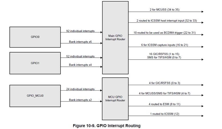
    Please refer below image.

    As per the TRM from the above GPIO interrupt routing diagram, all MCU_GPIO interrupts are routed exclusively to the M4 domain and are not shared with any other cores. In this case, the destination ID would be the same as the source ID. However, if the interrupts are shared with other cores, the destination core must be specified.

    rmIrqReq.dst_id = TISCI_DEV_WKUP_MCU_GPIOMUX_INTROUTER0;

    The next step is to select the Interrupt Router Register from 0 to 12. I selected rmIrqReq.src_index to be 4U. You can any of the GPIO router output among $U, 5U, 6U, & 7U as these are routed to the M4F core. Please refer above diagram.

    rmIrqReq.src_index = 4U;

    Hope the above clarifies.

    Regards,

    Tushar

  • Hi Tushar,

    Thanks for the quick response. So, I now have the interrupt working correctly on pin MCU_GPIO0_7, but not yet on my second pin MCU_GPIO0_14. Both pins are in same bank (CMU BANK_0). The setup in my Sciclient_gpioIrqSet() is this:

        rmIrqReq.src_id                 = TISCI_DEV_WKUP_MCU_GPIOMUX_INTROUTER0;
        rmIrqReq.src_index           = SRC_IDX_BASE_GPIO_BANK;         // (30U)
        rmIrqReq.dst_id                 = TISCI_DEV_WKUP_MCU_GPIOMUX_INTROUTER0;
        rmIrqReq.dst_host_irq       = GPIOMUX_INTROUTER_OUTP;      // (6U)
    So, my src and dst are M4F core. My src_index is (30U), which should be bank interrupt. The above code is called once during Board_init().
    When I register the pin for interrupt, this is my code:

        /* Register pin interrupt */
        HwiP_Params_init(&hwiPrms);
        hwiPrms.intNum = CSLR_MCU_M4FSS0_CORE0_NVIC_WKUP_MCU_GPIOMUX_INTROUTER0_OUTP_6 + 16U;
        hwiPrms.callback = &GPIO_bankIsrFxn;
        hwiPrms.args = (void *)pin;
        result = HwiP_construct(&gGpioHwiObject, &hwiPrms);
    That works well with first pin. When I register the 2nd pin, I call the same code setting up a second gGpioHwiObject structure. Is that correct? If so, should I be using the same value for hwiPrms.intNum for both pins? For the first pin, only CSLR_MCU_M4FSS0_CORE0_NVIC_WKUP_MCU_GPIOMUX_INTROUTER0_OUTP_6 seems to work.
    So, I'm not sure what I'm doing wrong to register the 2nd pin. Also, I'm little confused about the registration of 2nd pin. My understanding of bank interrupt is that the bank interrupt handler will get called for an interrupt on any pin within the bank. Then the interrupt status bitmask from 
    GPIO_getBankIntrStatus() will indicate which pin the interrupt came on. Am I misunderstanding this?
    Thanks again for your patience.
    -Ayman
  • Hi Ayman,

    Are you trying to configure one pin as Bank Interrupt and another pin from the same bank as Pin interrupt?

    Regards,

    Tushar

  • No, just want to configure both pins as bank interrupt and use the intrStatus from GPIO_getBankIntrStatus() to check which pin triggered the interrupt. When I call the code to register the interrupt, I'm using the same callback function for bank interrupt, GPIO_bankIsrFxn(). In that function, I check the intrStatus and then call the appropriate pin interrupt handler.

    I looked at configuring both pins as pin interrupt but looks like you configure the pin interrupt in Sciclient_gpioIrqSet() as the src_index. I can configure src_index with the first pin there, but then that function is only called once during Board_init(). When I call the code to register the pin interrupt, can I call that once for pin1 and a second time for pin2, passing different callbacks? Should different values for hwiPrms.intNum be used?

    -Ayman

  • Hi Ayman,

    In that function, I check the intrStatus and then call the appropriate pin interrupt handler.

    Yes, this is the correct procedure to use bank interrupt. You can have a single interrupt callback and inside that callback you can determine which pin had generated the interrupt and process accordingly.

    When I call the code to register the pin interrupt, can I call that once for pin1 and a second time for pin2

    Yes you can call the functions two time by passing different parameters for configuration. Or you can also configure the two pin interrupt in a single function call like below.

    Please refer below code.

    static void Sciclient_gpioIrqSet(void)
    {
        int32_t                             retVal;
        struct tisci_msg_rm_irq_set_req     rmIrqReq;
        struct tisci_msg_rm_irq_set_resp    rmIrqResp;
        rmIrqReq.valid_params           = 0U;
        rmIrqReq.valid_params          |= TISCI_MSG_VALUE_RM_DST_ID_VALID;
        rmIrqReq.valid_params          |= TISCI_MSG_VALUE_RM_DST_HOST_IRQ_VALID;
        rmIrqReq.global_event           = 0U;
        rmIrqReq.src_id                 = src_id;
        rmIrqReq.src_index              = pin_num1;
        rmIrqReq.dst_id                 = dst_id;
        rmIrqReq.dst_host_irq           = router_num1;
        rmIrqReq.ia_id                  = 0U;
        rmIrqReq.vint                   = 0U;
        rmIrqReq.vint_status_bit_index  = 0U;
        rmIrqReq.secondary_host         = TISCI_MSG_VALUE_RM_UNUSED_SECONDARY_HOST;
    
        retVal = Sciclient_rmIrqSet(&rmIrqReq, &rmIrqResp, SystemP_WAIT_FOREVER);
        if(0 != retVal)
        {
            DebugP_log("[Error] Sciclient event config failed!!!\r\n");
            DebugP_assert(FALSE);
        }
        
        rmIrqReq.valid_params           = 0U;
        rmIrqReq.valid_params          |= TISCI_MSG_VALUE_RM_DST_ID_VALID;
        rmIrqReq.valid_params          |= TISCI_MSG_VALUE_RM_DST_HOST_IRQ_VALID;
        rmIrqReq.global_event           = 0U;
        rmIrqReq.src_id                 = src_id;
        rmIrqReq.src_index              = pin_num2;
        rmIrqReq.dst_id                 = dst_id;
        rmIrqReq.dst_host_irq           = router_num2;
        rmIrqReq.ia_id                  = 0U;
        rmIrqReq.vint                   = 0U;
        rmIrqReq.vint_status_bit_index  = 0U;
        rmIrqReq.secondary_host         = TISCI_MSG_VALUE_RM_UNUSED_SECONDARY_HOST;
    
        retVal = Sciclient_rmIrqSet(&rmIrqReq, &rmIrqResp, SystemP_WAIT_FOREVER);
        if(0 != retVal)
        {
            DebugP_log("[Error] Sciclient event config failed!!!\r\n");
            DebugP_assert(FALSE);
        }
        return;
    }
    

    Should different values for hwiPrms.intNum be used?

    Yes, you will need to use different interrupts number and different router output for each pin interrupt.

    Hope the above helps.

    Regards,

    Tushar