This thread has been locked.

If you have a related question, please click the "Ask a related question" button in the top right corner. The newly created question will be automatically linked to this question.

TDA4VH-Q1: OTP key writer application failure. Debug reponse code -> 65536

Part Number: TDA4VH-Q1

Tool/software:

Hi Team,

  I tried to give below commands to generate keys & build keywriter binary after adding OTP addon into 10.1 PSDK:
          ./gen_keywr_cert.sh -t keys/ti_fek_public.pem -s keys/smpk.pem --smek keys/smek.key
          make keywriter_img BOARD=j784s4_evm

         Debug reponse -> 65536

 
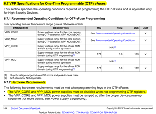
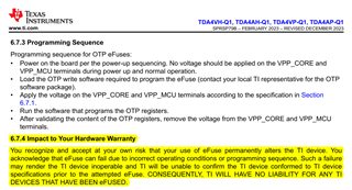
  Found ouput 1V8 is not coming to VPP pins used below reference from TI: [working on why output is not coming as expected]
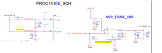
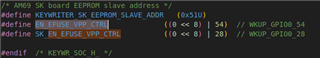
      Using WKUP_GPIO_28 from keywriter application.

  Question: Can we give directly 1.8V to VPP_MCU & VPP_CORE pins?

Thanks,
Sriram

  • Please find below more specific information regarding applying VPP for programming MCU One-Time-Programmable (OTP) eFuses.

    (Note: Programming of CORE OTP eFuses is only done at TI factory during production flow. Customers should only update MCU OTP eFuses. Data manuel updates are pending to add this clarification.)

    MCU OTP Efuse programming guidelines:

    1. Load Switches or Power FETs are not recommended since they do not regulate the voltage therefore any voltage drop of the switch or FET will not be compensated.
    2. TI recommends all customers fully characterize their MCU eFuse VPP supply solution to ensure PCB designs & decoupling caps meet ROC performance shown below before programming any SoCs.
    3. A bench supply interfaced via a board connector could be a valid alternative if ROC performance shown below is met.
    4. A 400mA rated LDO with fast transient response with active pull-down is recommended (i.e. TPS74518P-Q1, TPS7A2118P-Q1).
    5. Sufficient local caps with close PCB placement to achieve small loop inductance are needed to ensure transient currents never cause VPP supply to drop below recommended operational condition (ROC) min of 1.71V (-5%) for any time period during programming.
    6. There may be long-term reliability concerns associated with the eFuse array contents if the VPP voltage is allowed to drop below the ROC limit during programming.
    7. SoC must be in active power state (all supplies enabled for operation).
    8. VPP supply must be under SoC SW GPIO control to implement proper programming sequence.

    For reference, the J784S4 EVM SCH (PROC141E5_SCH) uses WKUP_GPIO_54 in the VDDSHV0_MCU power domain for the EN_EFUSE_VPP control signal to enable the on-board TPS7A2118P-Q1 LDO that supplies VPP_EFUSE_1V8 to VPP_MCU input supply only (VPP_CORE is not connected due to "Do Not Install" in-line resistor isolation).


  • Hey @Bill McCracken

                  Thanks for your detailed response.

                  Can you address few queries on the same topic:

                  1. Can we keep VPP pins to 1.8V pulled high permanently?

                  2. Whether we will have any consequences if we keep VPP pins permanently ON when SoC is turned ON?

                  We were planning to permanently give 1.8V directly to VPP pins without adding any voltage drop regulator.

    Thanks,
    Sriram

  • Hello,

    sorry for jumping in but I have question related to this topic.

    Regarding point no. 4, 400mA LDO rating is required? I'm asking because I've just check EVM schematic and there is 300mA LDO -> TLV73318PQDRVRQ1. Can we use this 300mA LDO from EVM (less expensive by half)?

    Rafał

  • No, VPP pins must not be energized during normal processor operations per DM.

  • The latest J784S4 EVM SCH is vE5 that was released in Sept 2024 and supports the new VPP programming recommendations as highlighted in the SCH Rev History, snap-shot below. The additional drive current is recommended for all J7xxx/TDA4xx SoC based upon the silicon design node for robust eFuse programming to avoid potential negative impacts on SoC as mentioned in the DM, snap-shot below.