Tool/software:
Hi TI Experts,
We refer to TDA4VE EVM (including the SOM, CPB and Fusion Board) as the basis for our custom board design.
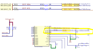
The UB960 serializer is connected to I2C5 of the main domain, consistent with the EVM configuration.

However, we found that I2C5 is currently inaccessible for both read and write operations on our custom board.
To verify this, we performed a simple read/write test on I2C5 by adding the following configuration to the U-Boot device tree.
FILE: u-boot-2021.01+gitAUTOINC+7996ed51f1-g7996ed51f1/arch/arm/dts/k3-j721s2-common-proc-board.dts
main_i2c5_pins_default: main-i2c5-default-pins {
pinctrl-single,pins = <
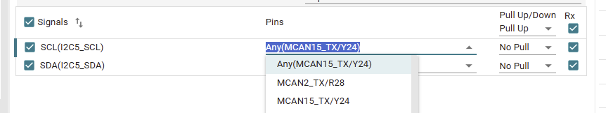
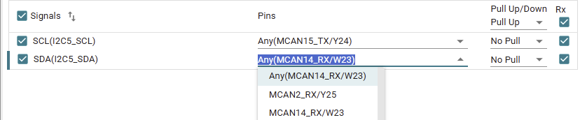
J721S2_IOPAD(0x01c, PIN_INPUT_PULLUP, 8) /* (Y24) MCAN15_TX.I2C5_SCL */
J721S2_IOPAD(0x018, PIN_INPUT_PULLUP, 8) /* (W23) MCAN14_RX.I2C5_SDA */
>;
};
&main_i2c5 {
pinctrl-names = "default";
pinctrl-0 = <&main_i2c5_pins_default>;
clock-frequency = <400000>;
/*clock-frequency = <100000>;*/
status = "okay";
};
On the TDA4EVM EVM, we can successfully communicate with the UB960 over the I2C bus
Please refer to the log below. The pad configurations appear to be correct, the i2c devices on the bus can be successfully scanned, and the registers of UB960 0x3d) is readable.
=> i2c bus
Bus 0:  i2c@42120000
Bus 1:  i2c@40b00000
Bus 2:  i2c@40b10000
Bus 3:  i2c@2000000
   21: gpio@21, offset len 1, flags 0
   20: gpio@20, offset len 1, flags 0
   22: gpio@22, offset len 1, flags 0
Bus 4:  i2c@2010000
Bus 5:  i2c@2030000
Bus 6:  i2c@2040000
   20: gpio@20, offset len 1, flags 0
Bus 7:  i2c@2050000

=> i2c dev 7
Setting bus to 7

=> md.l 0x0011C01C
0011c01c: 00060008 08214007 08214007 08214007    .....@!..@!..@!.
0011c02c: 08214007 08214007 08214007 08214007    .@!..@!..@!..@!.
0011c03c: 08214007 0005000e 0001000e 08214007    .@!..........@!.

=> md.l 0x0011C018
0011c018: 00060008 00060008 08214007 08214007    .........@!..@!.
0011c028: 08214007 08214007 08214007 08214007    .@!..@!..@!..@!.
0011c038: 08214007 08214007 0005000e 0001000e    .@!..@!.........

=> i2c probe
Valid chip addresses: 20 36 3D 50

=> i2c md 0x3d 0x35 1
0035: 00    .
=>
However, the same approach fails when we attempt to access the UB960 on our custom board.
=> i2c bus
Bus 0:  i2c@42120000
Bus 1:  i2c@40b00000
Bus 2:  i2c@40b10000
Bus 3:  i2c@2000000
   21: gpio@21, offset len 1, flags 0
   20: gpio@20, offset len 1, flags 0
   22: gpio@22, offset len 1, flags 0
Bus 4:  i2c@2010000
Bus 5:  i2c@2030000
Bus 6:  i2c@2040000
   20: gpio@20, offset len 1, flags 0
Bus 7:  i2c@2050000

=> i2c dev 7
Setting bus to 7

=> md.l 0x0011C01C
0011c01c: 00060008 08214007 08214007 08214007    .....@!..@!..@!.
0011c02c: 08214007 08214007 08214007 08214007    .@!..@!..@!..@!.
0011c03c: 08214007 0005000e 0001000e 08214007    .@!..........@!.

=> md.l 0x0011C018
0011c018: 00060008 00060008 08214007 08214007    .........@!..@!.
0011c028: 08214007 08214007 08214007 08214007    .@!..@!..@!..@!.
0011c038: 08214007 08214007 0005000e 0001000e    .@!..@!.........

=> i2c probe
Valid chip addresses:Timed out in wait_for_event: status=0000
Check if pads/pull-ups of bus are properly configured
Timed out in wait_for_event: status=0000
Check if pads/pull-ups of bus are properly configured
Timed out in wait_for_event: status=0000
We also attempted a similar access in Linux, but it still failed.
root@j721s2-evm:~# devmem2 0x0011C01C
/dev/mem opened.
Memory mapped at address 0xffff8113f000.
Read at address  0x0011C01C (0xffff8113f01c): 0x40060008
root@j721s2-evm:~# devmem2 0x0011C018
/dev/mem opened.
Memory mapped at address 0xffffaa3da000.
Read at address  0x0011C018 (0xffffaa3da018): 0x00060008
root@j721s2-evm:~#
root@j721s2-evm:~# i2cdetect -l
i2c-3   i2c             OMAP I2C adapter                        I2C adapter
i2c-1   i2c             OMAP I2C adapter                        I2C adapter
i2c-4   i2c             OMAP I2C adapter                        I2C adapter
i2c-2   i2c             OMAP I2C adapter                        I2C adapter
i2c-0   i2c             OMAP I2C adapter                        I2C adapter
root@j721s2-evm:~# i2cdetect -y 4
Warning: Can't use SMBus Quick Write command, will skip some addresses
     0  1  2  3  4  5  6  7  8  9  a  b  c  d  e  f
00:
10:
20:
30: [   72.559377] omap_i2c 2050000.i2c: timeout waiting for bus ready
-- [   73.571375] omap_i2c 2050000.i2c: timeout waiting for bus ready
-- [   74.583373] omap_i2c 2050000.i2c: timeout waiting for bus ready
-- [   75.595376] omap_i2c 2050000.i2c: timeout waiting for bus ready
-- [   76.607375] omap_i2c 2050000.i2c: timeout waiting for bus ready
-- [   77.623373] omap_i2c 2050000.i2c: timeout waiting for bus ready
-- [   78.639375] omap_i2c 2050000.i2c: timeout waiting for bus ready
-- [   79.651374] omap_i2c 2050000.i2c: timeout waiting for bus ready
--
40:
50: [   80.663373] omap_i2c 2050000.i2c: timeout waiting for bus ready
-- [   81.675377] omap_i2c 2050000.i2c: timeout waiting for bus ready
-- [   82.687372] omap_i2c 2050000.i2c: timeout waiting for bus ready
-- [   83.699372] omap_i2c 2050000.i2c: timeout waiting for bus ready
-- [   84.711376] omap_i2c 2050000.i2c: timeout waiting for bus ready
-- [   85.723374] omap_i2c 2050000.i2c: timeout waiting for bus ready
-- [   86.735374] omap_i2c 2050000.i2c: timeout waiting for bus ready
-- [   87.747375] omap_i2c 2050000.i2c: timeout waiting for bus ready
-- [   88.759374] omap_i2c 2050000.i2c: timeout waiting for bus ready
-- [   89.775375] omap_i2c 2050000.i2c: timeout waiting for bus ready
-- [   90.787374] omap_i2c 2050000.i2c: timeout waiting for bus ready
-- [   91.803372] omap_i2c 2050000.i2c: timeout waiting for bus ready
-- [   92.815371] omap_i2c 2050000.i2c: timeout waiting for bus ready
-- [   93.827373] omap_i2c 2050000.i2c: timeout waiting for bus ready
-- [   94.839374] omap_i2c 2050000.i2c: timeout waiting for bus ready
-- [   95.851373] omap_i2c 2050000.i2c: timeout waiting for bus ready
--
60:
70:
root@j721s2-evm:~#
We have no idea why the same software configuration fails on the custom board.
Your guidance would be greatly appreciated, and I look forward to your reply.
Regards,
Christopher