This thread has been locked.

If you have a related question, please click the "Ask a related question" button in the top right corner. The newly created question will be automatically linked to this question.

PROCESSOR-SDK-AM68A: Unable to Read User Button (SW3) State on AM68A SK Board

Part Number: PROCESSOR-SDK-AM68A
Other Parts Discussed in Thread: AM68A, SK-AM68, SYSCONFIG

Tool/software:

Hello TI Team,

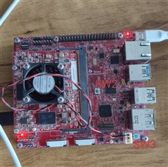
I'm working on the AM68A SK board and trying to read the state of the user button SW3, which I believe is mapped to GPIO line 69 on gpiochip3.

I ran the following command:

gpioget -c /dev/gpiochip3 69

The output is always:

"69"=inactive

This result does not change regardless of whether the button is pressed or not.

Questions:

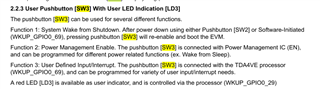
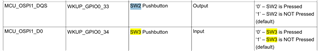
  1. Could you confirm if GPIO3_69 is the correct mapping for SW3 (user button)?

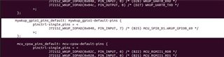
  2. Is there any configuration needed (e.g. muxing, pinctrl, direction, bias) in Linux or device tree to enable reading the button?

  3. Can you provide a method or reference to test SW3 functionality under Linux?

Thanks in advance for your help.


  • Hi,

    Please expect a delay in responses due to US holidays, thank you for your patience!

    Best Regards,
    Sudheer

  • Hi Noushadali,

    Apologies for the delay. I unfortunately do not have a SK-AM68 board, but I have used the pushbutton for other devices and boards. 

    Looking through the dts file for SK-AM68, it looks like there is no entry for WKUP_GPIO0_69. This will need to be added. Can you try following this FAQ which should be applicable to AM68A as well: https://e2e.ti.com/support/processors-group/processors/f/processors-forum/918654/faq-tda4vm-dra829-am65xx-linux-configuring-gpios. Method 1 using sysfs can be ignored (although the methodology to identify which GPIO instance is WKUP_GPIO0 can be used), and method 2 device tree should be followed for making the changes. 

    The changes should be done to the board dts file here: https://git.ti.com/cgit/ti-linux-kernel/ti-linux-kernel/tree/arch/arm64/boot/dts/ti/k3-am68-sk-base-board.dts?h=ti-linux-6.6.y 

    Regards,

    Takuma

  • hi,

    Thanks for the guidance.

    I’ve configured the user button on GPIO69 (WKUP_GPIO0_69) in the device tree using SysConfig, as recommended. The modifications were made in the k3-am68-sk-base-board.dts file.


    However, the GPIO still shows as inactive regardless of button presses. Also, it does not appear under the /sys/class/gpio path.

    Could you please advise if there are any additional steps required to enable this GPIO on the SK-AM68?

    Appreciate your support.


    -Noushad

  • Hi Noushad,

    I looked into this a bit more deeply, did some experiments using a board I borrowed from a colleague, and it seems there are a couple of typos in our schematics and datasheet. 

    Instead of WKUP_GPIO0_69, WKUP_GPIO0_33 is connected to the user pushbutton "SW3" for SK-AM68A. And it looks like no additional pinmuxing is needed in device tree. Please refer to below logs:

    am68a-sk login: root
    [  331.031120] audit: type=1006 audit(1709057363.524:23): pid=1295 uid=0 old-auid=4294967295 auid=0 tty=(none) old-ses=4294967295 ses=3 res=1
    [  331.044031] audit: type=1300 audit(1709057363.524:23): arch=c00000b7 syscall=64 success=yes exit=1 a0=8 a1=ffffe25705c8 a2=1 a3=1 items=0 ppid=1 pid=1295 auid=0 uid=0 gid=0 euid=0 suid=0 fsuid=0 egid=0 sgid=0 fsgid=0 tty=(none) ses=3 comm="(systemd)" exe="/usr/lib/systemd/systemd-executor" key=(null)
    [  331.070725] audit: type=1327 audit(1709057363.524:23): proctitle="(systemd)"
    [  331.090306] audit: type=1334 audit(1709057363.584:24): prog-id=21 op=LOAD
    [  331.097477] audit: type=1300 audit(1709057363.584:24): arch=c00000b7 syscall=280 success=yes exit=8 a0=5 a1=fffff7a0fd58 a2=90 a3=0 items=0 ppid=1 pid=1295 auid=0 uid=0 gid=0 euid=0 suid=0 fsuid=0 egid=0 sgid=0 fsgid=0 tty=(none) ses=3 comm="systemd" exe="/usr/lib/systemd/systemd" key=(null)
    [  331.123703] audit: type=1327 audit(1709057363.584:24): proctitle="(systemd)"
    [  331.131015] audit: type=1334 audit(1709057363.584:25): prog-id=21 op=UNLOAD
    [  331.138352] audit: type=1300 audit(1709057363.584:25): arch=c00000b7 syscall=57 success=yes exit=0 a0=8 a1=1 a2=0 a3=ffff8d10dc60 items=0 ppid=1 pid=1295 auid=0 uid=0 gid=0 euid=0 suid=0 fsuid=0 egid=0 sgid=0 fsgid=0 tty=(none) ses=3 comm="systemd" exe="/usr/lib/systemd/systemd" key=(null)
    [  331.164279] audit: type=1327 audit(1709057363.584:25): proctitle="(systemd)"
    [  331.171664] audit: type=1334 audit(1709057363.584:26): prog-id=22 op=LOAD
    root@am68a-sk:/opt/edgeai-gst-apps# gpioget -c gpiochip3 33
    "33"=active
    root@am68a-sk:/opt/edgeai-gst-apps# gpioget -c gpiochip3 33
    "33"=inactive
    root@am68a-sk:/opt/edgeai-gst-apps# gpioget -c gpiochip3 33
    "33"=inactive
    root@am68a-sk:/opt/edgeai-gst-apps# gpioget -c gpiochip3 33
    "33"=inactive
    root@am68a-sk:/opt/edgeai-gst-apps# gpioget -c gpiochip3 33
    "33"=active
    root@am68a-sk:/opt/edgeai-gst-apps# gpioget -c gpiochip3 33
    "33"=active
    root@am68a-sk:/opt/edgeai-gst-apps# gpioget -c gpiochip3 33
    "33"=active
    root@am68a-sk:/opt/edgeai-gst-apps#
    

    Regards,

    Takuma

  • HI@,

    Thanks for your detailed response and the clarification regarding the pushbutton mapping.

    I tested the behavior on my SK-AM68A board using the command gpioget -c gpiochip3 33 as per your suggestion. However, the output consistently shows "33"=inactive, regardless of whether the SW3 button is pressed or not. Please find the command logs attached below for reference.

    root@am68a-sk:/opt/edgeai-gst-apps# [   44.540298] kauditd_printk_skb: 12 callbacks suppressed
    [   44.540305] audit: type=1334 audit(1748506755.987:30): prog-id=24 op=LOAD
    [   44.556699] audit: type=1334 audit(1748506756.003:31): prog-id=18 op=UNLOAD
    ^C
    root@am68a-sk:/opt/edgeai-gst-apps# gpioget -c gpiochip3 33
    "33"=inactive
    root@am68a-sk:/opt/edgeai-gst-apps# gpioget -c gpiochip3 33
    "33"=inactive
    root@am68a-sk:/opt/edgeai-gst-apps# gpioget -c gpiochip3 33
    "33"=inactive
    root@am68a-sk:/opt/edgeai-gst-apps# gpioget -c gpiochip3 33
    "33"=inactive
    root@am68a-sk:/opt/edgeai-gst-apps# gpioget -c gpiochip3 33
    "33"=inactive
    root@am68a-sk:/opt/edgeai-gst-apps# gpioget -c gpiochip3 33
    "33"=inactive
    root@am68a-sk:/opt/edgeai-gst-apps# gpioget -c gpiochip3 33
    "33"=inactive
    root@am68a-sk:/opt/edgeai-gst-apps# gpioget -c gpiochip3 33
    "33"=inactive
    root@am68a-sk:/opt/edgeai-gst-apps# gpioget -c gpiochip3 33
    "33"=inactive
    root@am68a-sk:/opt/edgeai-gst-apps# gpioget -c gpiochip3 33
    "33"=inactive
    root@am68a-sk:/opt/edgeai-gst-apps#


    Also, based on the SK-AM68A Processor Starter Kit User's Guide, it appears there might be some confusion:

    • SW2 is mapped to GPIO33 and is described as the BOOT switch, so it's not typically used as a user-interactive pushbutton.

    • SW3, which is intended as the user pushbutton, is mapped to GPIO69 and GPIO34.


    I tested both GPIO69 and GPIO34 as well, but they also remain inactive regardless of SW3's state.


    I’ve tested this on two separate AM68A boards, and both show the same results.

    Could you please advise if there’s any additional configuration required (e.g., pinmux, pull-up settings), or if there might be a board revision difference affecting this behavior?

    NOUSHAD

  • Hi Noushad,

    I understand the user guide and schematics say SW2 is mapped to WKUP_GPIO33 instead of SW3. However, I reviewed the schematics and I found SW3 labeled as USER PB looks to be connected to SOC_WAKE, which is WKUP_GPIO33 instead of 69. 

    I think the user guide has these switched, because I was able to use SW3 for WKUP_GPIO33 as shown in logs. Additionally, as an experiment, I toggled WKUP_GPIO69 through gpioset and this caused a reset to happen, which makes me believe WKUP_GPIO69 is connected to SW2 labeled as PORZ (Power On Reset).

    As an experiment, before reading/writing to the GPIO pin values, you could try to read and write to the PADCONFIG registers that the dts file should be setting using devmem2. Specific commands are:

    • To read PADCONFIG of WKUP_GPIO0_33: "devmem2 0x4301C048"
    • To set RXACTIVE bits and pinmux as 7 (GPIO): "devmem2 0x4301C048 w 0x50007"
    • To read PADCONFIG of WKUP_GPIO0_69: "devmem2 0x4301C0A8"
    • To set RXACTIVE bits and pinmux as 7 (GPIO): "devmem2 0x4301C0A8 w 0x50007"

    This should let you read/write the value of the GPIO pins using gpioget/gpioset. 

    Regards,

    Takuma

  • Hi ,

    Thank you for your valueable support now i can use sw3 as user interrupt button
    like can i set GPIO as output mode? then set active high and low?

    -Noushad

  • Hi Noushad,

    Glad you were able to get the button functional!

    Output and input are controlled by different independent bits and internal circuitry. By default, TX_DIS bit is unset, enabling output. So, you should be able to set the value as high and low using gpioset if the padconfig registers are written with the values in my previous response.

    As a sidenote, devmem2 is directly programming the padconfig registers, and good for troubleshooting, but dts should be the proper way to program the padconfig registers.

    Regards,

    Takuma