This thread has been locked.

If you have a related question, please click the "Ask a related question" button in the top right corner. The newly created question will be automatically linked to this question.

AM2432: OSPI DDR input data sampling timing

Part Number: AM2432

Tool/software:

Hi,

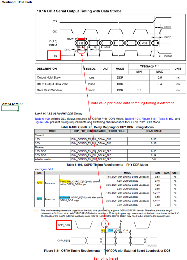
Customer is asking the sampling timing of input data for OSPI DDR mode.

Can you see the figure as below? 

For Winbond OSPI Flash (W35T25NW) , data valid period is when DQS is flat.

On the other hand, for AM2432, data sampling timing looks like at the edge of DQS.  

  1. Is it possible to communicate between these 2 device?
  2.  Is there any way to change sampling timing for AM2432?

Best Regards,

Kasai

  • Hello Kasai

    Thank you for the query.

    Let me assign the query to the expert to support.

    Regards,

    Sreenivasa

  • Hi Sreenivasa,

    Thank you for your support.

    Did you get any feedback?

    Best Regards,
    Kasai

  • Hi Sreenivasa,

    Is my understanding below correct?

    Since the required setup time by AM2432 is minus,  so it is ok that data becomes valid after the sampling edge. 

    As the picture below shows, it looks OSPI Flash output valid period is within the period between setup and hold required by AM2432.  

    I also found the application note as below. If above is not true, should we use this? I'm not so sure how it works. 

    www.ti.com/.../spract2.pdf

    Best Regards,

    Kasai

  • Greetings Kasai,

    Please be aware of errata item i2383 "OSPI: 2-byte address is not supported in PHY DDR mode". The W35 is a NAND flash that uses 2 byte addressing for it's read data commands (it only has to address a page instead of the full memory), so it would not be compatible in DDR mode. The customer should use SDR mode to communicate with this flash device.

    It's possible to use the W35 flash, it's been used on other devices that share the same controller (like https://www.ti.com/tool/SK-AM62A-LP ) for example. Recommend to use the SDK training software for data training to establish high speed communication.

    Sincerely,

    Lucas

  • Hi Lucaas,

    Thank you for your reply.

    Regarding my previous question, is my understanding of set-up time and hold time correct?

    Especially I want to know the meaning of minus of setup time. Usually setup time is before the strobe point. However, in the case of minus setup time, is it after the strobe point? Is there any internal delayed strobe point?

    Best Regards,

    Kasai

  • Greetings Kasai,

    Your understanding of negative setup time is correct, it would be to the right of the strobe as in the diagram. If you'll notice as well that whenever setup is negative, hold will always be positive.

    Speaking generally, it's also technically possible to have a negative hold time, in which case the setup time will always be positive. The only scenario that will never happen is negative setup and negative hold.

    Sincerely,

    Lucas

  • Hi Lucas,

    Thank you for your reply.

    I understood.

    Best Regards,

    Kasai