Other Parts Discussed in Thread: DRA821
Tool/software:
Hi Team,
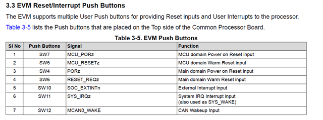
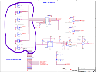
Please explain all switch's (SW4, SW5, SW6, SW78, SW10, SW11, application in details in attached images, can we customize some switches if it not necessary too much.
Regards,
Jitendra
Original question: