This thread has been locked.

If you have a related question, please click the "Ask a related question" button in the top right corner. The newly created question will be automatically linked to this question.

J721EXSOMXEVM: Transmitting data over SPI3 and SPI6 only transmits one byte

Part Number: J721EXSOMXEVM

Tool/software:

I've moved on to a full J721E board with the SOM from a TVA4VM board, now accessing MCSPI3 and MCSPI6 through the GESI board. I'm using MCU2_1, FreeRTOS, using the 10.x TI SDK w/ PDK.

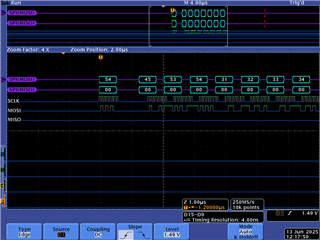
I've observed I can successfully transmit and receive on each, but in every case I've tried, I'm only transmitting one byte. I would expect there to be the entire message. 

Task launched:

void spi_test_master_cb(void *arg0, void *arg1)
{
    UART_printf("Starting SPI Master test. \n");
    TaskP_sleepInMsecs(1000);
    uint32_t  terminateXfer = 1;

    SPI_init();

    // == Set up the SPI test for receive ==
    SPI_Handle        spi;
    SPI_Params        spiParams;

    // Creates a callback semaphore
    SPI_osalSemParamsInit(&cbSemParams);
    cbSemParams.mode = SemaphoreP_Mode_BINARY;
    cbSem[0] = SPI_osalCreateBlockingLock(0, &cbSemParams);

    uint32_t instance = MCSPI3_CONFIG_IDX; 
    uint32_t domain = SPI_MCSPI_DOMAIN_MAIN;

    // MCSPI_socInit();

    SPI_HWAttrs spi_cfg;
    SPI_socGetInitCfg(domain, instance, &spi_cfg);
    spi_cfg.enableIntr = BFALSE; 
    spi_cfg.edmaHandle = NULL;
    spi_cfg.dmaMode    = BFALSE;

    /* Set the SPI init configurations */
    spi_cfg.chNum = 0;
    spi_cfg.chnCfg[0].dataLineCommMode = MCSPI_DATA_LINE_COMM_MODE_6;
    spi_cfg.chnCfg[0].tcs = MCSPI_CS_TCS_0PNT5_CLK;
    spi_cfg.chnCfg[0].trMode = MCSPI_TX_ONLY_MODE;

    /* Set the SPI init configurations */
    SPI_socSetInitCfg(domain, instance, &spi_cfg);

    /* Initialize SPI handle */
    SPI_Params_init(&spiParams);
    spiParams.mode = SPI_MASTER;
    spiParams.transferMode = SPI_MODE_BLOCKING;
    spiParams.transferTimeout = SemaphoreP_WAIT_FOREVER;
    spiParams.frameFormat = SPI_POL1_PHA0;
    spiParams.dataSize = 8U; // 8 bits
    spiParams.bitRate = 468750;

    spi = SPI_open(domain, instance, &spiParams);

    if (NULL == spi)
    {
        UART_printf("Error initializing SPI\n");
        return;
    }

    uint32_t num_xfers = 0;
    uint32_t xfer_len = SPI_MSG_LENGTH; //8

    Osal_delay(500);

    // Attempt a transfer
    // uintptr_t addrMasterRxBuf = (uintptr_t)masterRxBuffer;
    uintptr_t addrMasterTxBuf = (uintptr_t)masterTxBuffer;
    bool transferOK = true;

    // memset(masterRxBuffer, 0, sizeof(masterRxBuffer));
    memset(masterTxBuffer, 0, sizeof(masterTxBuffer));

    while (1)
    {

        memcpy(masterTxBuffer, "TEST1234", 8);

        SPI_Transaction   transaction;
        transaction.count = xfer_len;
        transaction.arg = (void *)&terminateXfer;
        transaction.txBuf = (void *)addrMasterTxBuf;
        transaction.rxBuf = NULL; // (void *)addrMasterRxBuf;
        
        transferOK = SPI_transfer((SPI_Handle)spi, &transaction);
        if (!transferOK)
        {
            UART_printf("Error in SPI transfer\n");
        }
        else
        {   
            UART_printf("SPI transfer successful.\n");

        }
        Osal_delay(10);

    }
}

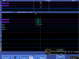
I've discovered if I enable TURBO mode, I get two bytes, but I never get the whole message. Also if I change 'dataSize' in the SPI_Params struct, it does seem to scale to two bytes, but it's impractical for larger messages.

Other things I've tinkered with but didn't see a change/couldn't get working:

* Increasing the bitrate.

* Adjusting the txTrigLvl in the SPI_HWAttrs.

Any ideas what else I should try, or do you see a setting here that isn't correct?

  • Hello,

    Are you using custom SPI driver ? on which SDK as well 10.0 or 10.1 ?

    I see only MCSPI_TX_ONLY_MODE being used for SPI6 .Can you please explain your use case more clearly ? Is SPI3 sending data to SPI6 here or vice versa ?

    Regards

    Tarun Mukesh

  • Are you using custom SPI driver ? on which SDK as well 10.0 or 10.1 ?

    I'm using the SPI driver from the PDK. SDK version is 10.01.00.04 with PDK 10.01.00.25.

    I see only MCSPI_TX_ONLY_MODE being used for SPI6 .Can you please explain your use case more clearly ? Is SPI3 sending data to SPI6 here or vice versa ?

    I currently have SPI3 directly connected to the oscilloscope. Nothing is being done to SPI6 at the moment.

    The only reason I'm including SPI6 here is to show that this isn't only happening to SPI3. I'd likely be able to demonstrate this with other SPIs if I can access them easily. In either case, I'm only using one SPI, whether it be 3 or 6, connected to the oscilloscope.

  • As an experiment, I've tried the same code (except changed it to SPI5) and ran it on the TVA4VM board. I'm seeing 3 bytes come through. It's still not the entire 8 bytes I'm expecting, but it's different.

    This is weird. I know before when I've done tests with send and receive with the board as a slave, I'm getting the entire messages, but when I'm just doing a TX only, it's not sending the entire message. There must be something I'm missing here to understand. Surely not every TI product is faulty.

    Edit: Again, experimenting. Changed from MCU2_1 to MCU2_0 on the TVA4VM, and I'm back at one byte. Something is terminating the transfer early.

    Edit2: I changed the bitrate to be 12 MHz. I'm seeing the full message, and it seems it's hinting at what is happening:

    A large gap is between the first byte and the rest. No idea what is delaying it, but at lower bit rates, that gap is where it gets cut off. And yes, at the lower bit rate, the rest of the message is definitely not transmitted. I've verified this by eliminating the `Osal_delay(10);` and seeing that it's just repeating the one byte over and over.

    Do understand that a higher bit rate is not the solution here.

  • So disabling the FIFO (.enableFIFO = 0) in the SPI_HWAttrs seems to allow the full expected data through, so the problem seems to be FIFO related. The question now is how come?

    Looking under the hood, I'm seeing that in SPI_v1.c in the PDK is using the full MCSPI_FULL_FIFO_SIZE for the FIFO size and then overrides the txTrigLvl in MCSPI_xferSetup_v1() to the size of the data (or the transaction->count). So far it seems like that's how it should go.

  • As an experiment, I've tried the same code (except changed it to SPI5) and ran it on the TVA4VM board. I'm seeing 3 bytes come through. It's still not the entire 8 bytes I'm expecting, but it's different.

    This is weird. I know before when I've done tests with send and receive with the board as a slave, I'm getting the entire messages, but when I'm just doing a TX only, it's not sending the entire message. There must be something I'm missing here to understand. Surely not every TI product is faulty.

    Edit: Again, experimenting. Changed from MCU2_1 to MCU2_0 on the TVA4VM, and I'm back at one byte. Something is terminating the transfer early.

    By changing cores and SPI instances the driver will not behave differently. I expect the issue is elsewhere.

    How many bytes are you transferring in a message ? and also are you using SPI with DMA ? if so then your message should be in multiple of trglvl.

    Regards

    Tarun Mukesh

  • How many bytes are you transferring in a message ?

    8 bytes in this message, but I plan on doing more in the future.

    and also are you using SPI with DMA ?

    No DMA.

  • Hello Tyler,

    If you are not using DMA then there shouldn't be any problem at all with FIFO.

    It is highly unclear for me based on your comments what could be the issue ?

    For Tx and Rx mode you are able to see full message but facing below issues for Tx only mode

    1) SPI3  you are only able to transfer 1 byte out of 8 bytes on MCU2_1, enabling turbo mode transfers 2 bytes out of 8.

    2) SPI5 you are able to transfer 3 bytes out of 8 bytes on MCU2_1

    3) SPI5 again you are able to transfer only 1 byte of 8 bytes on MCU2_0

    4) You changed bit rate to 12 MHz then able to see full message but gap between first message byte and the later ones.

    5) If FIFO disabled then full message without any gap.

     It would be good if you take one scenario SPI3 on MCU2_1 and share me the core register dump for analysis.

    Looking under the hood, I'm seeing that in SPI_v1.c in the PDK is using the full MCSPI_FULL_FIFO_SIZE for the FIFO size and then overrides the txTrigLvl in MCSPI_xferSetup_v1() to the size of the data (or the transaction->count). So far it seems like that's how it should go.

    If the transaction message bytes are less than the FIFO_FULL_SIZE for Tx only mode then the trigger level will be updated based on transaction bytes in your case which is 8. That should be ok since then only the trigger will occur to send the bytes for transfer.

    Is there any parallel access of these instances from other cores ? if not i don't see why these many failure conditions are occurring.  

    One check is SPI3 is by default connected as slave to MCU_SPI1

    You can refer https://e2e.ti.com/support/processors-group/processors/f/processors-forum/1128170/tda4vm-internal-spi-communication-between-spi3-and-spi6-not-working

    Regards

    Tarun Mukesh

  • For Tx and Rx mode you are able to see full message but facing below issues for Tx only mode

    I haven't brought anything about Rx mode into this yet. Having issues with it, but that's a whole different topic.

    Is there any parallel access of these instances from other cores ?

    No. mcu1_0 is running the SciServer, and I'm only running code on mcu2_1.

    One check is SPI3 is by default connected as slave to MCU_SPI1

    I think I can force it with 

    CSL_REG32_WR(CSL_MCU_CTRL_MMR0_CFG0_BASE +
        CSL_MCU_CTRL_MMR_CFG0_MCU_SPI1_CTRL,
            CSL_MCU_CTRL_MMR_CFG0_MCU_SPI1_CTRL_SPI1_LINKDIS_MASK);
    

    But doing that is ineffective.

    I went back to the original situation above with SPI3 and got a core register dump, though no idea how this may help:

    521177 13
    R PC 0x0000000B 0x800346FC
    R SP 0x0000000B 0x80019670
    R LR 0x0000000B 0x800302BD
    R CPSR 0x0000000B 0x6000001F
    R R0 0x0000000B 0x00000000
    R R1 0x0000000B 0x800456FC
    R R2 0x0000000B 0x000001B9
    R R3 0x0000000B 0x00000000
    R R4 0x0000000B 0x800456E4
    R R5 0x0000000B 0x05050505
    R R6 0x0000000B 0x800456E8
    R R7 0x0000000B 0x8001BECC
    R R8 0x0000000B 0x8001B7E0
    R R9 0x0000000B 0x8004E554
    R R10 0x0000000B 0x10101010
    R R11 0x0000000B 0x11111111
    R R12 0x0000000B 0x00000000
    R R13 0x0000000B 0x80019670
    R R14 0x0000000B 0x800302BD
    

    I have discovered that if I put the transferMode in SPI_MODE_CALLBACK, that it functions as I want it. It seems strange that having it in blocking mode is malformatting the output.

  • So the above where I'm attempting to set the SPI1_LINKDIS flag, but it seems like it's still not being set. I added breakpoints before and after, and not seeing the value change.

    This isn't making any sense. I can see clearly that the memory address is 0x40F04060, and any code I do to write to it just isn't working.

  • Hello,

    I think I can force it with 

    So the above where I'm attempting to set the SPI1_LINKDIS flag, but it seems like it's still not being set. I added breakpoints before and after, and not seeing the value change.

    This isn't making any sense. I can see clearly that the memory address is 0x40F04060, and any code I do to write to it just isn't working.

    This is an MMR register , you cannot directly write without unlocking the MMR registers with keys .

    You need to do as below,

    FIrst unlock the MMR partition where the register lies in with key and then write into the register. 

        /* Unlock lock key registers for Partition 1 */
        /* write Partition Lock Key 0 Register */
        CSL_REG32_WR(CSL_MCU_CTRL_MMR0_CFG0_BASE + CSL_MCU_CTRL_MMR_CFG0_LOCK1_KICK0, 0x68EF3490);
        /* write Partition Lock Key 1 Register */
        CSL_REG32_WR(CSL_MCU_CTRL_MMR0_CFG0_BASE + CSL_MCU_CTRL_MMR_CFG0_LOCK1_KICK1, 0xD172BC5A);
        /* Check for unlock */
        regVal = CSL_REG32_RD(CSL_MCU_CTRL_MMR0_CFG0_BASE + CSL_MCU_CTRL_MMR_CFG0_LOCK1_KICK0);
        while ((regVal & 0x1) != 0x1U)
        {
            regVal = CSL_REG32_RD(CSL_MCU_CTRL_MMR0_CFG0_BASE + CSL_MCU_CTRL_MMR_CFG0_LOCK1_KICK0);
        }
    
        /* Enable MCU_MCSPI1 and MCSPI3 independently pin out */
        CSL_REG32_WR(CSL_MCU_CTRL_MMR0_CFG0_BASE + CSL_MCU_CTRL_MMR_CFG0_MCU_SPI1_CTRL, CSL_MCU_CTRL_MMR_CFG0_MCU_SPI1_CTRL_SPI1_LINKDIS_MASK);
    

    I went back to the original situation above with SPI3 and got a core register dump, though no idea how this may help:

    you are sharing the R1 to R14 registers, these are not helpful. I need core registers of SPI please see the below screenshot

    Regards

    Tarun Mukesh

  • and also

    I have discovered that if I put the transferMode in SPI_MODE_CALLBACK, that it functions as I want it. It seems strange that having it in blocking mode is malformatting the output.

    Are you saying everything works fine for SPI_MODE_CALLBACK as expected on SPI3 ?if so then above configurations would be correct only .

    Regards

    Tarun Mukesh

  • FIrst unlock the MMR partition where the register lies in with key and then write into the register. 

    Got it! I'm seeing that happen now. No changes there.

    you are sharing the R1 to R14 registers, these are not helpful. I need core registers of SPI

    Ah, sorry for the confusion. This should be it:

    521177 13
    R MCSPI3_CFG_MCSPI_HL_REV 0x0000000B 0x40301A0B
    R MCSPI3_CFG_MCSPI_HL_HWINFO 0x0000000B 0x00000009
    R MCSPI3_CFG_MCSPI_HL_SYSCONFIG 0x0000000B 0x00000004
    R MCSPI3_CFG_MCSPI_REVISION 0x0000000B 0x0000002B
    R MCSPI3_CFG_MCSPI_SYSCONFIG 0x0000000B 0x00000308
    R MCSPI3_CFG_MCSPI_SYSSTATUS 0x0000000B 0x00000001
    R MCSPI3_CFG_MCSPI_IRQSTATUS 0x0000000B 0x00000001
    R MCSPI3_CFG_MCSPI_IRQENABLE 0x0000000B 0x00000000
    R MCSPI3_CFG_MCSPI_WAKEUPENABLE 0x0000000B 0x00000000
    R MCSPI3_CFG_MCSPI_SYST 0x0000000B 0x00000000
    R MCSPI3_CFG_MCSPI_MODULCTRL 0x0000000B 0x00000001
    R MCSPI3_CFG_MCSPI_CHCONF_0 0x0000000B 0x280623D0
    R MCSPI3_CFG_MCSPI_CHSTAT_0 0x0000000B 0x00000006
    R MCSPI3_CFG_MCSPI_CHCTRL_0 0x0000000B 0x00001401
    R MCSPI3_CFG_MCSPI_TX_0 0x0000000B 0x00000034
    R MCSPI3_CFG_MCSPI_RX_0 0x0000000B 0x00000000
    R MCSPI3_CFG_MCSPI_CHCONF_1 0x0000000B 0x00060000
    R MCSPI3_CFG_MCSPI_CHSTAT_1 0x0000000B 0x00000000
    R MCSPI3_CFG_MCSPI_CHCTRL_1 0x0000000B 0x00000000
    R MCSPI3_CFG_MCSPI_TX_1 0x0000000B 0x00000000
    R MCSPI3_CFG_MCSPI_RX_1 0x0000000B 0x00000000
    R MCSPI3_CFG_MCSPI_CHCONF_2 0x0000000B 0x00060000
    R MCSPI3_CFG_MCSPI_CHSTAT_2 0x0000000B 0x00000000
    R MCSPI3_CFG_MCSPI_CHCTRL_2 0x0000000B 0x00000000
    R MCSPI3_CFG_MCSPI_TX_2 0x0000000B 0x00000000
    R MCSPI3_CFG_MCSPI_RX_2 0x0000000B 0x00000000
    R MCSPI3_CFG_MCSPI_CHCONF_3 0x0000000B 0x00060000
    R MCSPI3_CFG_MCSPI_CHSTAT_3 0x0000000B 0x00000000
    R MCSPI3_CFG_MCSPI_CHCTRL_3 0x0000000B 0x00000000
    R MCSPI3_CFG_MCSPI_TX_3 0x0000000B 0x00000000
    R MCSPI3_CFG_MCSPI_RX_3 0x0000000B 0x00000000
    R MCSPI3_CFG_MCSPI_XFERLEVEL 0x0000000B 0x00070007
    R MCSPI3_CFG_MCSPI_DAFTX 0x0000000B 0x00000000
    R MCSPI3_CFG_MCSPI_DAFRX 0x0000000B 0x00000000
    

    And I isolated the code so I can share the entirety of it with you.

    #include <stdio.h>
    #include <string.h>
    #include <ti/osal/osal.h>
    #include <ti/drv/sciclient/sciclient.h>
    
    /* TI-RTOS Header files */
    #include <ti/drv/spi/soc/SPI_soc.h>
    #include <ti/drv/spi/src/SPI_osal.h>
    #include <ti/drv/spi/SPI.h>
    
    #include <ti/board/src/j721e_evm/include/board_utils.h>
    #include <ti/csl/soc/j721e/src/cslr_soc_baseaddress.h>
    #include <ti/csl/soc/j721e/src/cslr_wkup_ctrl_mmr.h>
    
    
    /** \brief Application stack size */
    #define APP_TSK_STACK_MAIN              (0x4000U)
    /** \brief Task stack */
    static uint8_t  gAppTskStackMain[APP_TSK_STACK_MAIN] __attribute__((aligned(32)));
    
    /* Maximum # of channels per SPI instance */
    #define MCSPI_MAX_NUM_CHN       4
    
    /* SPI transfer message definitions */
    #define SPI_MSG_LENGTH    8
    #define SPI_WORD_SIZE_IN_BITS 8
    
    #define SIZE_TOO_LARGE          (0x1FFFU)
    
    #define MCSPI3_CONFIG_IDX       (3U)
    #define MCSPI6_CONFIG_IDX       (6U)
    
    #ifdef __cplusplus
    extern "C" {
    #endif //__cplusplus
    
    extern void UART_printf(const char *pcString, ...);
    
    #ifdef __cplusplus
    }
    #endif //__cplusplus
    
    /* Callback mode variables */
    SemaphoreP_Params cbSemParams;
    SemaphoreP_Handle cbSem[MCSPI_MAX_NUM_CHN] = {NULL, NULL, NULL, NULL};
    
    unsigned char masterRxBuffer[128] __attribute__ ((aligned (128)));
    unsigned char masterTxBuffer[128] __attribute__ ((aligned (128)));
    
    void MCSPI_initSciclient()
    {
        int32_t ret = CSL_PASS;
        Sciclient_ConfigPrms_t        config;
    
        /* Now reinitialize it as default parameter */
        ret = Sciclient_configPrmsInit(&config);
        if (CSL_PASS != ret)
        {
            UART_printf("Sciclient_configPrmsInit Failed\n");
        }
        else if (CSL_PASS == ret)
        {
            ret = Sciclient_init(&config);
            if (CSL_PASS != ret)
            {
                UART_printf("Sciclient_init Failed\n");
            }
        }
    }
    
    /* Callback mode functions */
    // NOT CURRENTLY USED
    void SPI_callback(SPI_Handle handle, SPI_Transaction *transaction)
    {
        UART_printf("SPI callback data size: %d\n", transaction->count);
        if (transaction->count > SIZE_TOO_LARGE)
        {
            SemaphoreP_post(cbSem[0]);
            return;
        }
    
        // uint8_t numToCopy = transaction->count * (SPI_WORD_SIZE_IN_BITS / 8);
        // CircularBuffer_write(&g_rxbuffer, reinterpret_cast<uint8_t*>(transaction->rxBuf), numToCopy);
        SemaphoreP_post(cbSem[0]);
    }
    
    void spi_test_master(void *arg0, void *arg1)
    {
        UART_printf("Starting SPI Master test. \n");
        TaskP_sleepInMsecs(1000);
        uint32_t  terminateXfer = 1;
    
        SPI_init();
    
        // == Set up the SPI test for receive ==
        SPI_Handle        spi;
        SPI_Params        spiParams;
        // Note: master is false, pollmode is false, cbmode is true, timeout should be SemaphoreP_WAIT_FOREVER
    
        // Creates a callback semaphore
        SPI_osalSemParamsInit(&cbSemParams);
        cbSemParams.mode = SemaphoreP_Mode_BINARY;
        cbSem[0] = SPI_osalCreateBlockingLock(0, &cbSemParams);
    
        uint32_t instance = MCSPI3_CONFIG_IDX; //SPI_test_get_instance(2, false);
        uint32_t domain = SPI_MCSPI_DOMAIN_MAIN; //SPI_test_get_domain(2, false);
    
        // SPI_initConfig(domain, instance, test, MCSPI_TEST_CHN, BFALSE); --> expanded below
        MCSPI_socInit();
    
        SPI_HWAttrs spi_cfg;
        SPI_socGetInitCfg(domain, instance, &spi_cfg);
        spi_cfg.enableIntr = BFALSE; // BTRUE;
        spi_cfg.edmaHandle = NULL;
        spi_cfg.dmaMode    = BFALSE;
    
        /* Set the SPI init configurations */
        spi_cfg.chNum = 0;
        spi_cfg.chnCfg[0].dataLineCommMode = MCSPI_DATA_LINE_COMM_MODE_6;
        spi_cfg.chnCfg[0].tcs = MCSPI_CS_TCS_0PNT5_CLK;
        spi_cfg.chnCfg[0].trMode = MCSPI_TX_ONLY_MODE;
    
    
        /* Set interrupt path */
        if(CSL_PASS != MCSPI_configSocIntrPath(instance, &spi_cfg, BTRUE))
        {
            UART_printf("\n Set interrupt path failed! Interrupt number %d\n", spi_cfg.intNum);
        }
        else
        {
            UART_printf("\n The interrupt path has been set with interrupt number %d\n", spi_cfg.intNum);
        }
    
        /* Set the SPI init configurations */
        SPI_socSetInitCfg(domain, instance, &spi_cfg);
    
        /* Initialize SPI handle */
        SPI_Params_init(&spiParams);
        spiParams.mode = SPI_MASTER;
        spiParams.transferMode = SPI_MODE_BLOCKING; // SPI_MODE_CALLBACK;
        // spiParams.transferCallbackFxn = SPI_callback;
        spiParams.transferTimeout = SemaphoreP_WAIT_FOREVER;
        spiParams.frameFormat = SPI_POL1_PHA0;
        spiParams.dataSize = 8U; // 8 bits
        spiParams.bitRate = 153600; // 153.6kHz
    
        spi = SPI_open(domain, instance, &spiParams);
    
        if (NULL == spi)
        {
            UART_printf("Error initializing SPI\n");
            return;
        }
    
        uint32_t xfer_len = SPI_MSG_LENGTH;
    
        Osal_delay(500);
    
        // Attempt a transfer
        uintptr_t addrMasterTxBuf = (uintptr_t)masterTxBuffer;
        bool transferOK = true;
    
        memset(masterRxBuffer, 0, sizeof(masterRxBuffer));
        memset(masterTxBuffer, 0, sizeof(masterTxBuffer));
    
        memcpy(masterTxBuffer, "TEST1234", 8);
        
        while (1)
        {
            SPI_Transaction   transaction;
            transaction.count = xfer_len;
            transaction.arg = (void *)&terminateXfer;
            transaction.txBuf = (void *)addrMasterTxBuf;
            transaction.rxBuf = NULL;
    
            transferOK = SPI_transfer((SPI_Handle)spi, &transaction);
            if (!transferOK)
            {
                UART_printf("Error in SPI transfer\n");
            }
            else
            {   
                UART_printf("SPI transfer successful.\n");
            }
            Osal_delay(1000);
        }
    }
    
    /*
     *  ======== main ========
     */
     int main(void)
     {
        UART_printf("[UART] spi_test main()\n");
    
        /*  This should be called before any other OS calls (like Task creation, OS_start, etc..) */
        OS_init();
    
        /* Call board init functions */
        Board_initCfg boardCfg;
        Board_STATUS  boardStatus;
    
        /* Initialize the task params */
        TaskP_Params taskParams;
        TaskP_Params_init(&taskParams);
    
        /* Set the task priority higher than the default priority (1) */
        taskParams.priority     = 2;
        taskParams.stack        = gAppTskStackMain;
        taskParams.stacksize    = sizeof (gAppTskStackMain);
    
        TaskP_Params taskDataProcess;
        TaskP_Params_init(&taskDataProcess);
        
        TaskP_create(&spi_test_master, &taskParams);
    
        // If we run on MCU1_0, we need to setup the SciServer
        // For now, we will set up for MCU2_0, which uses a sciclient
        MCSPI_initSciclient();
    
        Board_PinmuxConfig_t boardPinmuxCfg;
        Board_pinmuxGetCfg(&boardPinmuxCfg);
        // boardPinmuxCfg.autoCfg = BOARD_PINMUX_AUTO;
        boardPinmuxCfg.gesiExp = BOARD_PINMUX_GESI_ICSSG;
        Board_pinmuxSetCfg(&boardPinmuxCfg);
    
        boardCfg = BOARD_INIT_PINMUX_CONFIG |
                   BOARD_INIT_MODULE_CLOCK  |
                   BOARD_INIT_UART_STDIO |
                   BOARD_INIT_MODULE_CLOCK_MAIN;
        boardStatus = Board_init(boardCfg);
    
        /* Unlock lock key registers for Partition 1 */
        /* write Partition Lock Key 0 Register */
        CSL_REG32_WR(CSL_MCU_CTRL_MMR0_CFG0_BASE + CSL_MCU_CTRL_MMR_CFG0_LOCK1_KICK0, 0x68EF3490);
        /* write Partition Lock Key 1 Register */
        CSL_REG32_WR(CSL_MCU_CTRL_MMR0_CFG0_BASE + CSL_MCU_CTRL_MMR_CFG0_LOCK1_KICK1, 0xD172BC5A);
        /* Check for unlock */
        uint32_t regVal = CSL_REG32_RD(CSL_MCU_CTRL_MMR0_CFG0_BASE + CSL_MCU_CTRL_MMR_CFG0_LOCK1_KICK0);
        while ((regVal & 0x1) != 0x1U)
        {
            regVal = CSL_REG32_RD(CSL_MCU_CTRL_MMR0_CFG0_BASE + CSL_MCU_CTRL_MMR_CFG0_LOCK1_KICK0);
        }
    
        /* Enable MCU_MCSPI1 and MCSPI3 independently pin out */
        CSL_REG32_WR(CSL_MCU_CTRL_MMR0_CFG0_BASE +
            CSL_MCU_CTRL_MMR_CFG0_MCU_SPI1_CTRL,
                CSL_MCU_CTRL_MMR_CFG0_MCU_SPI1_CTRL_SPI1_LINKDIS_MASK);
    //    *((uint32_t*)(0x40F04060)) = 1;
    
        // Creates a callback semaphore
        SemaphoreP_Params_init(&cbSemParams);
        cbSemParams.mode = SemaphoreP_Mode_BINARY;
        cbSem[0] = SemaphoreP_create(0, &cbSemParams);
    
        /* Start the scheduler to start the tasks executing. */
        OS_start();
     }

    cmake_minimum_required(VERSION 3.24)
    
    # Set the project name and version
    project(spitx VERSION 1.0)
    
    # Use debug or release libs
    if(CMAKE_BUILD_TYPE STREQUAL "Release")
        set(BUILD_PROFILE "release")
    else()
        set(BUILD_PROFILE "debug")
    endif()
    
    if(NOT DEFINED BOARD)
        set(BOARD "j721e_evm")
    endif()
    
    # Set the target processor
    if(NOT DEFINED TARGET_PROCESSOR)
        set(TARGET_PROCESSOR "r5f")  # Modify this according to your target processor (R5F or A72, etc.)
    elseif(NOT "${TARGET_PROCESSOR}" STREQUAL "r5f")
        message(FATAL_ERROR "TARGET_PROCESSOR=${TARGET_PROCESSOR} is not supported for this project.")
    endif()
    
    # Set the target core
    # mcu1_0 mcu1_1 are no longer supported
    set(SUPPORTED_CORES mcu2_0 mcu2_1)
    if(NOT DEFINED TARGET_CORE)
        set(TARGET_CORE "mcu2_1")
    elseif(NOT "${TARGET_CORE}" IN_LIST SUPPORTED_CORES)
        message(FATAL_ERROR "TARGET_CORE=${TARGET_CORE} not in supported core list.")
    endif()
    
    # Append to additional build options
    if("${TARGET_CORE}" STREQUAL "mcu2_0")
        set(ADDITIONAL_BUILD_OPTS "${ADDITIONAL_BUILD_OPTS} -DBUILD_MCU2_0 -DBUILD_MCU")
    elseif("${TARGET_CORE}" STREQUAL "mcu2_1")
        set(ADDITIONAL_BUILD_OPTS "${ADDITIONAL_BUILD_OPTS} -DBUILD_MCU2_1 -DBUILD_MCU")
    endif()
    
    # Specify the C compiler and flags
    set(CMAKE_C_COMPILER "$ENV{TI_TOOLCHAIN_PATH}/bin/tiarmclang")
    set(CMAKE_CXX_COMPILER "$ENV{TI_TOOLCHAIN_PATH}/bin/tiarmclang")
    set(CMAKE_LINKER "$ENV{TI_TOOLCHAIN_PATH}/bin/tiarmclang")
    set(LIBC_AR "$ENV{TI_TOOLCHAIN_PATH}/lib/libc.a") 
    
    # Specify the C flags (e.g., optimization, architecture)
    set(CMAKE_C_FLAGS "-g -DMAKEFILE_BUILD -fno-strict-aliasing -EL -mfloat-abi=hard -mfpu=vfpv3-d16 -mcpu=cortex-r5 -mthumb -march=thumbv7r -DFREERTOS -DSOC_J721E -Dj721e_evm=j721e_evm ${ADDITIONAL_BUILD_OPTS}")
    set(CMAKE_CXX_FLAGS "-DMAKEFILE_BUILD -fno-strict-aliasing -EL -mfloat-abi=hard -mfpu=vfpv3-d16 -mcpu=cortex-r5 -mthumb -march=thumbv7r -DFREERTOS -DSOC_J721E -Dj721e_evm=j721e_evm ${ADDITIONAL_BUILD_OPTS}")
    
    # Set PDK_SOURCE_DIR
    if(NOT DEFINED PDK_SOURCE_DIR)
        set(PDK_SOURCE_DIR "$ENV{TI_SDK_PATH}/pdk_jacinto_10_01_00_25")
    endif()
    
    set(SPI_LIB "${CMAKE_SOURCE_DIR}/lib/${BUILD_PROFILE}/wx.spi.aer5f")
    
    # Add the include directories for Processor SDK and PDK
    include_directories(
        ${PDK_SOURCE_DIR}/packages
        ${CMAKE_CURRENT_SOURCE_DIR}
        ${CMAKE_SOURCE_DIR}/board/src/
        ${CMAKE_SOURCE_DIR}/board/src/j721e_evm/include
        ${CMAKE_CURRENT_SOURCE_DIR}/src/
        ${PDK_SOURCE_DIR}/packages/ti/csl/
        ${PDK_SOURCE_DIR}/packages/ti/csl/arch/r5/
        ${PDK_SOURCE_DIR}/packages/ti/csl/arch/r5/src/startup/
        ${PDK_SOURCE_DIR}/packages/ti/kernel/freertos/config/j721e/r5f/
    )
    
    if("${TARGET_CORE}" STREQUAL "mcu2_0" OR "${TARGET_CORE}" STREQUAL "mcu2_1")
        set(ADDITIONAL_LIBS
            "${PDK_SOURCE_DIR}/packages/ti/build/j721e/linker_r5_freertos.lds"
        )
    else()
        message(FATAL_ERROR "Core not yet supported.")
    endif()
    
    # Add the source files
    set(SOURCES
        ${CMAKE_CURRENT_SOURCE_DIR}/main.c
    )
    
    # Add the source to the executable
    add_executable(${PROJECT_NAME} ${SOURCES})
    
    set(GROUPED_LIBS 
        "${PDK_SOURCE_DIR}/packages/ti/csl/lib/j721e/${TARGET_PROCESSOR}/${BUILD_PROFILE}/ti.csl.aer5f"
        "${PDK_SOURCE_DIR}/packages/ti/drv/uart/lib/j721e/${TARGET_PROCESSOR}/${BUILD_PROFILE}/ti.drv.uart.aer5f"
        "${PDK_SOURCE_DIR}/packages/ti/drv/i2c/lib/j721e/${TARGET_PROCESSOR}/${BUILD_PROFILE}/ti.drv.i2c.aer5f"
        "${PDK_SOURCE_DIR}/packages/ti/drv/udma/lib/j721e/${TARGET_CORE}/${BUILD_PROFILE}/udma.aer5f"
        "${PDK_SOURCE_DIR}/packages/ti/drv/gpio/lib/j721e/${TARGET_PROCESSOR}/${BUILD_PROFILE}/ti.drv.gpio.aer5f"
        "${PDK_SOURCE_DIR}/packages/ti/drv/pmic/lib/j721e_evm/${TARGET_PROCESSOR}/${BUILD_PROFILE}/pmic.aer5f"
        "${PDK_SOURCE_DIR}/packages/ti/drv/pm/lib/j721e/${TARGET_PROCESSOR}/${BUILD_PROFILE}/pm_lib.aer5f"
        "${PDK_SOURCE_DIR}/packages/ti/board/lib/j721e_evm/${TARGET_PROCESSOR}/${BUILD_PROFILE}/ti.board.aer5f"
        "${PDK_SOURCE_DIR}/packages/ti/drv/sciclient/lib/j721e/${TARGET_CORE}/${BUILD_PROFILE}/sciclient.aer5f"
        "${PDK_SOURCE_DIR}/packages/ti/osal/lib/freertos/j721e/${TARGET_PROCESSOR}/${BUILD_PROFILE}/ti.osal.aer5f"
        "${PDK_SOURCE_DIR}/packages/ti/kernel/lib/j721e/${TARGET_CORE}/${BUILD_PROFILE}/ti.kernel.freertos.aer5f"
        "${PDK_SOURCE_DIR}/packages/ti/csl/lib/j721e/${TARGET_PROCESSOR}/${BUILD_PROFILE}/ti.csl.init.aer5f"
        "${PDK_SOURCE_DIR}/packages/ti/drv/spi/lib/j721e/r5f/${BUILD_PROFILE}/ti.drv.spi.aer5f"
        "${LIBC_AR}"
    )
    
    # Link the necessary libraries (adjust paths to your SDK)
    target_link_libraries(${PROJECT_NAME}
        "${ADDITIONAL_LIBS}"
        $<LINK_GROUP:RESCAN, ${GROUPED_LIBS}>
    )
    
    # Define the required linker flags (for linking in startup files, etc.)
    target_link_options(${PROJECT_NAME} PRIVATE 
        -Werror 
        -Wl,-q 
        -Wl,-u,_c_int00 
        -Wl,--display_error_number 
        -Wl,--use_memcpy=fast 
        -Wl,--use_memset=fast 
        -Wl,--diag_suppress=10063-D 
        -Wl,--diag_suppress=10068-D 
        -Wl,--diag_suppress=10083-D 
        -Wl,-c 
        -mcpu=cortex-r5 
        -march=armv7-r 
        -Wl,--diag_suppress=10230-D  
        -Wl,-x 
        -Wl,--zero_init=on
    )
    
    # Set the output directory
    set(EXECUTABLE_OUTPUT_PATH ${CMAKE_BINARY_DIR}/bin)
    
    # Set the post-build commands (e.g., copy binaries to specific folder)
    add_custom_command(TARGET ${PROJECT_NAME} POST_BUILD
        COMMAND ${CMAKE_COMMAND} -E copy ${EXECUTABLE_OUTPUT_PATH}/${PROJECT_NAME} ${CMAKE_SOURCE_DIR}/bin/${BUILD_PROFILE}/${PROJECT_NAME}_${TARGET_PROCESSOR}_${TARGET_CORE}.xer5f
    )

    Are you saying everything works fine for SPI_MODE_CALLBACK as expected on SPI3 ?if so then above configurations would be correct only .

    Can you clarify this? Correct only for the callback mode? Or are you saying that the configuration is already correct?

  • Hello,

    I will go through your register dump and come back.

    Can you clarify this? Correct only for the callback mode?

    I am asking you in SPI_MODE_CALLBACK everything works fine or not  for SPI3?

    Regards

    Tarun Mukesh

  • I am asking you in SPI_MODE_CALLBACK everything works fine or not  for SPI3?

    Yes, everything seems to work fine if in callback mode, but not in blocking.

  • Side but maybe related question, in that post, they are using channel 1 instead of 0 for their configuration. I assume this is so that it can use CS1 for the chip selects? Would be nice to be sure of when I get to the rx portion of things.

  • Hello,

    Yes, everything seems to work fine if in callback mode, but not in blocking.

    This seems more strange to me. In this mode it will just block until transmission is completed successfully whereas call back mode it doesn't.

    Side but maybe related question, in that post, they are using channel 1 instead of 0 for their configuration. I assume this is so that it can use CS1 for the chip selects? Would be nice to be sure of when I get to the rx portion of things.

    Any channel CS1 or CS0 , it should be fine.They are still using blocking mode but in TxRx mode. Can you still keep blocking mode and try with TxRx mode ?

    Regards

    Tarun Mukesh

  • So I dug deeper into how the chip select works after noticing that I was not getting chip select out at all. It actually does seem the case that the chip selects are aligned with the channels (CS0 for channel 0, CS1 for channel 1, etc.) When I started using channel 1 for everything, chip select comes out and so does the entire 8 bytes of the message!

    Can you still keep blocking mode and try with TxRx mode ?

    Tried this, and whether it's TX only or TX-and-RX mode has no effect.

    ---

    So what I think is going on is that CS0 is not pinmuxed out for the GESI board. Either I would have to go in and pinmux it for our case and rebuild the board library, or use a different chip select. Because it wasn't pinmuxed out, it was using that ball for something else, and when the SPI code tried toggling the chip select, it'd have a "stutter" of some kind, cutting off the message or delaying the rest of the message.

  • Hello Tyler,

    As you mentioned TI EVM +GESI board is being used, I checked in GESI schematics . 

    If there is any reconfiguration of this PIN to any other usage then misbehavior can be expected.

    So what I think is going on is that CS0 is not pinmuxed out for the GESI board. Either I would have to go in and pinmux it for our case and rebuild the board library, or use a different chip select. Because it wasn't pinmuxed out, it was using that ball for something else, and when the SPI code tried toggling the chip select, it'd have a "stutter" of some kind, cutting off the message or delaying the rest of the message.

    Not every pin can be probed out in the TI boards . If you are able to use SPI3_CS1 ,please continue to use it. It is the same functionality as CS0.

    Yes there could be an chance where SPI3_CS0 related ball has been configured for some other pin and that can be in use.

    When I started using channel 1 for everything, chip select comes out and so does the entire 8 bytes of the message!

    That's good to hear and this confirms there is no issue with PDK driver.

    Regards

    Tarun Mukesh

  • Yes there could be an chance where SPI3_CS0 related ball has been configured for some other pin and that can be in use.

    In this case, is receiving on these SPIs even possible? 

    In the TRM: 

    12.1.5.1.2 MCSPI Not Supported Features
    The following features are not supported on this family of devices:
    ...
    • In slave mode only channel 0 is used

    Edit: I found a call in the ti/csl code that sets MCSPI_CHCONF_0.SPIENSLV, like so:

    McSPISetSlaveChipSel(spi_cfg.baseAddr, spi_cfg.chNum, 1);

    This seems to work for changing the CS1 to 1, but is this is what's intended?

  • Hello,

    Not all pins in SPI are probed out and can be tested from TI EVM . 

    In this case, is receiving on these SPIs even possible? 

    In the TRM: 

    12.1.5.1.2 MCSPI Not Supported Features
    The following features are not supported on this family of devices:
    ...
    • In slave mode only channel 0 is used

    In you case SPI3 is in master mode right ? It is the one transmitting the clock and data of Tx .

    I currently have SPI3 directly connected to the oscilloscope.

    You are connecting SPI3 to oscillosope and sending data from SPI3 as master to oscilloscope .Did you change the setup ?

    Regards

    Tarun Mukesh

  • In you case SPI3 is in master mode right ?
    Did you change the setup ?

    Setup hasn't changed. Sorry, I might be getting ahead of myself here trying to understand TI's implementation of SPI here. My questions for RX should probably be addressed in another topic. 

    As for my TX questions, I think that has been resolved. Thank you.