This thread has been locked.

If you have a related question, please click the "Ask a related question" button in the top right corner. The newly created question will be automatically linked to this question.

TDA4AL-Q1: How do I check the CSI2_REFCLK had work?

Part Number: TDA4AL-Q1
Other Parts Discussed in Thread: CDCEL937, CDCE925

Tool/software:

Hi, TI expert,

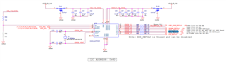
We find a issue that the voltage of CSI2_REFCLK is lower as 0.8V on TDA4AL EVM.

But in schematic as below, it voltage should be 1.8V, I think this pin output not work seems in Hi-Z status.

In ti-processor-sdk-rtos-j721s2-evm-10_01_00_04, I try to find the related function of i2c0.

Only find the definition in board_cfg.h, code path is "pdk_j721s2_10_01_00_25\packages\ti\board\src\j721s2_evm\include"

#define BOARD_I2C_PERI_CLOCK_GENERATOR                  (0x6D)

Could you help us to point how do I check this "PERIPHERAL CLOCK GENERATOR" work or not?

Thnaks,

YL

  • Hi, TI expert,

    I try to add the cdcel937 configure on k3-j721s2-common-proc-board.dts.

    But it not shown any log by cdce925_probe.

    Could you help us how to enable this function, we needs to output of CSI2_REFCLK with our goal.

    &main_i2c0 {
    	clock-frequency = <400000>;
    
    	exp1: gpio@20 {
    		compatible = "ti,tca6416";
    		reg = <0x20>;
    		gpio-controller;
    		#gpio-cells = <2>;
    		gpio-line-names = "PCIE_2L_MODE_SEL", "PCIE_2L_PERSTZ", "PCIE_2L_RC_RSTZ",
    				  "PCIE_2L_EP_RST_EN", "PCIE_1L_MODE_SEL", "PCIE_1L_PERSTZ",
    				  "PCIE_1L_RC_RSTZ", "PCIE_1L_EP_RST_EN", "PCIE_2L_PRSNT#",
    				  "PCIE_1L_PRSNT#", "CDCI1_OE1/OE4", "CDCI1_OE2/OE3", "EXP_MUX1",
    				  "EXP_MUX2", "EXP_MUX3", "GESI_EXP_PHY_RSTz";
    	};
    
    	exp2: gpio@22 {
    		compatible = "ti,tca6424";
    		reg = <0x22>;
    		gpio-controller;
    		#gpio-cells = <2>;
    		gpio-line-names = "APPLE_AUTH_RSTZ", "MLB_RSTZ", "GPIO_USD_PWR_EN", "USBC_PWR_EN",
    				  "USBC_MODE_SEL1", "USBC_MODE_SEL0", "MCAN0_EN", "MCAN0_STB#",
    				  "MUX_SPAREMUX_SPARE", "MCASP/TRACE_MUX_S0", "MCASP/TRACE_MUX_S1",
    				  "MLB_MUX_SEL", "MCAN_MUX_SEL", "MCASP2/SPI3_MUX_SEL", "PCIe_CLKREQn_MUX_SEL",
    				  "CDCI2_RSTZ", "ENET_EXP_PWRDN", "ENET_EXP_RESETZ", "ENET_I2CMUX_SEL",
    				  "ENET_EXP_SPARE2", "M2PCIE_RTSZ", "USER_INPUT1", "USER_LED1", "USER_LED2";
    
    		p09-hog {
    			/* P09 - MCASP/TRACE_MUX_S0 */
    			gpio-hog;
    			gpios = <9 GPIO_ACTIVE_HIGH>;
    			output-low;
    			line-name = "MCASP/TRACE_MUX_S0";
    		};
    
    		p10-hog {
    			/* P10 - MCASP/TRACE_MUX_S1 */
    			gpio-hog;
    			gpios = <10 GPIO_ACTIVE_HIGH>;
    			output-high;
    			line-name = "MCASP/TRACE_MUX_S1";
    		};
    	};
    
    	cdcel937: clock-generator@6d {
    		compatible = "ti,cdce937";
    		reg = <0x6d>;
    		#clock-cells = <1>;
    	};
    };

    Thanks,

    YL

  • Hi,

    Could you help us to point how do I check this "PERIPHERAL CLOCK GENERATOR" work or not?

    You can simply try probing the device to see if you are able to communicate.

    Thanks,

    Neehar

  • Following up, is this issue still open?

    Thanks,

    Neehar