Part Number: TDA4AEN-Q1
Tool/software:
Hi Team,
I'm using PSDK version 10.x on TDA4AEN based custom board.
Application is to configure 4 socket CAN channels from the A53 core.
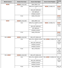
I see that MCU CAN clock is configured to 20MHz but Main CAN is configured to 80MHz by default.
Is there a way to configure the MCU MCAN clocks in the PSDK.
Below is the details of the CAN channels:
|
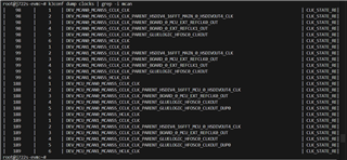
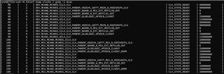
root@j722s-evm:/opt/aptiv_apps# ip -details link show mcu_mcan0 7: mcu_mcan0: <NOARP,ECHO> mtu 72 qdisc noop state DOWN mode DEFAULT group default qlen 10 link/can promiscuity 0 allmulti 0 minmtu 0 maxmtu 0 can <FD> state STOPPED (berr-counter tx 0 rx 0) restart-ms 0 bitrate 500000 sample-point 0.750 tq 250 prop-seg 3 phase-seg1 2 phase-seg2 2 sjw 2 brp 5 m_can: tseg1 2..256 tseg2 2..128 sjw 1..128 brp 1..512 brp_inc 1 m_can: dtseg1 1..32 dtseg2 1..16 dsjw 1..16 dbrp 1..32 dbrp_inc 1 clock 20000000 numtxqueues 1 numrxqueues 1 gso_max_size 65536 gso_max_segs 65535 tso_max_size 65536 tso_max_segs 65535 gro_max_size 65536 gso_ipv4_max_size 65536 gro_ipv4_max_size 65536 parentbus pl root@j722s-evm:/opt/aptiv_apps# ip -details link show mcu_mcan1 4: mcu_mcan1: <NOARP,ECHO> mtu 72 qdisc noop state DOWN mode DEFAULT group default qlen 10 link/can promiscuity 0 allmulti 0 minmtu 0 maxmtu 0 can <FD> state STOPPED (berr-counter tx 0 rx 0) restart-ms 0 bitrate 500000 sample-point 0.750 tq 250 prop-seg 3 phase-seg1 2 phase-seg2 2 sjw 2 brp 5 m_can: tseg1 2..256 tseg2 2..128 sjw 1..128 brp 1..512 brp_inc 1 m_can: dtseg1 1..32 dtseg2 1..16 dsjw 1..16 dbrp 1..32 dbrp_inc 1 clock 20000000 numtxqueues 1 numrxqueues 1 gso_max_size 65536 gso_max_segs 65535 tso_max_size 65536 tso_max_segs 65535 gro_max_size 65536 gso_ipv4_max_size 65536 gro_ipv4_max_size 65536 parentbus pl root@j722s-evm:/opt/aptiv_apps# ip -details link show main_mcan0 5: main_mcan0: <NO-CARRIER,NOARP,UP,ECHO> mtu 72 qdisc pfifo_fast state DOWN mode DEFAULT group default qlen 10 link/can promiscuity 0 allmulti 0 minmtu 0 maxmtu 0 can <FD> state BUS-OFF (berr-counter tx 248 rx 0) restart-ms 0 bitrate 500000 sample-point 0.750 tq 250 prop-seg 3 phase-seg1 2 phase-seg2 2 sjw 2 brp 20 m_can: tseg1 2..256 tseg2 2..128 sjw 1..128 brp 1..512 brp_inc 1 dbitrate 2000000 dsample-point 0.750 dtq 25 dprop-seg 9 dphase-seg1 5 dphase-seg2 5 dsjw 5 dbrp 2 m_can: dtseg1 1..32 dtseg2 1..16 dsjw 1..16 dbrp 1..32 dbrp_inc 1 clock 80000000 numtxqueues 1 numrxqueues 1 gso_max_size 65536 gso_max_segs 65535 tso_max_size 65536 tso_max_segs 65535 gro_max_size 65536 gso_ipv4_max_size 65536 gro_ipv4_max_size 65536 parentbus pl root@j722s-evm:/opt/aptiv_apps# ip -details link show main_mcan1 6: main_mcan1: <NOARP,ECHO> mtu 16 qdisc noop state DOWN mode DEFAULT group default qlen 10 link/can promiscuity 0 allmulti 0 minmtu 0 maxmtu 0 can state STOPPED (berr-counter tx 0 rx 0) restart-ms 0 m_can: tseg1 2..256 tseg2 2..128 sjw 1..128 brp 1..512 brp_inc 1 m_can: dtseg1 1..32 dtseg2 1..16 dsjw 1..16 dbrp 1..32 dbrp_inc 1 clock 80000000 numtxqueues 1 numrxqueues 1 gso_max_size 65536 gso_max_segs 65535 tso_max_size 65536 tso_max_segs 65535 gro_max_size 65536 gso_ipv4_max_size 65536 gro_ipv4_max_size 65536 parentbus pl |
I have tried to look into the mcan kernel driver files but could not find any configuration nor in the dts file.
Kindly have a look into this request at the earliest.