This thread has been locked.

If you have a related question, please click the "Ask a related question" button in the top right corner. The newly created question will be automatically linked to this question.

PROCESSOR-SDK-AM62X: AM62x PRU IEP timer documentation.

Part Number: PROCESSOR-SDK-AM62X

Tool/software:

Hi all!

Am looking for more detail on the PRU IEP timer, specifically registers & bitfields.

I've found the Datasheet, Technical Reference Manual & the header file at; pru-icss/6.3.0-r0/git/include/am62x/pru_iep.h 

Within the PDFs I've found IEP timer references but not a register description, hopefully I've missed something obvious.


I note that the header file differs from others e.g. the pru_iep.h headers for k2g, am571x, am335x, am437x, am572x all contain a definition for CMP0_RST_CNT_EN but there doesn't appear to be one for the am62x?

  • Hello,

    Some peripherals within the PRU Subsystem are exactly the same on all processors with a PRU, like the UART peripheral. However, some of them do get updated. It looks like IEP is one of those peripherals that is slightly different on different devices.

    Can you help me understand what you are trying to do? e.g., port the AM335x IEP timer example to AM62x?
    https://git.ti.com/cgit/pru-software-support-package/pru-software-support-package/tree/examples/am335x/PRU_IEP/PRU_IEP.c

    Other than that, the resource I am aware of with information about programming the IEP timer is the TRM section "PRUSS IEP". And I do see register definitions in TRM chapter 14 Registers > PRUSS Registers > "IEP0 Registers".

    Regards,

    Nick

  • Hi Nick!

    I'm interested to use the IEP timer in capture mode. I'm looking to capture the time delay between 2 inputs. So I guess in an ideal world one input would reset the capture timer via interrupt & the other input would read one of the capture registers for passing onto userspace.

    Hence looking through the examples for capture implementations.

    The TRM Chapter 14 you reference, does the timer features start at section 14.3.5.1.216 IEP0_GLOBAL_CFG_REG Registers of the techincal reference manual?

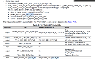
    Related question, struggling to see how/where the PR_IEP_EDC_LATCH_INx pins might be physically on the AM62x?

  • Hello,

    You can find the IEP register list at the top of the PRU section. e.g., this is what I see on the TRM version that I am currently looking at:

    You can find the input signals to the PRU - I assume you are looking for PR0_IEP0_EDIO_DATA_IN_OUTnn - in the AM62x datasheet, Terminal configuration and functions > Signal descriptions > PRUSS

    Regards,

    Nick

  • I was looking for these signals:

     I
    Think they're referenced here as well (apologies for page-break screenshot)


    Might also be worth sanity-checking, I'm interested in those signals because it looks to me like they can be used to trigger a capture of the IEP timer & hopefully also a reset.

    However I think it could also be acceptable if I could use general inputs to the PRU to trigger interrupts & "manually" reset the timer & read it's value accordingly. Am saying that in the event that those LATCH_INx signals are available but not accessible in my hardware.

  • Hello,

    Summary

    Ok, so the unfortunate news is that I do not think the LATCH_IN signals are pinned out on AM62x.

    The PRUSS on AM62x is a subset of the PRU-ICSS that you would find on a device like AM263x. There are some minor differences like clock frequency, but most of the differences are that the industrial networking signals are not pinned out on AM62x. That is why you can do PRU Ethernet on devices like AM64x & AM263x, but not AM62x (and why it's the PRU Subsystem / PRUSS instead of the PRU Industrial Communications Subsystem / PRU-ICSS).

    It looks like LATCH_IN is one of the signals that did not get pinned out. When I check the AM64x datasheet I can see the PRU's EDC_LATCH_IN signals in the pinmux, but we do not see that for AM62x.

    Backup: TRM snippets 

    Not sure if the below screenshots from the TRM will be helpful, that is what I referenced to make sure that LATCH_IN was actually a separate signal input, and not an internal mux to send pinmux signal PR0_IEP0_EDIO_DATA_IN_OUT somewhere else inside the chip.

    Regards,

    Nick