Tool/software:
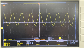
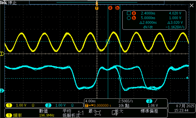
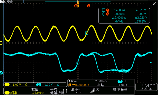
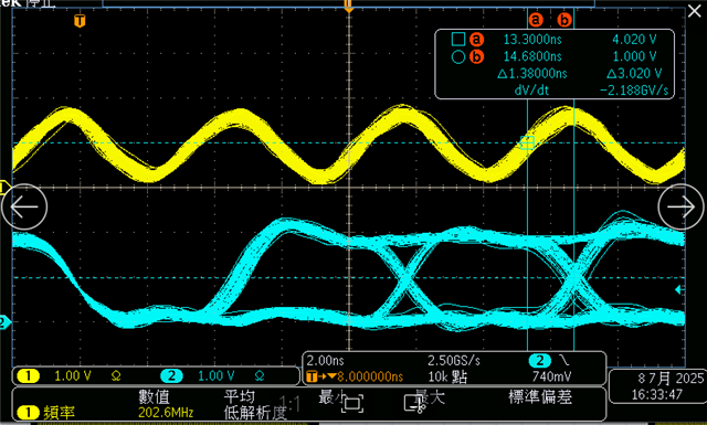
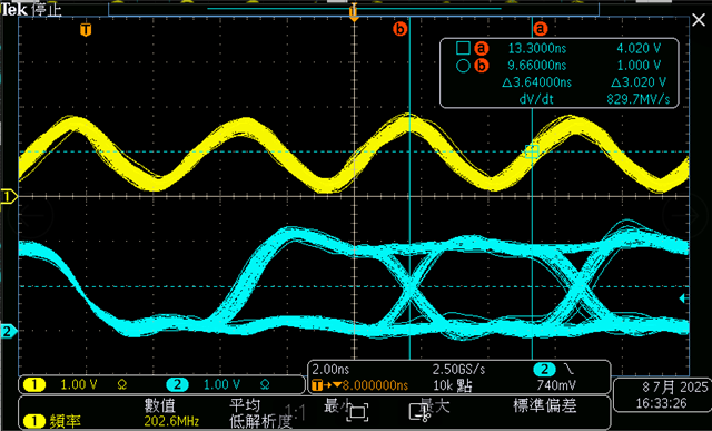
May I ask if the driving strength of the eMMC can be adjusted? If so, how can it be configured? We are currently observing signal attenuation on the CLK line, and the CLK frequency is 200 MHz.
Tool/software:
May I ask if the driving strength of the eMMC can be adjusted? If so, how can it be configured? We are currently observing signal attenuation on the CLK line, and the CLK frequency is 200 MHz.