This thread has been locked.

If you have a related question, please click the "Ask a related question" button in the top right corner. The newly created question will be automatically linked to this question.

TDA4VM: How to configure the 960 CSI-2 TX PORT1 in the TI device tree?

Part Number: TDA4VM

Tool/software:

Hi,

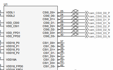
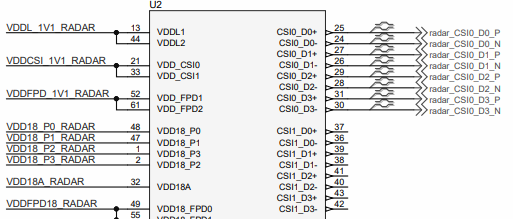
I've configured the corresponding registers in the 960 driver to enable concurrent forwarding of the RX video stream on both CSI-2 TX port0 and port1. However, currently only port0 can output two video streams, while port1 fails to output. Do I need to enable "CSI-2 Output 1" in the k3-j721e-evm-fusion.dtso file to resolve the port1 output issue? How should the device tree be configured to resolve this?

Thanks!

  • Hi Ying Li,

    Can you please share the i2c writes that are happening to enable forwarding to both the ports? 

    Regards,

    Brijesh

  • Hi,

    I am reading and writing registers in the 960 driver. The following are the register values read when starting and stopping the video stream. Thank you very much!

    [    5.875662] --------------0x32:13
    [    5.891366] -----------------0x33:40
    
    
    Setting pipeline to PLAYING ...
    New clock: GstSystemClock
    [  390.462558] ---------------0x20:f0
    [  390.470417] -----------------0x33:41
    [  390.473981] enable RX port 0
    [  390.477203] ---------------0x20:f0
    [  390.480946] ---------------0x20:fc
    [  390.484688] ---------------0x20:c
    [  390.862125] enable RX port 1
    [  390.865350] ---------------0x20:fc
    [  390.869008] ---------------0x20:fc
    [  390.872748] ---------------0x20:c
    [  391.146986] ds90ub960 5-003d: rx0 CSI error: 0xc
    [  391.151604] ds90ub960 5-003d: rx0 CSI checksum error
    [  391.156563] ds90ub960 5-003d: rx0 CSI length error
    [  391.250129] enable RX port 2
    [  391.253346] ---------------0x20:fc
    [  391.256999] ---------------0x20:fc
    [  391.260739] ---------------0x20:c
    
    Redistribute latency...
    handling interrupt.:99.
    Interrupt: Stopping pipeline ...
    Execution ended after 0:00:03.348225805
    Setting pipeline to NULL ...
    [  393.779373] ---------------0x20:1c
    [  393.803359] ---------------0x20:3c
    [  393.827340] ---------------0x20:7c
    [  393.835163] -----------------0x33:40
    Freeing pipeline ...

  • Hi Ying,

    Can you answer a few questions so I can better understand your intended configuration?

    • How many cameras are you using with the 960? Which RX ports are they connected to?
    • Which RX ports should be forwarded to CSI port 0? Which RX ports should be forwarded to CSI port 1?
    • Can you share the CSI output settings that should be used? How many lanes, what is the lane rate, and should continuous clock be enabled?

    Best,

    Lucas

  • Hi Lucas

    Here are the responses to your several questions.

    1.Currently, the 960 is connected to 4 sensors with a frame rate of 30 FPS, a resolution of 1920×1280, and the image format is raw12.My sensor is ox03c10 and serializer is ub953.

    2. Originally, all four RX channels were forwarded to CSI port 0. However, the 960 driver reports errors: "rx1 buffer error ds90ub960 5-003d: rx2 buffer error ds90ub960 5-003d: rx3 buffer error". By referring to the data sheet, the error cause is identified as data overflow. Therefore, I now plan to configure RX1 and RX2 to use CSI port 0, and RX3 and RX4 to use CSI port 1.

    3. By printing the register values related to the 960 driver, it is confirmed that the CSI-2 lane count is 4 and the CSI-2 Transmitter Data Rate is 1.6Gbps. But now I am experiencing data overflow in reception. I'm not sure if I should enable the continuous clock.

    Thanks!

  • Hi Lucas

    Could you kindly help me check if there are any issues with my device tree, including aspects related to clocks? I'm not sure if the clock is causing this issue. Thank you again.

    // SPDX-License-Identifier: GPL-2.0
    /*
     * DT Overlay for Fusion (FPD-Link III) board on J721E EVM
     * https://svtronics.com/portfolio/evm577pfusion-v1-0-fusion/
     *
     * Copyright (C) 2023 Texas Instruments Incorporated - http://www.ti.com/
     */
    
    /dts-v1/;
    /plugin/;
    
    #include <dt-bindings/gpio/gpio.h>
    
    &{/} {
    	clk_fusion_25M_fixed: fixed-clock-25M {
    		compatible = "fixed-clock";
    		#clock-cells = <0>;
    		clock-frequency = <25000000>;
    	};
    };
    
    
    &main_i2c6 {
    	#address-cells = <1>;
    	#size-cells = <0>;
    	status = "okay";
    
    	deser@3d {
    		compatible = "ti,ds90ub960-q1";
    		reg = <0x3d>;
    		clocks = <&clk_fusion_25M_fixed>;
    		clock-names = "refclk";
    		i2c-alias-pool = <0x4a 0x4b 0x4c 0x4d 0x4e 0x4f>;
    
    		ds90ub960_0_ports: ports {
    			#address-cells = <1>;
    			#size-cells = <0>;
    
    			/* CSI-2 TX */
    			port@4 {
    				reg = <4>;
    				ds90ub960_0_csi_out: endpoint {
    					clock-lanes = <0>;
    					data-lanes = <1 2 3 4>;
    					link-frequencies = /bits/ 64 <800000000>;
    					remote-endpoint = <&csi2_phy0>;
    				};
    			};
    
    		};
    
    		ds90ub960_0_links: links {
    			#address-cells = <1>;
    			#size-cells = <0>;
    		};
    	};
    
    	deser@36 {
    	    status = "disable";
    		compatible = "ti,ds90ub960-q1";
    		reg = <0x36>;
    		clocks = <&clk_fusion_25M_fixed>;
    		clock-names = "refclk";
    		i2c-alias-pool = <0x5a 0x5b 0x5c 0x5d 0x5e 0x5f>;
    
    		ds90ub960_1_ports: ports {
    			#address-cells = <1>;
    			#size-cells = <0>;
    
    			/* CSI-2 TX */
    			port@4 {
    				reg = <4>;
    				ds90ub960_1_csi_out: endpoint {
    					clock-lanes = <0>;
    					data-lanes = <1 2 3 4>;
    					link-frequencies = /bits/ 64 <800000000>;
    					remote-endpoint = <&csi2_phy1>;
    				};
    			};
    		};
    
    		ds90ub960_1_links: links {
    			#address-cells = <1>;
    			#size-cells = <0>;
    		};
    	};
    };
    
    &csi0_port0 {
    	status = "okay";
    
    	csi2_phy0: endpoint {
    		remote-endpoint = <&ds90ub960_0_csi_out>;
    		clock-lanes = <0>;
    		data-lanes = <1 2 3 4>;
    		link-frequencies = /bits/ 64 <800000000>;
    	};
    };
    
    &csi1_port0 {
    	status = "okay";
    
    	csi2_phy1: endpoint {
    		remote-endpoint = <&ds90ub960_1_csi_out>;
    		clock-lanes = <0>;
    		data-lanes = <1 2 3 4>;
    		link-frequencies = /bits/ 64 <800000000>;
    	};
    };
    
    // SPDX-License-Identifier: GPL-2.0
    /*
     * IMX390 FPD-Link 3 Camera Module
     * https://www.d3engineering.co/product/designcore-d3rcm-imx390-953-rugged-camera-module/
     *
     * Copyright (c) 2023 Texas Instruments Incorporated - http://www.ti.com/
     */
    
    /dts-v1/;
    /plugin/;
    
    #include <dt-bindings/gpio/gpio.h>
    
    &ds90ub960_0_ports {
    	#address-cells = <1>;
    	#size-cells = <0>;
    
    	/* FPDLink RX 0 */
    	port@0 {
    		reg = <0>;
    
    		ub960_fpd3_1_in: endpoint {
    			remote-endpoint = <&ub953_1_out>;
    		};
    	};
    };
    
    &ds90ub960_0_links {
    	#address-cells = <1>;
    	#size-cells = <0>;
    
    	link@0 {
    		reg = <0>;
    		i2c-alias = <0x44>;
    
    		ti,rx-mode = <3>;
    
    		serializer: serializer {
    			compatible = "ti,ds90ub953-q1";
    			gpio-controller;
    			#gpio-cells = <2>;
    
    			#clock-cells = <0>;
    
    			ports {
    				#address-cells = <1>;
    				#size-cells = <0>;
    
    				port@0 {
    					reg = <0>;
    					ub953_1_in: endpoint {
    						data-lanes = <1 2 3 4>;
    						remote-endpoint = <&sensor_1_out>;
    					};
    				};
    
    				port@1 {
    					reg = <1>;
    
    					ub953_1_out: endpoint {
    						remote-endpoint = <&ub960_fpd3_1_in>;
    					};
    				};
    			};
    
    			i2c {
    				#address-cells = <1>;
    				#size-cells = <0>;
    
    				sensor@36 {
    				    compatible = "ovti,ox03c10";
    					reg = <0x36>;
    
    					clocks = <&serializer>;
    					clock-names = "inck";
    					assigned-clocks = <&serializer>;
    					assigned-clock-rates = <27000000>;
    
    					port {
    						sensor_1_out: endpoint {
    							remote-endpoint = <&ub953_1_in>;
    						};
    					};
    				};
    			};
    		};
    	};
    
    
    };
    

  • Hi Ying,

    Thank you for answering my questions. I reviewed your device tree and don't believe there is any issue.

    Can you try enabling continuous clock and forward all 4 camera streams to one CSI port? Continuous clock setting will increase your output bandwidth so this may prevent buffer overflow.

    If you still see buffer overflow, can you try running the following register writes to forward RX0/1 to CSI port 0 and RX2/3 to CSI port 1?

    0x20=0xf0

    0x20=0xfc

    0x20=0x0c

    Best,

    Lucas

  • Hi,

    Thanks!Is it necessary to add port5 in the k3-j721e-evmfusion.dtso file to enable 'CSI-2 Output 1'?

  • Hi Ying,

    I am not very familiar with the dtso file as I support FPD-Link SerDes products like the 960 and do not support the TDA4VM. However the settings I see in your dtso file appear correct.

    The 960 has 4 FPD input ports and 2 CSI output ports so I'm not sure what port5 refers to. I do see in your file that you have configurations for csi0_port0 and csi1_port0, which I assume corresponds to the 2 CSI output ports. You can check if CSI output is enabled with the following register reads/writes.

    • Write 0x32=0x01 to select CSI port 0
    • Read 0x33. If bit 0=b1, then output is enabled
    • Write 0x32=0x12 to select CSI port 1
    • Read 0x33. If bit 0=b1, then output is enabled

    If you are still having issues with your configuration, can you share a full register dump with me under the following conditions? I'd like to review and check for other errors.

    • Write 0x4c=0x01 to select RX port 0
    • Write 0x32=0x01 to select CSI port 0
    • Read all registers and share values
    • Write 0x32=0x12 to select CSI port 1
    • Read all registers and share values

    Best,

    Lucas

  • Hi Lucas,

    Thank you very much for your help. 

    1. I previously tried to forward RX0/1 to CSI port 0 and RX2/3 to CSI port 1, but only CSI port 0 could output the video stream.  After reviewing the schematic, I noticed that each UB960 chip only has one CSI port enabled. Does this mean the board cannot support the configuration of forwarding RX0/1 to CSI port 0 and RX2/3 to CSI port 1 simultaneously?

    2. Can I use the 960 chip on the radar to transmit the other two video streams?

    Thank you.

  • Hi Ying,

    If CSI port 1 output pins of the 960 are not connected to anything, then the port cannot be used. I'm unsure how each of these 960 devices are connected so I cannot comment if the other 960 chip can be used to transmit the other 2 streams.

    What board are you using which contains the 960? Is this a custom board you designed, or did it come from TI or another vendor? Can you share a block diagram showing how each 960 is connected within the system?

    Can you share the following information about each of the video streams? With this information I can determine if one CSI output port should be capable of transmitting the total bandwidth.

    • Active horizontal resolution (number of pixels)
    • Active vertical resolution (number of lines)
    • Total vertical resolution including blanking (number of lines)
    • Frame rate (fps)
    • Video format (bits per pixel)

    Best,

    Lucas

  • Hi Lucas,

    I am using TI's development board and deserializer board, as shown in the figure below.

    My sensor is OX03C10, with output configuration of 1920×1280, 30 fps, raw12. Vertical Blanking Lines is 1365. The serializer is ds90ub953. Theoretically, it should not exceed the bandwidth of 960, but in practice, errors keep occurring.


  • Hi Lucas,

    My problem has been solved. I used the two ub960 chips on this deserializer board to transmit two video streams respectively. Thank you very much for your help these days.

  • Hi Ying,

    I'm glad the issue is now resolved. Let me know if you have any follow up questions.

    Best,

    Lucas