This thread has been locked.

If you have a related question, please click the "Ask a related question" button in the top right corner. The newly created question will be automatically linked to this question.

J784S4XEVM: USB VC drivers for USB camera bringup

Part Number: J784S4XEVM

Tool/software:

Hello there,

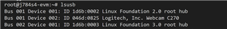
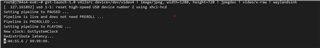
we want to bring up USB Camer on custom Linux with J784S4XEVM board.

could you please share the steps to do it or documentation where things are given ?

with TI documentation the build is thru Yocto Linux we want to do the bring up directly on the booted board with existing kernel 

thanks and kind regards 

Mohan

  • Hi Mohan,

    The j784s4 sdk by default has support for usb vc drivers. We have tested this on our end and it is working fine.

    Following are the steps we followed:

    • Connect the USB type C camera.
    • Boot upto linux.
    • Enter the following commands
      • >lsusb
      • Output logs:
        • The logitech string in the log indicates that the USB camera is detected.
      • >gst-launch-1.0 v4l2src device=/dev/video4 ! image/jpeg, width=1280, height=720 ! jpegdec ! video/x-raw ! waylandsink
      • Output logs:
        • We were able to see the display after connected the dp cable from the monitor to the display port of the J784S4 board.

    Note: The /dev/videox can be checked when using the /dev/videox that was created after connecting the webcam to the board(ie: by comparing the /dev/videox devices before and after connecting the webcam)

    Regards

    Gokul

  • Hello Gokul,

    thanks for prompt response.

    we have our custom Linux OS where no USB drivers, no Video Class drivers, *it is not TI J784s4 SDK Linux*

    we want to bringup the Camera on our in house Linux kernel we are bringup 

    in this scenario could you please check and let us know how to bring-up/get the USB drivers 

    thanks

    Mohan  

  • Hi Mohan,

    Can you enable the below 2 configs from menuconfig and give a try:

    • CONFIG_USB_VIDEO_CLASS
    • CONFIG_USB_VIDEO_CLASS_INPUT_EVDEV

    Regards

    Gokul

  • Hi Gokul,

    we have done our kernel build and USB VC(UVC) drivers are installed but lsusb is not showing anything

    we have connect camera to both USB Type C port and Type A port but no respose.

    could you please share any possible fix

    thanks

    Mohan

  • Hi Mohan,

    Can you share the device tree file(k3-j784s4-evm.dtb) which you are using?

    Regards

    Gokul

  • Hello Gokul,

    Please find here dtb files

    please check and let us know

    uploading as txt file to enable upload 

    thanks, Mohan

    // SPDX-License-Identifier: GPL-2.0-only OR MIT
    /*
     * Copyright (C) 2022-2024 Texas Instruments Incorporated - https://www.ti.com/
     *
     * EVM Board Schematics: https://www.ti.com/lit/zip/sprr458
     */
    
    /dts-v1/;
    
    #include <dt-bindings/net/ti-dp83867.h>
    #include <dt-bindings/gpio/gpio.h>
    #include "k3-j784s4.dtsi"
    
    / {
    	compatible = "ti,j784s4-evm", "ti,j784s4";
    	model = "Texas Instruments J784S4 EVM";
    
    	chosen {
    		stdout-path = "serial2:115200n8";
    	};
    
    	aliases {
    		serial0 = &wkup_uart0;
    		serial1 = &mcu_uart0;
    		serial2 = &main_uart8;
    		mmc0 = &main_sdhci0;
    		mmc1 = &main_sdhci1;
    		i2c0 = &wkup_i2c0;
    		i2c3 = &main_i2c0;
    		ethernet0 = &mcu_cpsw_port1;
    		ethernet1 = &main_cpsw1_port1;
    	};
    
    	memory@80000000 {
    		device_type = "memory";
    		bootph-all;
    		/* 32G RAM */
    		reg = <0x00000000 0x80000000 0x00000000 0x80000000>,
    		      <0x00000008 0x80000000 0x00000007 0x80000000>;
    	};
    
    	reserved_memory: reserved-memory {
    		#address-cells = <2>;
    		#size-cells = <2>;
    		ranges;
    
    		secure_ddr: optee@9e800000 {
    			reg = <0x00 0x9e800000 0x00 0x01800000>;
    			no-map;
    		};
    
    		mcu_r5fss0_core0_dma_memory_region: r5f-dma-memory@a0000000 {
    			compatible = "shared-dma-pool";
    			reg = <0x00 0xa0000000 0x00 0x100000>;
    			no-map;
    		};
    
    		mcu_r5fss0_core0_memory_region: r5f-memory@a0100000 {
    			compatible = "shared-dma-pool";
    			reg = <0x00 0xa0100000 0x00 0xf00000>;
    			no-map;
    		};
    
    		mcu_r5fss0_core1_dma_memory_region: r5f-dma-memory@a1000000 {
    			compatible = "shared-dma-pool";
    			reg = <0x00 0xa1000000 0x00 0x100000>;
    			no-map;
    		};
    
    		mcu_r5fss0_core1_memory_region: r5f-memory@a1100000 {
    			compatible = "shared-dma-pool";
    			reg = <0x00 0xa1100000 0x00 0xf00000>;
    			no-map;
    		};
    
    		main_r5fss0_core0_dma_memory_region: r5f-dma-memory@a2000000 {
    			compatible = "shared-dma-pool";
    			reg = <0x00 0xa2000000 0x00 0x100000>;
    			no-map;
    		};
    
    		main_r5fss0_core0_memory_region: r5f-memory@a2100000 {
    			compatible = "shared-dma-pool";
    			reg = <0x00 0xa2100000 0x00 0xf00000>;
    			no-map;
    		};
    
    		main_r5fss0_core1_dma_memory_region: r5f-dma-memory@a3000000 {
    			compatible = "shared-dma-pool";
    			reg = <0x00 0xa3000000 0x00 0x100000>;
    			no-map;
    		};
    
    		main_r5fss0_core1_memory_region: r5f-memory@a3100000 {
    			compatible = "shared-dma-pool";
    			reg = <0x00 0xa3100000 0x00 0xf00000>;
    			no-map;
    		};
    
    		main_r5fss1_core0_dma_memory_region: r5f-dma-memory@a4000000 {
    			compatible = "shared-dma-pool";
    			reg = <0x00 0xa4000000 0x00 0x100000>;
    			no-map;
    		};
    
    		main_r5fss1_core0_memory_region: r5f-memory@a4100000 {
    			compatible = "shared-dma-pool";
    			reg = <0x00 0xa4100000 0x00 0xf00000>;
    			no-map;
    		};
    
    		main_r5fss1_core1_dma_memory_region: r5f-dma-memory@a5000000 {
    			compatible = "shared-dma-pool";
    			reg = <0x00 0xa5000000 0x00 0x100000>;
    			no-map;
    		};
    
    		main_r5fss1_core1_memory_region: r5f-memory@a5100000 {
    			compatible = "shared-dma-pool";
    			reg = <0x00 0xa5100000 0x00 0xf00000>;
    			no-map;
    		};
    
    		main_r5fss2_core0_dma_memory_region: r5f-dma-memory@a6000000 {
    			compatible = "shared-dma-pool";
    			reg = <0x00 0xa6000000 0x00 0x100000>;
    			no-map;
    		};
    
    		main_r5fss2_core0_memory_region: r5f-memory@a6100000 {
    			compatible = "shared-dma-pool";
    			reg = <0x00 0xa6100000 0x00 0xf00000>;
    			no-map;
    		};
    
    		main_r5fss2_core1_dma_memory_region: r5f-dma-memory@a7000000 {
    			compatible = "shared-dma-pool";
    			reg = <0x00 0xa7000000 0x00 0x100000>;
    			no-map;
    		};
    
    		main_r5fss2_core1_memory_region: r5f-memory@a7100000 {
    			compatible = "shared-dma-pool";
    			reg = <0x00 0xa7100000 0x00 0xf00000>;
    			no-map;
    		};
    
    		c71_0_dma_memory_region: c71-dma-memory@a8000000 {
    			compatible = "shared-dma-pool";
    			reg = <0x00 0xa8000000 0x00 0x100000>;
    			no-map;
    		};
    
    		c71_0_memory_region: c71-memory@a8100000 {
    			compatible = "shared-dma-pool";
    			reg = <0x00 0xa8100000 0x00 0xf00000>;
    			no-map;
    		};
    
    		c71_1_dma_memory_region: c71-dma-memory@a9000000 {
    			compatible = "shared-dma-pool";
    			reg = <0x00 0xa9000000 0x00 0x100000>;
    			no-map;
    		};
    
    		c71_1_memory_region: c71-memory@a9100000 {
    			compatible = "shared-dma-pool";
    			reg = <0x00 0xa9100000 0x00 0xf00000>;
    			no-map;
    		};
    
    		c71_2_dma_memory_region: c71-dma-memory@aa000000 {
    			compatible = "shared-dma-pool";
    			reg = <0x00 0xaa000000 0x00 0x100000>;
    			no-map;
    		};
    
    		c71_2_memory_region: c71-memory@aa100000 {
    			compatible = "shared-dma-pool";
    			reg = <0x00 0xaa100000 0x00 0xf00000>;
    			no-map;
    		};
    
    		c71_3_dma_memory_region: c71-dma-memory@ab000000 {
    			compatible = "shared-dma-pool";
    			reg = <0x00 0xab000000 0x00 0x100000>;
    			no-map;
    		};
    
    		c71_3_memory_region: c71-memory@ab100000 {
    			compatible = "shared-dma-pool";
    			reg = <0x00 0xab100000 0x00 0xf00000>;
    			no-map;
    		};
    	};
    
    	evm_12v0: regulator-evm12v0 {
    		/* main supply */
    		compatible = "regulator-fixed";
    		regulator-name = "evm_12v0";
    		regulator-min-microvolt = <12000000>;
    		regulator-max-microvolt = <12000000>;
    		regulator-always-on;
    		regulator-boot-on;
    	};
    
    	vsys_3v3: regulator-vsys3v3 {
    		/* Output of LM5140 */
    		compatible = "regulator-fixed";
    		regulator-name = "vsys_3v3";
    		regulator-min-microvolt = <3300000>;
    		regulator-max-microvolt = <3300000>;
    		vin-supply = <&evm_12v0>;
    		regulator-always-on;
    		regulator-boot-on;
    	};
    
    	vsys_5v0: regulator-vsys5v0 {
    		/* Output of LM5140 */
    		compatible = "regulator-fixed";
    		regulator-name = "vsys_5v0";
    		regulator-min-microvolt = <5000000>;
    		regulator-max-microvolt = <5000000>;
    		vin-supply = <&evm_12v0>;
    		regulator-always-on;
    		regulator-boot-on;
    	};
    
    	vdd_mmc1: regulator-sd {
    		/* Output of TPS22918 */
    		compatible = "regulator-fixed";
    		regulator-name = "vdd_mmc1";
    		regulator-min-microvolt = <3300000>;
    		regulator-max-microvolt = <3300000>;
    		regulator-boot-on;
    		enable-active-high;
    		vin-supply = <&vsys_3v3>;
    		gpio = <&exp2 2 GPIO_ACTIVE_HIGH>;
    	};
    
    	vdd_sd_dv: regulator-TLV71033 {
    		/* Output of TLV71033 */
    		compatible = "regulator-gpio";
    		regulator-name = "tlv71033";
    		pinctrl-names = "default";
    		pinctrl-0 = <&vdd_sd_dv_pins_default>;
    		regulator-min-microvolt = <1800000>;
    		regulator-max-microvolt = <3300000>;
    		regulator-boot-on;
    		vin-supply = <&vsys_5v0>;
    		gpios = <&main_gpio0 8 GPIO_ACTIVE_HIGH>;
    		states = <1800000 0x0>,
    			 <3300000 0x1>;
    	};
    
    	dp0_pwr_3v3: regulator-dp0-prw {
    		compatible = "regulator-fixed";
    		regulator-name = "dp0-pwr";
    		regulator-min-microvolt = <3300000>;
    		regulator-max-microvolt = <3300000>;
    		gpio = <&exp4 0 GPIO_ACTIVE_HIGH>;
    		enable-active-high;
    	};
    
    	dp0: connector-dp0 {
    		compatible = "dp-connector";
    		label = "DP0";
    		type = "full-size";
    		dp-pwr-supply = <&dp0_pwr_3v3>;
    
    		port {
    			dp0_connector_in: endpoint {
    				remote-endpoint = <&dp0_out>;
    			};
    		};
    	};
    
    	transceiver0: can-phy0 {
    		compatible = "ti,tcan1042";
    		#phy-cells = <0>;
    		max-bitrate = <5000000>;
    		pinctrl-names = "default";
    		pinctrl-0 = <&mcu_mcan0_gpio_pins_default>;
    		standby-gpios = <&wkup_gpio0 69 GPIO_ACTIVE_HIGH>;
    	};
    
    	transceiver1: can-phy1 {
    		compatible = "ti,tcan1042";
    		#phy-cells = <0>;
    		max-bitrate = <5000000>;
    		pinctrl-names = "default";
    		pinctrl-0 = <&mcu_mcan1_gpio_pins_default>;
    		standby-gpios = <&wkup_gpio0 2 GPIO_ACTIVE_HIGH>;
    	};
    
    	transceiver2: can-phy2 {
    		/* standby pin has been grounded by default */
    		compatible = "ti,tcan1042";
    		#phy-cells = <0>;
    		max-bitrate = <5000000>;
    	};
    
    	transceiver3: can-phy3 {
    		compatible = "ti,tcan1042";
    		#phy-cells = <0>;
    		max-bitrate = <5000000>;
    		standby-gpios = <&exp2 7 GPIO_ACTIVE_HIGH>;
    		mux-states = <&mux1 1>;
    	};
    
    	mux1: mux-controller {
    		compatible = "gpio-mux";
    		#mux-state-cells = <1>;
    		mux-gpios = <&exp2 14 GPIO_ACTIVE_HIGH>;
    	};
    };
    
    &wkup_gpio0 {
    	status = "okay";
    };
    
    &main_pmx0 {
    	bootph-all;
    	main_cpsw2g_default_pins: main-cpsw2g-default-pins {
    		pinctrl-single,pins = <
    			J784S4_IOPAD(0x0b8, PIN_INPUT, 6) /* (AC34) MCASP1_ACLKX.RGMII1_RD0 */
    			J784S4_IOPAD(0x0a0, PIN_INPUT, 6) /* (AD34) MCASP0_AXR12.RGMII1_RD1 */
    			J784S4_IOPAD(0x0a4, PIN_INPUT, 6) /* (AJ36) MCASP0_AXR13.RGMII1_RD2 */
    			J784S4_IOPAD(0x0a8, PIN_INPUT, 6) /* (AF34) MCASP0_AXR14.RGMII1_RD3 */
    			J784S4_IOPAD(0x0b0, PIN_INPUT, 6) /* (AL33) MCASP1_AXR3.RGMII1_RXC */
    			J784S4_IOPAD(0x0ac, PIN_INPUT, 6) /* (AE34) MCASP0_AXR15.RGMII1_RX_CTL */
    			J784S4_IOPAD(0x08c, PIN_INPUT, 6) /* (AE35) MCASP0_AXR7.RGMII1_TD0 */
    			J784S4_IOPAD(0x090, PIN_INPUT, 6) /* (AC35) MCASP0_AXR8.RGMII1_TD1 */
    			J784S4_IOPAD(0x094, PIN_INPUT, 6) /* (AG35) MCASP0_AXR9.RGMII1_TD2 */
    			J784S4_IOPAD(0x098, PIN_INPUT, 6) /* (AH36) MCASP0_AXR10.RGMII1_TD3 */
    			J784S4_IOPAD(0x0b4, PIN_INPUT, 6) /* (AL34) MCASP1_AXR4.RGMII1_TXC */
    			J784S4_IOPAD(0x09c, PIN_INPUT, 6) /* (AF35) MCASP0_AXR11.RGMII1_TX_CTL */
    		>;
    	};
    
    	main_cpsw2g_mdio_default_pins: main-cpsw2g-mdio-default-pins {
    		pinctrl-single,pins = <
    			J784S4_IOPAD(0x0c0, PIN_INPUT, 6) /* (AD38) MCASP1_AXR0.MDIO0_MDC */
    			J784S4_IOPAD(0x0bc, PIN_INPUT, 6) /* (AD33) MCASP1_AFSX.MDIO0_MDIO */
    		>;
    	};
    
    	main_uart8_pins_default: main-uart8-default-pins {
    		bootph-all;
    		pinctrl-single,pins = <
    			J784S4_IOPAD(0x040, PIN_INPUT, 14) /* (AF37) MCASP0_AXR0.UART8_CTSn */
    			J784S4_IOPAD(0x044, PIN_OUTPUT, 14) /* (AG37) MCASP0_AXR1.UART8_RTSn */
    			J784S4_IOPAD(0x0d0, PIN_INPUT, 11) /* (AP38) SPI0_CS1.UART8_RXD */
    			J784S4_IOPAD(0x0d4, PIN_OUTPUT, 11) /* (AN38) SPI0_CLK.UART8_TXD */
    		>;
    	};
    
    	main_i2c0_pins_default: main-i2c0-default-pins {
    		pinctrl-single,pins = <
    			J784S4_IOPAD(0x0e0, PIN_INPUT_PULLUP, 0) /* (AN36) I2C0_SCL */
    			J784S4_IOPAD(0x0e4, PIN_INPUT_PULLUP, 0) /* (AP37) I2C0_SDA */
    		>;
    	};
    
    	main_i2c5_pins_default: main-i2c5-default-pins {
    		pinctrl-single,pins = <
    			J784S4_IOPAD(0x01c, PIN_INPUT, 8) /* (AG34) MCAN15_TX.I2C5_SCL */
    			J784S4_IOPAD(0x018, PIN_INPUT, 8) /* (AK36) MCAN14_RX.I2C5_SDA */
    		>;
    	};
    
    	main_mmc1_pins_default: main-mmc1-default-pins {
    		bootph-all;
    		pinctrl-single,pins = <
    			J784S4_IOPAD(0x104, PIN_INPUT, 0) /* (AB38) MMC1_CLK */
    			J784S4_IOPAD(0x108, PIN_INPUT, 0) /* (AB36) MMC1_CMD */
    			J784S4_IOPAD(0x100, PIN_INPUT, 0) /* (No Pin) MMC1_CLKLB */
    			J784S4_IOPAD(0x0fc, PIN_INPUT, 0) /* (AA33) MMC1_DAT0 */
    			J784S4_IOPAD(0x0f8, PIN_INPUT, 0) /* (AB34) MMC1_DAT1 */
    			J784S4_IOPAD(0x0f4, PIN_INPUT, 0) /* (AA32) MMC1_DAT2 */
    			J784S4_IOPAD(0x0f0, PIN_INPUT, 0) /* (AC38) MMC1_DAT3 */
    			J784S4_IOPAD(0x0e8, PIN_INPUT, 8) /* (AR38) TIMER_IO0.MMC1_SDCD */
    		>;
    	};
    
    	vdd_sd_dv_pins_default: vdd-sd-dv-default-pins {
    		pinctrl-single,pins = <
    			J784S4_IOPAD(0x020, PIN_INPUT, 7) /* (AJ35) MCAN15_RX.GPIO0_8 */
    		>;
    	};
    
    	dp0_pins_default: dp0-default-pins {
    		pinctrl-single,pins = <
    			J784S4_IOPAD(0x0cc, PIN_INPUT, 12) /* (AM37) SPI0_CS0.DP0_HPD */
    		>;
    	};
    
    	main_i2c4_pins_default: main-i2c4-default-pins {
    		pinctrl-single,pins = <
    			J784S4_IOPAD(0x014, PIN_INPUT_PULLUP, 8) /* (AG33) MCAN14_TX.I2C4_SCL */
    			J784S4_IOPAD(0x010, PIN_INPUT_PULLUP, 8) /* (AH33) MCAN13_RX.I2C4_SDA */
    		>;
    	};
    
    	main_mcan4_pins_default: main-mcan4-default-pins {
    		pinctrl-single,pins = <
    			J784S4_IOPAD(0x088, PIN_INPUT, 0) /* (AF36) MCAN4_RX */
    			J784S4_IOPAD(0x084, PIN_OUTPUT, 0) /* (AG38) MCAN4_TX */
    		>;
    	};
    
    	main_mcan16_pins_default: main-mcan16-default-pins {
    		pinctrl-single,pins = <
    			J784S4_IOPAD(0x028, PIN_INPUT, 0) /* (AE33) MCAN16_RX */
    			J784S4_IOPAD(0x024, PIN_OUTPUT, 0) /* (AH34) MCAN16_TX */
    		>;
    	};
    
    	main_usbss0_pins_default: main-usbss0-default-pins {
    		bootph-all;
    		pinctrl-single,pins = <
    			J784S4_IOPAD(0x0ec, PIN_OUTPUT, 6) /* (AN37) TIMER_IO1.USB0_DRVVBUS */
    		>;
    	};
    };
    
    &wkup_pmx2 {
    	bootph-all;
    	wkup_uart0_pins_default: wkup-uart0-default-pins {
    		bootph-all;
    		pinctrl-single,pins = <
    			J784S4_WKUP_IOPAD(0x048, PIN_INPUT, 0) /* (K35) WKUP_UART0_RXD */
    			J784S4_WKUP_IOPAD(0x04c, PIN_OUTPUT, 0) /* (K34) WKUP_UART0_TXD */
    		>;
    	};
    
    	wkup_i2c0_pins_default: wkup-i2c0-default-pins {
    		bootph-all;
    		pinctrl-single,pins = <
    			J784S4_WKUP_IOPAD(0x98, PIN_INPUT, 0) /* (N33) WKUP_I2C0_SCL */
    			J784S4_WKUP_IOPAD(0x9c, PIN_INPUT, 0) /* (N35) WKUP_I2C0_SDA */
    		>;
    	};
    
    	mcu_uart0_pins_default: mcu-uart0-default-pins {
    		bootph-all;
    		pinctrl-single,pins = <
    			J784S4_WKUP_IOPAD(0x090, PIN_INPUT, 0) /* (H37) WKUP_GPIO0_14.MCU_UART0_CTSn */
    			J784S4_WKUP_IOPAD(0x094, PIN_OUTPUT, 0) /* (K37) WKUP_GPIO0_15.MCU_UART0_RTSn */
    			J784S4_WKUP_IOPAD(0x08c, PIN_INPUT, 0) /* (K38) WKUP_GPIO0_13.MCU_UART0_RXD */
    			J784S4_WKUP_IOPAD(0x088, PIN_OUTPUT, 0) /* (J37) WKUP_GPIO0_12.MCU_UART0_TXD */
    		>;
    	};
    
    	mcu_cpsw_pins_default: mcu-cpsw-default-pins {
    		pinctrl-single,pins = <
    			J784S4_WKUP_IOPAD(0x02c, PIN_INPUT, 0) /* (A35) MCU_RGMII1_RD0 */
    			J784S4_WKUP_IOPAD(0x028, PIN_INPUT, 0) /* (B36) MCU_RGMII1_RD1 */
    			J784S4_WKUP_IOPAD(0x024, PIN_INPUT, 0) /* (C36) MCU_RGMII1_RD2 */
    			J784S4_WKUP_IOPAD(0x020, PIN_INPUT, 0) /* (D36) MCU_RGMII1_RD3 */
    			J784S4_WKUP_IOPAD(0x01c, PIN_INPUT, 0) /* (B37) MCU_RGMII1_RXC */
    			J784S4_WKUP_IOPAD(0x004, PIN_INPUT, 0) /* (C37) MCU_RGMII1_RX_CTL */
    			J784S4_WKUP_IOPAD(0x014, PIN_OUTPUT, 0) /* (D37) MCU_RGMII1_TD0 */
    			J784S4_WKUP_IOPAD(0x010, PIN_OUTPUT, 0) /* (D38) MCU_RGMII1_TD1 */
    			J784S4_WKUP_IOPAD(0x00c, PIN_OUTPUT, 0) /* (E37) MCU_RGMII1_TD2 */
    			J784S4_WKUP_IOPAD(0x008, PIN_OUTPUT, 0) /* (E38) MCU_RGMII1_TD3 */
    			J784S4_WKUP_IOPAD(0x018, PIN_OUTPUT, 0) /* (E36) MCU_RGMII1_TXC */
    			J784S4_WKUP_IOPAD(0x000, PIN_OUTPUT, 0) /* (C38) MCU_RGMII1_TX_CTL */
    		>;
    	};
    
    	mcu_mdio_pins_default: mcu-mdio-default-pins {
    		pinctrl-single,pins = <
    			J784S4_WKUP_IOPAD(0x034, PIN_OUTPUT, 0) /* (A36) MCU_MDIO0_MDC */
    			J784S4_WKUP_IOPAD(0x030, PIN_INPUT, 0) /* (B35) MCU_MDIO0_MDIO */
    		>;
    	};
    
    	mcu_adc0_pins_default: mcu-adc0-default-pins {
    		pinctrl-single,pins = <
    			J784S4_WKUP_IOPAD(0x0cc, PIN_INPUT, 0) /* (P36) MCU_ADC0_AIN0 */
    			J784S4_WKUP_IOPAD(0x0d0, PIN_INPUT, 0) /* (V36) MCU_ADC0_AIN1 */
    			J784S4_WKUP_IOPAD(0x0d4, PIN_INPUT, 0) /* (T34) MCU_ADC0_AIN2 */
    			J784S4_WKUP_IOPAD(0x0d8, PIN_INPUT, 0) /* (T36) MCU_ADC0_AIN3 */
    			J784S4_WKUP_IOPAD(0x0dc, PIN_INPUT, 0) /* (P34) MCU_ADC0_AIN4 */
    			J784S4_WKUP_IOPAD(0x0e0, PIN_INPUT, 0) /* (R37) MCU_ADC0_AIN5 */
    			J784S4_WKUP_IOPAD(0x0e4, PIN_INPUT, 0) /* (R33) MCU_ADC0_AIN6 */
    			J784S4_WKUP_IOPAD(0x0e8, PIN_INPUT, 0) /* (V38) MCU_ADC0_AIN7 */
    		>;
    	};
    
    	mcu_adc1_pins_default: mcu-adc1-default-pins {
    		pinctrl-single,pins = <
    			J784S4_WKUP_IOPAD(0x0ec, PIN_INPUT, 0) /* (Y38) MCU_ADC1_AIN0 */
    			J784S4_WKUP_IOPAD(0x0f0, PIN_INPUT, 0) /* (Y34) MCU_ADC1_AIN1 */
    			J784S4_WKUP_IOPAD(0x0f4, PIN_INPUT, 0) /* (V34) MCU_ADC1_AIN2 */
    			J784S4_WKUP_IOPAD(0x0f8, PIN_INPUT, 0) /* (W37) MCU_ADC1_AIN3 */
    			J784S4_WKUP_IOPAD(0x0fc, PIN_INPUT, 0) /* (AA37) MCU_ADC1_AIN4 */
    			J784S4_WKUP_IOPAD(0x100, PIN_INPUT, 0) /* (W33) MCU_ADC1_AIN5 */
    			J784S4_WKUP_IOPAD(0x104, PIN_INPUT, 0) /* (U33) MCU_ADC1_AIN6 */
    			J784S4_WKUP_IOPAD(0x108, PIN_INPUT, 0) /* (Y36) MCU_ADC1_AIN7 */
    		>;
    	};
    
    	mcu_mcan0_pins_default: mcu-mcan0-default-pins {
    		pinctrl-single,pins = <
    			J784S4_WKUP_IOPAD(0x050, PIN_OUTPUT, 0) /* (K33) MCU_MCAN0_TX */
    			J784S4_WKUP_IOPAD(0x054, PIN_INPUT, 0) /* (F38) MCU_MCAN0_RX */
    		>;
    	};
    
    	mcu_mcan1_pins_default: mcu-mcan1-default-pins {
    		pinctrl-single,pins = <
    			J784S4_WKUP_IOPAD(0x068, PIN_OUTPUT, 0) /* (H35) WKUP_GPIO0_4.MCU_MCAN1_TX */
    			J784S4_WKUP_IOPAD(0x06c, PIN_INPUT, 0) /* (K36) WKUP_GPIO0_5.MCU_MCAN1_RX */
    		>;
    	};
    
    	mcu_mcan0_gpio_pins_default: mcu-mcan0-gpio-default-pins {
    		pinctrl-single,pins = <
    			J784S4_WKUP_IOPAD(0x040, PIN_INPUT, 7) /* (J38) MCU_SPI0_D1.WKUP_GPIO0_69 */
    		>;
    	};
    
    	mcu_mcan1_gpio_pins_default: mcu-mcan1-gpio-default-pins {
    		pinctrl-single,pins = <
    			J784S4_WKUP_IOPAD(0x060, PIN_INPUT, 7) /* (J35) WKUP_GPIO0_2 */
    		>;
    	};
    };
    
    &wkup_pmx1 {
    	status = "okay";
    
    	pmic_irq_pins_default: pmic-irq-default-pins {
    		pinctrl-single,pins = <
    			/* (G33) MCU_OSPI1_CSn1.WKUP_GPIO0_39 */
    			J784S4_WKUP_IOPAD(0x028, PIN_INPUT, 7)
    		>;
    	};
    };
    
    &wkup_pmx0 {
    	bootph-all;
    	mcu_fss0_ospi0_pins_default: mcu-fss0-ospi0-default-pins {
    		bootph-all;
    		pinctrl-single,pins = <
    			J784S4_WKUP_IOPAD(0x000, PIN_OUTPUT, 0) /* (E32) MCU_OSPI0_CLK */
    			J784S4_WKUP_IOPAD(0x02c, PIN_OUTPUT, 0) /* (A32) MCU_OSPI0_CSn0 */
    			J784S4_WKUP_IOPAD(0x00c, PIN_INPUT, 0) /* (B33) MCU_OSPI0_D0 */
    			J784S4_WKUP_IOPAD(0x010, PIN_INPUT, 0) /* (B32) MCU_OSPI0_D1 */
    			J784S4_WKUP_IOPAD(0x014, PIN_INPUT, 0) /* (C33) MCU_OSPI0_D2 */
    			J784S4_WKUP_IOPAD(0x018, PIN_INPUT, 0) /* (C35) MCU_OSPI0_D3 */
    			J784S4_WKUP_IOPAD(0x01c, PIN_INPUT, 0) /* (D33) MCU_OSPI0_D4 */
    			J784S4_WKUP_IOPAD(0x020, PIN_INPUT, 0) /* (D34) MCU_OSPI0_D5 */
    			J784S4_WKUP_IOPAD(0x024, PIN_INPUT, 0) /* (E34) MCU_OSPI0_D6 */
    			J784S4_WKUP_IOPAD(0x028, PIN_INPUT, 0) /* (E33) MCU_OSPI0_D7 */
    			J784S4_WKUP_IOPAD(0x008, PIN_INPUT, 0) /* (C34) MCU_OSPI0_DQS */
    		>;
    	};
    	mcu_spi0_pins_default: mcu-spi0-default-pins {
    		bootph-all;
    		pinctrl-single,pins = <
    			J784S4_WKUP_IOPAD(0x050, PIN_OUTPUT, 0) /* MCU_SPI0_CLK */
    			J784S4_WKUP_IOPAD(0x054, PIN_INPUT,  0) /* MCU_SPI0_D0 */
    			J784S4_WKUP_IOPAD(0x058, PIN_OUTPUT, 0) /* MCU_SPI0_D1 */
    			J784S4_WKUP_IOPAD(0x05C, PIN_OUTPUT, 0) /* MCU_SPI0_CS0 */
    		>;
    	};
    };
    
    &wkup_pmx1 {
    	bootph-all;
    	mcu_fss0_ospi0_1_pins_default: mcu-fss0-ospi0-1-default-pins {
    		bootph-all;
    		pinctrl-single,pins = <
    			J784S4_WKUP_IOPAD(0x004, PIN_OUTPUT, 6) /* (C32) MCU_OSPI0_ECC_FAIL */
    			J784S4_WKUP_IOPAD(0x000, PIN_OUTPUT, 6) /* (B34) MCU_OSPI0_RESET_OUT0 */
    		>;
    	};
    
    	mcu_fss0_ospi1_pins_default: mcu-fss0-ospi1-default-pins {
    		bootph-all;
    		pinctrl-single,pins = <
    			J784S4_WKUP_IOPAD(0x008, PIN_OUTPUT, 0) /* (F32) MCU_OSPI1_CLK */
    			J784S4_WKUP_IOPAD(0x024, PIN_OUTPUT, 0) /* (G32) MCU_OSPI1_CSn0 */
    			J784S4_WKUP_IOPAD(0x014, PIN_INPUT, 0) /* (E35) MCU_OSPI1_D0 */
    			J784S4_WKUP_IOPAD(0x018, PIN_INPUT, 0) /* (D31) MCU_OSPI1_D1 */
    			J784S4_WKUP_IOPAD(0x01C, PIN_INPUT, 0) /* (G31) MCU_OSPI1_D2 */
    			J784S4_WKUP_IOPAD(0x020, PIN_INPUT, 0) /* (F33) MCU_OSPI1_D3 */
    			J784S4_WKUP_IOPAD(0x010, PIN_INPUT, 0) /* (F31) MCU_OSPI1_DQS */
    			J784S4_WKUP_IOPAD(0x00C, PIN_INPUT, 0) /* (C31) MCU_OSPI1_LBCLKO */
    		>;
    	};
    
    	mcu_spi1_pins_default: mcu-spi1-default-pins {
    		bootph-all;
    		pinctrl-single,pins = <
    			J784S4_WKUP_IOPAD(0x060, PIN_OUTPUT, 0) /* MCU_SPI1_CLK */
    			J784S4_WKUP_IOPAD(0x064, PIN_INPUT,  0) /* MCU_SPI1_D0 */
    			J784S4_WKUP_IOPAD(0x068, PIN_OUTPUT, 0) /* MCU_SPI1_D1 */
    			J784S4_WKUP_IOPAD(0x06C, PIN_OUTPUT, 0) /* MCU_SPI1_CS0 */
    		>;
    	};
    };
    
    &wkup_uart0 {
    	/* Firmware usage */
    	status = "reserved";
    	pinctrl-names = "default";
    	pinctrl-0 = <&wkup_uart0_pins_default>;
    };
    
    &wkup_i2c0 {
    	bootph-all;
    	status = "okay";
    	pinctrl-names = "default";
    	pinctrl-0 = <&wkup_i2c0_pins_default>;
    	clock-frequency = <400000>;
    
    	eeprom@50 {
    		/* CAV24C256WE-GT3 */
    		compatible = "atmel,24c256";
    		reg = <0x50>;
    	};
    
    	tps659413: pmic@48 {
    		compatible = "ti,tps6594-q1";
    		reg = <0x48>;
    		system-power-controller;
    		pinctrl-names = "default";
    		pinctrl-0 = <&pmic_irq_pins_default>;
    		interrupt-parent = <&wkup_gpio0>;
    		interrupts = <39 IRQ_TYPE_EDGE_FALLING>;
    		gpio-controller;
    		#gpio-cells = <2>;
    		ti,primary-pmic;
    		buck12-supply = <&vsys_3v3>;
    		buck3-supply = <&vsys_3v3>;
    		buck4-supply = <&vsys_3v3>;
    		buck5-supply = <&vsys_3v3>;
    		ldo1-supply = <&vsys_3v3>;
    		ldo2-supply = <&vsys_3v3>;
    		ldo3-supply = <&vsys_3v3>;
    		ldo4-supply = <&vsys_3v3>;
    
    		regulators {
    			bucka12: buck12 {
    				regulator-name = "vdd_ddr_1v1";
    				regulator-min-microvolt = <1100000>;
    				regulator-max-microvolt = <1100000>;
    				regulator-boot-on;
    				regulator-always-on;
    			};
    
    			bucka3: buck3 {
    				regulator-name = "vdd_ram_0v85";
    				regulator-min-microvolt = <850000>;
    				regulator-max-microvolt = <850000>;
    				regulator-boot-on;
    				regulator-always-on;
    			};
    
    			bucka4: buck4 {
    				regulator-name = "vdd_io_1v8";
    				regulator-min-microvolt = <1800000>;
    				regulator-max-microvolt = <1800000>;
    				regulator-boot-on;
    				regulator-always-on;
    			};
    
    			bucka5: buck5 {
    				regulator-name = "vdd_mcu_0v85";
    				regulator-min-microvolt = <850000>;
    				regulator-max-microvolt = <850000>;
    				regulator-boot-on;
    				regulator-always-on;
    			};
    
    			ldoa1: ldo1 {
    				regulator-name = "vdd_mcuio_1v8";
    				regulator-min-microvolt = <1800000>;
    				regulator-max-microvolt = <1800000>;
    				regulator-boot-on;
    				regulator-always-on;
    			};
    
    			ldoa2: ldo2 {
    				regulator-name = "vdd_mcuio_3v3";
    				regulator-min-microvolt = <3300000>;
    				regulator-max-microvolt = <3300000>;
    				regulator-boot-on;
    				regulator-always-on;
    			};
    
    			ldoa3: ldo3 {
    				regulator-name = "vds_dll_0v8";
    				regulator-min-microvolt = <800000>;
    				regulator-max-microvolt = <800000>;
    				regulator-boot-on;
    				regulator-always-on;
    			};
    
    			ldoa4: ldo4 {
    				regulator-name = "vda_mcu_1v8";
    				regulator-min-microvolt = <1800000>;
    				regulator-max-microvolt = <1800000>;
    				regulator-boot-on;
    				regulator-always-on;
    			};
    		};
    	};
    
    	tps62873a: regulator@40 {
    		compatible = "ti,tps62873";
    		reg = <0x40>;
    		bootph-pre-ram;
    		regulator-name = "VDD_CPU_AVS";
    		regulator-min-microvolt = <750000>;
    		regulator-max-microvolt = <1330000>;
    		regulator-boot-on;
    		regulator-always-on;
    	};
    
    	tps62873b: regulator@43 {
    		compatible = "ti,tps62873";
    		reg = <0x43>;
    		regulator-name = "VDD_CORE_0V8";
    		regulator-min-microvolt = <760000>;
    		regulator-max-microvolt = <840000>;
    		regulator-boot-on;
    		regulator-always-on;
    	};
    };
    
    &mcu_uart0 {
    	bootph-all;
    	status = "okay";
    	pinctrl-names = "default";
    	pinctrl-0 = <&mcu_uart0_pins_default>;
    };
    
    &main_uart8 {
    	bootph-all;
    	status = "okay";
    	pinctrl-names = "default";
    	pinctrl-0 = <&main_uart8_pins_default>;
    };
    
    &mcu_spi0 {
    	bootph-all;
    	status = "okay";
    	pinctrl-names = "default";
    	pinctrl-0 = <&mcu_spi0_pins_default>;
    };
    
    &mcu_spi1 {
    	bootph-all;
    	status = "okay";
    	pinctrl-names = "default";
    	pinctrl-0 = <&mcu_spi1_pins_default>;
    
    	 //Optional: Enable spidev for testing
    	 spidev@0 {
    	    compatible = "spidev";
    	    reg = <0>;
    	    spi-max-frequency = <1000000>;
    	};
    };
    
    &ufs_wrapper {
    	status = "okay";
    };
    
    &fss {
    	bootph-all;
    	status = "okay";
    };
    
    &ospi0 {
    	bootph-all;
    	status = "okay";
    	pinctrl-names = "default";
    	pinctrl-0 = <&mcu_fss0_ospi0_pins_default>, <&mcu_fss0_ospi0_1_pins_default>;
    
    	flash@0 {
    		bootph-all;
    		compatible = "jedec,spi-nor";
    		reg = <0x0>;
    		spi-tx-bus-width = <8>;
    		spi-rx-bus-width = <8>;
    		spi-max-frequency = <25000000>;
    		cdns,tshsl-ns = <60>;
    		cdns,tsd2d-ns = <60>;
    		cdns,tchsh-ns = <60>;
    		cdns,tslch-ns = <60>;
    		cdns,read-delay = <4>;
    
    		partitions {
    			compatible = "fixed-partitions";
    			#address-cells = <1>;
    			#size-cells = <1>;
    
    			partition@0 {
    				label = "ospi.tiboot3";
    				reg = <0x0 0x80000>;
    			};
    
    			partition@80000 {
    				label = "ospi.tispl";
    				reg = <0x80000 0x200000>;
    			};
    
    			partition@280000 {
    				label = "ospi.u-boot";
    				reg = <0x280000 0x400000>;
    			};
    
    			partition@680000 {
    				label = "ospi.env";
    				reg = <0x680000 0x40000>;
    			};
    
    			partition@6c0000 {
    				label = "ospi.env.backup";
    				reg = <0x6c0000 0x40000>;
    			};
    
    			partition@800000 {
    				label = "ospi.rootfs";
    				reg = <0x800000 0x37c0000>;
    			};
    
    			partition@3fc0000 {
    				bootph-all;
    				label = "ospi.phypattern";
    				reg = <0x3fc0000 0x40000>;
    			};
    		};
    	};
    };
    
    &ospi1 {
    	bootph-all;
    	status = "okay";
    	pinctrl-names = "default";
    	pinctrl-0 = <&mcu_fss0_ospi1_pins_default>;
    
    	flash@0 {
    		bootph-all;
    		compatible = "jedec,spi-nor";
    		reg = <0x0>;
    		spi-tx-bus-width = <1>;
    		spi-rx-bus-width = <4>;
    		spi-max-frequency = <40000000>;
    		cdns,tshsl-ns = <60>;
    		cdns,tsd2d-ns = <60>;
    		cdns,tchsh-ns = <60>;
    		cdns,tslch-ns = <60>;
    		cdns,read-delay = <2>;
    
    		partitions {
    			compatible = "fixed-partitions";
    			#address-cells = <1>;
    			#size-cells = <1>;
    
    			partition@0 {
    				label = "qspi.tiboot3";
    				reg = <0x0 0x80000>;
    			};
    
    			partition@80000 {
    				label = "qspi.tispl";
    				reg = <0x80000 0x200000>;
    			};
    
    			partition@280000 {
    				label = "qspi.u-boot";
    				reg = <0x280000 0x400000>;
    			};
    
    			partition@680000 {
    				label = "qspi.env";
    				reg = <0x680000 0x40000>;
    			};
    
    			partition@6c0000 {
    				label = "qspi.env.backup";
    				reg = <0x6c0000 0x40000>;
    			};
    
    			partition@800000 {
    				label = "qspi.rootfs";
    				reg = <0x800000 0x37c0000>;
    			};
    
    			partition@3fc0000 {
    				bootph-all;
    				label = "qspi.phypattern";
    				reg = <0x3fc0000 0x40000>;
    			};
    		};
    
    	};
    };
    
    &main_i2c0 {
    	status = "okay";
    	pinctrl-names = "default";
    	pinctrl-0 = <&main_i2c0_pins_default>;
    
    	clock-frequency = <400000>;
    
    	exp1: gpio@20 {
    		compatible = "ti,tca6416";
    		reg = <0x20>;
    		gpio-controller;
    		#gpio-cells = <2>;
    		gpio-line-names = "PCIE1_2L_MODE_SEL", "PCIE1_4L_PERSTZ", "PCIE1_2L_RC_RSTZ",
    				  "PCIE1_2L_EP_RST_EN", "PCIE0_4L_MODE_SEL", "PCIE0_4L_PERSTZ",
    				  "PCIE0_4L_RC_RSTZ", "PCIE0_4L_EP_RST_EN", "PCIE1_4L_PRSNT#",
    				  "PCIE0_4L_PRSNT#", "CDCI1_OE1/OE4", "CDCI1_OE2/OE3",
    				  "AUDIO_MUX_SEL", "EXP_MUX2", "EXP_MUX3", "GESI_EXP_PHY_RSTZ";
    	};
    
    	exp2: gpio@22 {
    		compatible = "ti,tca6424";
    		reg = <0x22>;
    		gpio-controller;
    		#gpio-cells = <2>;
    		gpio-line-names = "R_GPIO_RGMII1_RST", "ENET2_I2CMUX_SEL", "GPIO_USD_PWR_EN",
    				  "USBC_PWR_EN", "USBC_MODE_SEL1", "USBC_MODE_SEL0",
    				  "GPIO_LIN_EN", "R_CAN_STB", "CTRL_PM_I2C_OE#",
    				  "ENET2_EXP_PWRDN", "ENET2_EXP_SPARE2", "CDCI2_RSTZ",
    				  "USB2.0_MUX_SEL", "CANUART_MUX_SEL0", "CANUART_MUX2_SEL1",
    				  "CANUART_MUX1_SEL1", "ENET1_EXP_PWRDN", "ENET1_EXP_RESETZ",
    				  "ENET1_I2CMUX_SEL", "ENET1_EXP_SPARE2", "ENET2_EXP_RESETZ",
    				  "USER_INPUT1", "USER_LED1", "USER_LED2";
    	};
    };
    
    &main_i2c5 {
    	pinctrl-names = "default";
    	pinctrl-0 = <&main_i2c5_pins_default>;
    	clock-frequency = <400000>;
    	status = "okay";
    
    	exp5: gpio@20 {
    		compatible = "ti,tca6408";
    		reg = <0x20>;
    		gpio-controller;
    		#gpio-cells = <2>;
    		gpio-line-names = "CSI2_EXP_RSTZ", "CSI2_EXP_A_GPIO0",
    				  "CSI2_EXP_A_GPIO1", "CSI2_EXP_A_GPIO3",
    				  "CSI2_EXP_B_GPIO1", "CSI2_EXP_B_GPIO2",
    				  "CSI2_EXP_B_GPIO3", "CSI2_EXP_B_GPIO4";
    	};
    };
    
    &main_sdhci0 {
    	bootph-all;
    	/* eMMC */
    	status = "okay";
    	non-removable;
    	ti,driver-strength-ohm = <50>;
    	disable-wp;
    };
    
    &main_sdhci1 {
    	bootph-all;
    	/* SD card */
    	status = "okay";
    	pinctrl-0 = <&main_mmc1_pins_default>;
    	pinctrl-names = "default";
    	disable-wp;
    	vmmc-supply = <&vdd_mmc1>;
    	vqmmc-supply = <&vdd_sd_dv>;
    };
    
    &main_gpio0 {
    	status = "okay";
    };
    
    &mcu_cpsw {
    	status = "okay";
    	pinctrl-names = "default";
    	pinctrl-0 = <&mcu_cpsw_pins_default>;
    };
    
    &davinci_mdio {
    	pinctrl-names = "default";
    	pinctrl-0 = <&mcu_mdio_pins_default>;
    
    	mcu_phy0: ethernet-phy@0 {
    		reg = <0>;
    		ti,rx-internal-delay = <DP83867_RGMIIDCTL_2_00_NS>;
    		ti,fifo-depth = <DP83867_PHYCR_FIFO_DEPTH_4_B_NIB>;
    		ti,min-output-impedance;
    	};
    };
    
    &mcu_cpsw_port1 {
    	status = "okay";
    	phy-mode = "rgmii-rxid";
    	phy-handle = <&mcu_phy0>;
    };
    
    &main_cpsw1 {
    	pinctrl-names = "default";
    	pinctrl-0 = <&main_cpsw2g_default_pins>;
    	status = "okay";
    };
    
    &main_cpsw1_mdio {
    	pinctrl-names = "default";
    	pinctrl-0 = <&main_cpsw2g_mdio_default_pins>;
    	status = "okay";
    
    	main_cpsw1_phy0: ethernet-phy@0 {
    		reg = <0>;
    		ti,rx-internal-delay = <DP83867_RGMIIDCTL_2_00_NS>;
    		ti,fifo-depth = <DP83867_PHYCR_FIFO_DEPTH_4_B_NIB>;
    		ti,min-output-impedance;
    	};
    };
    
    &main_cpsw1_port1 {
    	phy-mode = "rgmii-rxid";
    	phy-handle = <&main_cpsw1_phy0>;
    	status = "okay";
    };
    
    &mailbox0_cluster0 {
    	status = "okay";
    	interrupts = <436>;
    
    	mbox_mcu_r5fss0_core0: mbox-mcu-r5fss0-core0 {
    		ti,mbox-rx = <0 0 0>;
    		ti,mbox-tx = <1 0 0>;
    	};
    
    	mbox_mcu_r5fss0_core1: mbox-mcu-r5fss0-core1 {
    		ti,mbox-rx = <2 0 0>;
    		ti,mbox-tx = <3 0 0>;
    	};
    };
    
    &mailbox0_cluster1 {
    	status = "okay";
    	interrupts = <432>;
    
    	mbox_main_r5fss0_core0: mbox-main-r5fss0-core0 {
    		ti,mbox-rx = <0 0 0>;
    		ti,mbox-tx = <1 0 0>;
    	};
    
    	mbox_main_r5fss0_core1: mbox-main-r5fss0-core1 {
    		ti,mbox-rx = <2 0 0>;
    		ti,mbox-tx = <3 0 0>;
    	};
    };
    
    &mailbox0_cluster2 {
    	status = "okay";
    	interrupts = <428>;
    
    	mbox_main_r5fss1_core0: mbox-main-r5fss1-core0 {
    		ti,mbox-rx = <0 0 0>;
    		ti,mbox-tx = <1 0 0>;
    	};
    
    	mbox_main_r5fss1_core1: mbox-main-r5fss1-core1 {
    		ti,mbox-rx = <2 0 0>;
    		ti,mbox-tx = <3 0 0>;
    	};
    };
    
    &mailbox0_cluster3 {
    	status = "okay";
    	interrupts = <424>;
    
    	mbox_main_r5fss2_core0: mbox-main-r5fss2-core0 {
    		ti,mbox-rx = <0 0 0>;
    		ti,mbox-tx = <1 0 0>;
    	};
    
    	mbox_main_r5fss2_core1: mbox-main-r5fss2-core1 {
    		ti,mbox-rx = <2 0 0>;
    		ti,mbox-tx = <3 0 0>;
    	};
    };
    
    &mailbox0_cluster4 {
    	status = "okay";
    	interrupts = <420>;
    
    	mbox_c71_0: mbox-c71-0 {
    		ti,mbox-rx = <0 0 0>;
    		ti,mbox-tx = <1 0 0>;
    	};
    
    	mbox_c71_1: mbox-c71-1 {
    		ti,mbox-rx = <2 0 0>;
    		ti,mbox-tx = <3 0 0>;
    	};
    };
    
    &mailbox0_cluster5 {
    	status = "okay";
    	interrupts = <416>;
    
    	mbox_c71_2: mbox-c71-2 {
    		ti,mbox-rx = <0 0 0>;
    		ti,mbox-tx = <1 0 0>;
    	};
    
    	mbox_c71_3: mbox-c71-3 {
    		ti,mbox-rx = <2 0 0>;
    		ti,mbox-tx = <3 0 0>;
    	};
    };
    
    &mcu_r5fss0_core0 {
    	status = "okay";
    	mboxes = <&mailbox0_cluster0 &mbox_mcu_r5fss0_core0>;
    	memory-region = <&mcu_r5fss0_core0_dma_memory_region>,
    			<&mcu_r5fss0_core0_memory_region>;
    };
    
    &mcu_r5fss0_core1 {
    	status = "okay";
    	mboxes = <&mailbox0_cluster0 &mbox_mcu_r5fss0_core1>;
    	memory-region = <&mcu_r5fss0_core1_dma_memory_region>,
    			<&mcu_r5fss0_core1_memory_region>;
    };
    
    &main_r5fss0_core0 {
    	status = "okay";
    	mboxes = <&mailbox0_cluster1 &mbox_main_r5fss0_core0>;
    	memory-region = <&main_r5fss0_core0_dma_memory_region>,
    			<&main_r5fss0_core0_memory_region>;
    };
    
    &main_r5fss0_core1 {
    	status = "okay";
    	mboxes = <&mailbox0_cluster1 &mbox_main_r5fss0_core1>;
    	memory-region = <&main_r5fss0_core1_dma_memory_region>,
    			<&main_r5fss0_core1_memory_region>;
    };
    
    &main_r5fss1_core0 {
    	status = "okay";
    	mboxes = <&mailbox0_cluster2 &mbox_main_r5fss1_core0>;
    	memory-region = <&main_r5fss1_core0_dma_memory_region>,
    			<&main_r5fss1_core0_memory_region>;
    };
    
    &main_r5fss1_core1 {
    	status = "okay";
    	mboxes = <&mailbox0_cluster2 &mbox_main_r5fss1_core1>;
    	memory-region = <&main_r5fss1_core1_dma_memory_region>,
    			<&main_r5fss1_core1_memory_region>;
    };
    
    &main_r5fss2_core0 {
    	status = "okay";
    	mboxes = <&mailbox0_cluster3 &mbox_main_r5fss2_core0>;
    	memory-region = <&main_r5fss2_core0_dma_memory_region>,
    			<&main_r5fss2_core0_memory_region>;
    };
    
    &main_r5fss2_core1 {
    	status = "okay";
    	mboxes = <&mailbox0_cluster3 &mbox_main_r5fss2_core1>;
    	memory-region = <&main_r5fss2_core1_dma_memory_region>,
    			<&main_r5fss2_core1_memory_region>;
    };
    
    &c71_0 {
    	status = "okay";
    	mboxes = <&mailbox0_cluster4 &mbox_c71_0>;
    	memory-region = <&c71_0_dma_memory_region>,
    			<&c71_0_memory_region>;
    };
    
    &c71_1 {
    	status = "okay";
    	mboxes = <&mailbox0_cluster4 &mbox_c71_1>;
    	memory-region = <&c71_1_dma_memory_region>,
    			<&c71_1_memory_region>;
    };
    
    &c71_2 {
    	status = "okay";
    	mboxes = <&mailbox0_cluster5 &mbox_c71_2>;
    	memory-region = <&c71_2_dma_memory_region>,
    			<&c71_2_memory_region>;
    };
    
    &c71_3 {
    	status = "okay";
    	mboxes = <&mailbox0_cluster5 &mbox_c71_3>;
    	memory-region = <&c71_3_dma_memory_region>,
    			<&c71_3_memory_region>;
    };
    
    &tscadc0 {
    	pinctrl-0 = <&mcu_adc0_pins_default>;
    	pinctrl-names = "default";
    	status = "okay";
    	adc {
    		ti,adc-channels = <0 1 2 3 4 5 6 7>;
    	};
    };
    
    &tscadc1 {
    	pinctrl-0 = <&mcu_adc1_pins_default>;
    	pinctrl-names = "default";
    	status = "okay";
    	adc {
    		ti,adc-channels = <0 1 2 3 4 5 6 7>;
    	};
    };
    
    &serdes_refclk {
    	status = "okay";
    	clock-frequency = <100000000>;
    };
    
    &dss {
    	status = "okay";
    	assigned-clocks = <&k3_clks 218 2>,
    			  <&k3_clks 218 5>,
    			  <&k3_clks 218 14>,
    			  <&k3_clks 218 18>;
    	assigned-clock-parents = <&k3_clks 218 3>,
    				 <&k3_clks 218 7>,
    				 <&k3_clks 218 16>,
    				 <&k3_clks 218 22>;
    };
    
    &serdes0 {
    	status = "okay";
    
    	serdes0_pcie1_link: phy@0 {
    		reg = <0>;
    		cdns,num-lanes = <2>;
    		#phy-cells = <0>;
    		cdns,phy-type = <PHY_TYPE_PCIE>;
    		resets = <&serdes_wiz0 1>, <&serdes_wiz0 2>;
    	};
    
    	serdes0_usb_link: phy@3 {
    		reg = <3>;
    		cdns,num-lanes = <1>;
    		#phy-cells = <0>;
    		cdns,phy-type = <PHY_TYPE_USB3>;
    		resets = <&serdes_wiz0 4>;
    	};
    };
    
    &serdes_wiz0 {
    	status = "okay";
    };
    
    &usb_serdes_mux {
    	idle-states = <0>; /* USB0 to SERDES lane 3 */
    };
    
    &usbss0 {
    	status = "okay";
    	pinctrl-0 = <&main_usbss0_pins_default>;
    	pinctrl-names = "default";
    	ti,vbus-divider;
    };
    
    &usb0 {
    	dr_mode = "host";
    	maximum-speed = "super-speed";
    	phys = <&serdes0_usb_link>;
    	phy-names = "cdns3,usb3-phy";
    };
    
    &serdes_wiz4 {
    	status = "okay";
    };
    
    &serdes4 {
    	status = "okay";
    	serdes4_dp_link: phy@0 {
    		reg = <0>;
    		cdns,num-lanes = <4>;
    		#phy-cells = <0>;
    		cdns,phy-type = <PHY_TYPE_DP>;
    		resets = <&serdes_wiz4 1>, <&serdes_wiz4 2>,
    			 <&serdes_wiz4 3>, <&serdes_wiz4 4>;
    	};
    };
    
    &mhdp {
    	status = "okay";
    	pinctrl-names = "default";
    	pinctrl-0 = <&dp0_pins_default>;
    	phys = <&serdes4_dp_link>;
    	phy-names = "dpphy";
    };
    
    &dss_ports {
    	/* DP */
    	port {
    		dpi0_out: endpoint {
    			remote-endpoint = <&dp0_in>;
    		};
    	};
    };
    
    &main_i2c4 {
    	status = "okay";
    	pinctrl-names = "default";
    	pinctrl-0 = <&main_i2c4_pins_default>;
    	clock-frequency = <400000>;
    
    	exp4: gpio@20 {
    		compatible = "ti,tca6408";
    		reg = <0x20>;
    		gpio-controller;
    		#gpio-cells = <2>;
    	};
    };
    
    &dp0_ports {
    	port@0 {
    		reg = <0>;
    
    		dp0_in: endpoint {
    			remote-endpoint = <&dpi0_out>;
    		};
    	};
    
    	port@4 {
    		reg = <4>;
    
    		dp0_out: endpoint {
    			remote-endpoint = <&dp0_connector_in>;
    		};
    	};
    };
    
    &mcu_mcan0 {
    	status = "okay";
    	pinctrl-names = "default";
    	pinctrl-0 = <&mcu_mcan0_pins_default>;
    	phys = <&transceiver0>;
    };
    
    &mcu_mcan1 {
    	status = "okay";
    	pinctrl-names = "default";
    	pinctrl-0 = <&mcu_mcan1_pins_default>;
    	phys = <&transceiver1>;
    };
    
    &main_mcan16 {
    	status = "okay";
    	pinctrl-names = "default";
    	pinctrl-0 = <&main_mcan16_pins_default>;
    	phys = <&transceiver2>;
    };
    
    &main_mcan4 {
    	status = "okay";
    	pinctrl-names = "default";
    	pinctrl-0 = <&main_mcan4_pins_default>;
    	phys = <&transceiver3>;
    };
    
    &pcie1_rc {
    	status = "okay";
    	num-lanes = <2>;
    	reset-gpios = <&exp1 2 GPIO_ACTIVE_HIGH>;
    	phys = <&serdes0_pcie1_link>;
    	phy-names = "pcie-phy";
    };
    
    &serdes1 {
    	status = "okay";
    
    	serdes1_pcie0_link: phy@0 {
    		reg = <0>;
    		cdns,num-lanes = <2>;
    		#phy-cells = <0>;
    		cdns,phy-type = <PHY_TYPE_PCIE>;
    		resets = <&serdes_wiz1 1>, <&serdes_wiz1 2>;
    	};
    };
    
    &serdes_wiz1 {
    	status = "okay";
    };
    
    &pcie0_rc {
    	status = "okay";
    	reset-gpios = <&exp1 6 GPIO_ACTIVE_HIGH>;
    	phys = <&serdes1_pcie0_link>;
    	phy-names = "pcie-phy";
    };
    

  • Hi Mohan.

    Can you make the following changes to the device tree in the k3-j784s4-evm.dts.

    &usbss0 {
    	status = "okay";
    	pinctrl-0 = <&main_usbss0_pins_default>;
    	pinctrl-names = "default";
    	ti,vbus-divider;
    	ti,usb2-only;
    };
    
    &usb0 {
    	dr_mode = "host";
    	maximum-speed = "high-speed";
    };

    Regards

    Gokul

  • Hello Gokul

    Could you please check and confirm if we can have short 1hr call to discuss these changes 

    If ok, please share how to connect with you 

    Thanks 

    Mohan

  • HI Mohan,

    Could you please check and confirm if we can have short 1hr call to discuss these changes 

    Actually, we are having a tight schedule right now and it is a bit difficult to have a call.

    Can you try the changes mentioned above and share the output of lsusb on the linux kernel.

    Also ,parallely can you try with the k3-j784s4-evm.dtb present in the SDK and check if lsusb is coming up as well.

    Regards

    Gokul