This thread has been locked.

If you have a related question, please click the "Ask a related question" button in the top right corner. The newly created question will be automatically linked to this question.

Adding second xmt D/A to McASP / edma OMAP-L138

Other Parts Discussed in Thread: OMAPL138, PCM1753

Note: This is a modification of the source found at

http://software-dl.ti.com/dsps/dsps_public_sw/c6000/web/c6747_audio_edma_app/latest/index_FDS.html

c6747_audio_edma_v4.zip

modified for use with OMAP_L138 ect.. on our hardware.

Attached are 3 files 1512.xmtadd.zip for referance to the modificiations below.

I'm trying to turn on a second xmt D/A converter and add it to the edma - ping pong system.
The second D/A is connected to AXR[9] and is the same physical part as the first one connected to AXR[8].  Both receive the same F/S, MCLK, and BCLK.
The second D/A does work in polling.
Hear are the changes / additions to add it into the xmt edma system.

-------------------------------------------------------------------
In mcasp.c
change

void *mcasp_xmt0_register = (void *)(MCASP_REG_BASE + 0x2000);   // DMA XBUF
void *mcasp_rcv0_register = (void *)(MCASP_REG_BASE + 0x2000);   // DMA RBUF

to use DMA T/X buffer instead of the Peripheral Configuration bus

change
 MCASP->XFMT       = 0x000080F0;  // 0 = XBUSEL for DMA

no change  MCASP->SRCTL8    = 0x000D; //  8 = xmit
but
added MCASP->SRCTL9    = 0x000D; //  9 = xmit

changed  MCASP->PDIR       = 0x14000300;  // aux 8 and 9 out's
-------------------------------------------------------------------
In audio.c
no changes hear
#define SAMPLES_PER_BUF     16 //3072 //48 //16 //128  // Whatever you want
#define BYTES_PER_SAMPLE    4
#define BUF_LENGTH          SAMPLES_PER_BUF

---
added 2 more ping xmit and 2 more pong buffers
    xmt_ping_ch3[BUF_LENGTH], xmt_pong_ch3[BUF_LENGTH],
    xmt_ping_ch4[BUF_LENGTH], xmt_pong_ch4[BUF_LENGTH];

i.e
volatile Uint32 rcv_ping_ch1[BUF_LENGTH], rcv_pong_ch1[BUF_LENGTH],
                rcv_ping_ch2[BUF_LENGTH], rcv_pong_ch2[BUF_LENGTH],
                xmt_ping_ch1[BUF_LENGTH], xmt_pong_ch1[BUF_LENGTH],
                xmt_ping_ch2[BUF_LENGTH], xmt_pong_ch2[BUF_LENGTH],
                xmt_ping_ch3[BUF_LENGTH], xmt_pong_ch3[BUF_LENGTH],
                xmt_ping_ch4[BUF_LENGTH], xmt_pong_ch4[BUF_LENGTH];

added 2 more process calls to audio_run
i.e.
        process(&rcv_ping_ch1, &xmt_ping_ch1);
        process(&rcv_ping_ch2, &xmt_ping_ch2);

        process(&rcv_ping_ch1, &xmt_ping_ch3);
        process(&rcv_ping_ch2, &xmt_ping_ch4);

---
changed
from
setup_edma_pingpong_xmt(&xmt_ping_ch1, &xmt_pong_ch1,
                            &xmt_ping_ch2, &xmt_pong_ch2, mcasp_xmt0_register,
                            BYTES_PER_SAMPLE, SAMPLES_PER_BUF,  2);

to

setup_edma_pingpong_xmt(&xmt_ping_ch1, &xmt_pong_ch1,
                                         &xmt_ping_ch4, &xmt_pong_ch4, mcasp_xmt0_register,      <----- mcasp_xmt0_register = DMA XBUF
                                           BYTES_PER_SAMPLE, SAMPLES_PER_BUF, 4);
-------------------------------------------------------------------

no changes to
edma3.c
i.e
void setup_edma_pingpong_xmt(void *src_ping_L,   <------------------ &xmt_ping_ch1
                                               void *src_pong_L,  <------------------ &xmt_pong_ch1
                                               void *src_ping_R,  <------------------ &xmt_ping_ch4
                                               void *src_pong_R, <------------------ &xmt_pong_ch4
                                               void *dst,   <----------   mcasp_xmt0_register = DMA XBUF
                             Uint32 sample_size,           Uint32 sample_count,                                                  Uint32 num_channels)
                                              |                                         |                                                                            |
                        //  BYTES_PER_SAMPLE 4, SAMPLES_PER_BUF = SAMPLES_PER_BUF,                           4
{
    CSL_Edma3ccParamSetRegs param;
    Uint32 ping_offset = (Uint32)src_ping_R - (Uint32)src_ping_L,
           pong_offset = (Uint32)src_pong_R - (Uint32)src_pong_L;
    Int32 ping_c_idx = -ping_offset + sample_size,
          pong_c_idx = -pong_offset + sample_size;

    // 1. setup channel PaRAM slot
    param.OPT = (EDMA_XMT_PING_TCC << 12) | (1 << 20);      // transfer complete interrupt enabled
    param.SRC = (Uint32)src_ping_L;
    param.A_B_CNT = (num_channels << 16) | sample_size;                // actual format: BCNT|ACNT
    param.DST = (Uint32)dst;
    param.SRC_DST_BIDX = (0 << 16) | ping_offset;           // actual format: DSTBIDX|SCRBIDX
    param.LINK_BCNTRLD = (num_channels << 16) | (EDMA_XMTPONG * 0x20); // actual format: BCNTRLD|LINK
    param.SRC_DST_CIDX = (0 << 16) | (ping_c_idx & 0x0000FFFF); // actual format: DSTCIDX|SRCCIDX
    param.CCNT = sample_count;
    edmaWritePaRAM(EDMA_MCASPTXCH, &param);

    // 2. setup ping PaRAM set (to be reloaded later)
    edmaWritePaRAM(EDMA_XMTPING, &param);

    // 3. setup pong PaRAM set (to be loaded and reloaded later)
    param.OPT = (EDMA_XMT_PONG_TCC << 12) | (1 << 20);      // transfer complete interrupt enabled   
    param.SRC_DST_BIDX = (0 << 16) | pong_offset;           // actual format: DSTBIDX|SCRBIDX
    param.LINK_BCNTRLD = (num_channels << 16) | (EDMA_XMTPING * 0x20); // actual format: BCNTRLD|LINK
    param.SRC_DST_CIDX = (0 << 16) | (pong_c_idx & 0x0000FFFF); // actual format: DSTCIDX|SRCCIDX
    param.SRC = (Uint32)src_pong_L;
    edmaWritePaRAM(EDMA_XMTPONG, &param);
}

same as before

Note: the change to use DMA XBUF instead of Peripheral Configuration bus does work for using a single xmt D/A....

-------------------

What I am observing is there is no interrupt / event happening for the xmt.

As I read from SPRUH77A–October 2011 --- 25.2.4.3.2 Transfers through the DMA Port --- page 1096
"
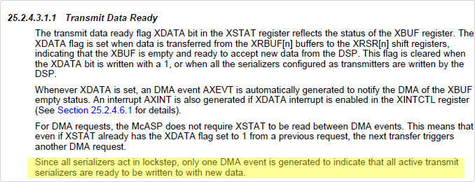
For transmit operations through the DMA port, the DMA/CPU should write to the same XBUF DMA port
address to service all of the active transmit serializers. In addition, the DMA/CPU should write to the XBUF
for all active transmit serializers in incremental (although not necessarily consecutive) order. For example,
if serializers 0, 4, 5, and 7 are set up as active transmitters, the DMA/CPU should write to the XBUF DMA
port address four times with data for serializers 0, 4, 5, and 7 upon each transmit data ready event. This
exact servicing order must be followed so that data appears in the appropriate serializers.
"

In my case I have serializers
MCASP->SRCTL8    = 0x000D; //  8 = xmit
MCASP->SRCTL9    = 0x000D; //  9 = xmit

i.e. 8 and 9 set as active transmit serializers.
So if my edma is set up correctly i.e
param.DST = mcasp_xmt0_register = DMA XBUF
BCNT| = 4
etc.
Should work,  yes?

Is there any thing I could be missing etc.  ether in setting up McASP and or the edma PaRAM set's ?
causing no events for xmt?

Thanks


  • Do you have AFIFO enabled?  Did you change the threshold to 4?

    EDIT: I think the threshold should be 2 if I understand what you're doing correctly, i.e. 2 receive channels and 2 transmit channels.

  • Am I setting up the AFIFO correctly and in the correct place?

    1. Reset McASP to default values by setting GBLCTL = 0.

    MCASP->GBLCTL  = 0; // Hold all in reset 

    2. (a) Write FIFO:  If the Write FIFO will be enabled, configure WFIFOCTL. Note that WFIFOCTL.WENA should
    not be set to 1 (enabled) until the other bitfields in this register are configured.

    MCASP_AFIOF_WFIFO->WFIFOCTL = 0x1001;   //  write WNUMEVT =16 WNUMDMA =1 to   0x01D01010  WFIFOCTL


    (b) Read FIFO:If the Read FIFO will be enabled, configure RFIFOCTL. Note that RFIFOCTL.RENA should not
    be set to 1 (enabled) until the other bitfields in this register are configured.

    MCASP_AFIOF_RFIFO->RFIFOCTL = 0x1001;    //  write RNUMEVT =16 RNUMDMA =1  to   0x01D01018  RFIFOCTL


    MCASP_AFIOF_WFIFO->WFIFOCTL = MCASP_AFIOF_WFIFO->WFIFOCTL | 0x10000;  WENA WFIFOCTL


    MCASP_AFIOF_RFIFO->RFIFOCTL = MCASP_AFIOF_RFIFO->RFIFOCTL | 0x10000;   RENA   RFIFOCTL

    3. Configure all McASP registers except GBLCTL in the following order: ... etc etc...

    MCASP->RMASK      = 0xFFFFFFFF;

    ..... etc... etc....

    Because it does not seem to work even with my no extra xmt D/A... Do I need to point the edma to a different buffer or?  I did not think so.

    NOTE:

    WNUMEVT and RNUMEVT  = 16 =  CCNT of edma = sample_count = SAMPLES_PER_BUF 16

    Thanks

  • Brian Flinn said:

    2. (a) Write FIFO:  If the Write FIFO will be enabled, configure WFIFOCTL. Note that WFIFOCTL.WENA should
    not be set to 1 (enabled) until the other bitfields in this register are configured.

    MCASP_AFIOF_WFIFO->WFIFOCTL = 0x1001;   //  write WNUMEVT =16 WNUMDMA =1 to   0x01D01010  WFIFOCTL


    (b) Read FIFO:If the Read FIFO will be enabled, configure RFIFOCTL. Note that RFIFOCTL.RENA should not
    be set to 1 (enabled) until the other bitfields in this register are configured.

    MCASP_AFIOF_RFIFO->RFIFOCTL = 0x1001;    //  write RNUMEVT =16 RNUMDMA =1  to   0x01D01018  RFIFOCTL


    MCASP_AFIOF_WFIFO->WFIFOCTL = MCASP_AFIOF_WFIFO->WFIFOCTL | 0x10000;  WENA WFIFOCTL

    Incorrect.  Read the WNUMDMA/RNUMDMA description in the TRM.

  • Brian Flinn said:
    param.OPT = (EDMA_XMT_PING_TCC << 12) | (1 << 20);      // transfer complete interrupt enabled

    You need an AB-sync transfer in order to use the FIFO.  Recall that 'CIDX is calculated different for AB-sync transfers so that will change too.

    Brian Flinn said:
    param.A_B_CNT = (num_channels << 16) | sample_size;                // actual format: BCNT|ACNT

    Your BCNT value that gets programmed here needs to match WNUMEVT/RNUMEVT in the AFIFO.

  • //                                                    SAMPLES_PER_BUF                                                 One xmit seriealsier
    //                                                                         |                                                                                    |
    MCASP_AFIOF_WFIFO->WFIFOCTL = ((16) << AFIFO_WFIFOCTL_WNUMEVT_SHIFT) | 1;

    //                                                    SAMPLES_PER_BUF                                                 one rcv serializer
    //                                                                       |                                                                                   |
    MCASP_AFIOF_RFIFO->RFIFOCTL = ((16) << AFIFO_RFIFOCTL_RNUMEVT_SHIFT) | 1;


    // -----------------------------------------------------------------------------------------

    MCASP_AFIOF_WFIFO->WFIFOCTL |= (AFIFO_WFIFOCTL_WENA_ENABLED << AFIFO_WFIFOCTL_WENA_SHIFT);
    MCASP_AFIOF_RFIFO->RFIFOCTL |= (AFIFO_RFIFOCTL_RENA_ENABLED << AFIFO_RFIFOCTL_RENA_SHIFT);

    Above correct now?  BCNT matches WNUMEVT  and RNUMEVT

    You need an AB-sync transfer in order to use the FIFO. 

    Where is that described ?

    What would the second dimension be ?  Lost me on AB-sync

    Recall that 'CIDX is calculated different for AB-sync transfers so that will change too.

    Need more guidance please !! I have not seen where AFIFO need different calculating and or AB-sync...

    Please point to the relevant sections or  help me further.

    Do you think the AFIFO is going to help my original problem of the added xmit seriealsier dma not working ?

    Thanks again

    Brian

  • Brian Flinn said:

    //                                                    SAMPLES_PER_BUF                                                 One xmit seriealsier
    //                                                                         |                                                                                    |
    MCASP_AFIOF_WFIFO->WFIFOCTL = ((16) << AFIFO_WFIFOCTL_WNUMEVT_SHIFT) | 1;

    //                                                    SAMPLES_PER_BUF                                                 one rcv serializer
    //                                                                       |                                                                                   |
    MCASP_AFIOF_RFIFO->RFIFOCTL = ((16) << AFIFO_RFIFOCTL_RNUMEVT_SHIFT) | 1;


    // -----------------------------------------------------------------------------------------

    MCASP_AFIOF_WFIFO->WFIFOCTL |= (AFIFO_WFIFOCTL_WENA_ENABLED << AFIFO_WFIFOCTL_WENA_SHIFT);
    MCASP_AFIOF_RFIFO->RFIFOCTL |= (AFIFO_RFIFOCTL_RENA_ENABLED << AFIFO_RFIFOCTL_RENA_SHIFT);

    Above correct now?  BCNT matches WNUMEVT  and RNUMEVT

    I don't understand your change -- the McASP AFIFO was already configured for WNUMEVT=16, i.e. it doesn't appear you actually changed anything.  The issue I pointed out was in the BCNT of your EDMA code.  You were setting BCNT=num_channels (looked like 4 from your comments).

    From what I can gather you have 2 transmit serializers and 2 receive serializers.  Right? 

    • You must set WNUMDMA=2 and RNUMDMA=2, i.e. must match the number of serializers.
    • WNUMEVT/RNUMEVT must be a multiple of WNUMDMA/RNUMDMA.  Looks like you've chosen 16, which is fine.
    • For the EDMA you must set ACNT=4 (FIFO width) and BCNT=16 (WNUMEVT/RNUMEVT), with AB-sync transfer type.  This requirement comes from the event pacer logic of the AFIFO.  See Sections 25.2.4.4.1.1 "Transmit DMA Event Pacer" and 25.2.4.4.2.1 "Receive DMA Event Pacer" for more details.
    • The 'CIDX for AB-sync transfers is calculated different than for A-sync transfers.  This is described in Section 18.2.2.2 "AB-Synchronized Transfers".
  • Brad Can you check my numbers and setup below this is just for xmit only.  Lets just stick with one xmit and one rec seriealsier for now, but to answer you're question there will be one stereo (2 ch) reciever I.e. A/D and two transmiter2 i.e. 2 (stereo) D/A's on seperate seriealsier's, so ultimately 1 rec seriealsier and 2 xmit seriealsier.

    NOTE: As mentioned I do have edma working with one xmit and one rec seriealsier, without AFIFO.

    When I added the second xmit seriealsier  I could not get it to work... hence I guess the reason we are looking at AFIFO... although in reality I can not tolerate any additional latency the AFIFO may add.... so...

    But for now to get AFIFO working (as you suggested to try to ultematly get the second xmit seriealsier working) I am simply going back to the one xmit and one rec seriealsier case and I cant seem to get it right ... could you take a look at just the xmit side below and check me out... ?  The rec. should be similar only changing source and dst... etc....


    Thanks again

    xmit
          PING L 0..8 |  PONG L 0..8  |  PING R 0..8 |  PONG R 0..8 |     buffers[8] each ping_l pong_l ping_r pong_l
          32 bit             |  32 bit             |  32 bit             |  32 bit              |
          |                      |  |                      |                         |  |                        |
          XXXXXXXX    |  XXXXXXXX     |   XXXXXXXX   |  XXXXXXXX      |
       0 ||                   32                       64||                  96                        OFFSET                  
          ||                                                   ||             
          ||                                                   ||            
          ||--|                                               ||
          |   |                                                ||   <... repeat for all 16   
          |   |                                                ||
          |   |                                                ||
          Z|Z|Z|Z|Z|Z|Z|Z|Z|Z|Z|Z|Z|Z|Z|Z ||   -- AFIFO WNUMEVT=16  16 -32 bit locations
            |   |-----------------------------------||
            |                                                    |
            |---------------------------------------|

    //  this is with AB-sync
    // 1. setup channel PaRAM slot
    OPT  (EDMA_XMT_PING_TCC << 12) | (1 << 20) | (1 << 2);  //AB-sync; //transfer complete interrupt enabled

    SRC  @PING L  see above

    BCNT 16  ACINT 4

    DST 0x01D02000  (DMA XBUF)   although AFIFO actually

    DSTBIDX  0    SRCBIDX 64    

    BCNTRLD 16    LINK =EDMA_XMTPONG

    DSTCIDX  4    SRCCIDX 4

    CCNT 1   <-------  ? transfering all 64 bits at once with AFIFO
    -----------------------------------------------------------------
    edmaWritePaRAM(EDMA_MCASPTXCH, &param); // save above to param slot
    -----------------------------------------------------------------
    // 2. setup ping PaRAM set (to be reloaded later)
        edmaWritePaRAM(EDMA_XMTPING, &param); // save above to param slot
    ------------------------------------------------------------------
     // 3. setup pong PaRAM set (to be loaded and reloaded later)
    OPT  (EDMA_XMT_PONG_TCC<< 12) | (1 << 20) | (1 << 2);  //AB-sync; //transfer complete interrupt enabled

    DSTBIDX  0    SRCBIDX 64
       
    BCNTRLD 16    LINK =EDMA_XMTPING

    DSTCIDX  4    SRCCIDX 4

    SRC @PONG L see above

    edmaWritePaRAM(EDMA_XMTPONG, &param); // save above to param slot

  • So it looks like you're also using the EDMA to interleave/deinterleave the data.  That will impose additional constraints.

    Your above parameters are not correct.  In particular you have the SRCBIDX=64.  The first element transferred will be 32-bits from pingL.  Then you'll index 64 bytes and your second element transferred will be 32-bits from pingR (that much is correct).  However, it will then continue jumping forward 64 bytes at a time until it has done 16 transfers (BCNT).  So the first 2 transfers were right but the remaining 14 are all grabbing random data from memory!

    Long story short, your interleaving of data will require that you configure BCNT=2, which matches the number of channels you're interleaving.  If you wish to output on 2 serializers your data will need to be arranged in memory as follows:

    • pingL1
    • pingL2
    • pingR1
    • pingR2
    • pongL1
    • pongL2
    • pongR1
    • pongR2

    Continuing... Now that you change BCNT=2 you will correspondingly need to change WNUMEVT=2 and CCNT=8.  Your DSTCIDX should be zero since your destination is the AFIFO.

  • BTW This is not my code nor architecture... It it TI's code see first thread message above.
    It has been modified to work on our hardware. 
    And It does work with no AFIFO and ONE input A/D on one seriealsier, and ONE D/A on another seriealsier.
    But it does not work when I add a 2nd D/A on another transmit seriealsier...

    So, your suggestion was to turn on the AFIFO and see if that helps.
     
    Lets juts try to get AFIFO working and keep this as simple as possible then..
    I.E.  ONE input A/D on one seriliser, and ONE D/A on another serieliser WITH AFIFO turnd on.

    So I will first off rearrange the 8 each ping pong buffers as follows... Again lets forget about the second transmit D/A for now...

    pingL[0..7]
    pingR[0..7]
    pongL[0..7]
    pongR[0..7]


    Ok so far?

    make AFIFO a single L/R buffer I.E. WNUMEVT=2  OK?
    AB-sync on OK?

    Lets just talk about xmit side first, and just concentrate on the ping first.... OK?

    SRC will be  @pingL

    BCNT 2  ACINT 4

    DST will be 0x01D02000  (DMA XBUF) although AFIFO actually

    DISTBIDX  4  <---- when ACINT 0 index the detestation by this much correct ?
    DSTCIDX   0  <---- when BCNT 0 index the detestation by this much  correct ?

    SRCBIDX   4 * 8   <---- 4 bites each * the number of buffers / buffer i.e.
                            when ACNT = 0 and BCNT decrements move to this source location i.e. move to pingR[x]
                            (relative to the first element for AB sinc) correct?
                           
    SRCCIDX  4 * -7   <----- 4 bites each * the number of elements we need to go back to the second element in pingL[x+1]
                            when BCNT = 0 move to this source location
                            (relative to the first element for AB sinc) correct?
                           
    CCNT = 8   <---- 8 buffers each do it 8 times.... correct...?

    Please check me hear...  Thanks

    Again, I hope this is not a exercise for not, because I can not tolerate any more latency then necessary.  OK ?

    Thanks again Brad for your' patients and help.... Brian !

  • Brian Flinn said:
    Again, I hope this is not a exercise for not, because I can not tolerate any more latency then necessary.  OK ?

    Let's forget the FIFO then.  On the receive side the FIFO would not be a problem because you can set RNUMEVT=1 and grab data as soon as it's available.  On the transmit side, even if you set WNUMEVT=1, it's going to keep sending EDMA events over and over again.  I think it's going to cause issues for you given your small buffer size and low latency.

    I think a lot of what you're doing here is still useful for the case of no FIFO and servicing multiple channels.  In particular, you will need to be AB-synchronized in order to send multiple samples per sync event, i.e. you will need to send 1 sample per serializer.  So I think the direction you're headed is correct.

    Your SRCCIDX above is incorrect for AB-sync transfer.  It should be 4.

  • AB-sinc So SRCCIDX is always referenced to where the begining of the source is first time around
    Then SRCBIDX will us the updated offset from SRCCIDX for its offset when needed correct ?

    Should I still rerange the buffers ?

    > I think it's going to cause issues for you given your small buffer size and low latency.

    Should I be concerned,  I gota get this working.....

    Any more tips suggestions are welcome... This is only the tip of the iceburg as on next products there will probably be as many transmit and rec
    seriealsier as we can get...   

  • What have you already gotten working?  Do you have 2 transmit serializers working with interrupts?

    Brian Flinn said:
    AB-sinc So SRCCIDX is always referenced to where the begining of the source is first time around
    Then SRCBIDX will us the updated offset from SRCCIDX for its offset when needed correct ?

    CIDX is measured from the beginning of the frame in an AB-sync transfer as discussed in 18.2.2.2 "AB-Synchronized Transfers".

    Brian Flinn said:
    Should I still rerange the buffers ?

    The buffers need to be arranged in the same order as you wish to send samples to the McASP.

    Brian Flinn said:
    > I think it's going to cause issues for you given your small buffer size and low latency.

    Should I be concerned,  I gota get this working.....

    "It" was the FIFO.  So, no, you should not be concerned.

  • I have one receiver and one transmitter working with edma...

    I have one receiver and one transmitter working with polling and

    I have one receiver and two transmitters working with polling

    i.e.

       for(;;){

                 // wait for xmit ready and send a sample ch 0
                while (!CHKBIT(MCASP->SRCTL8, XRDY)) {}
                MCASP->XBUF8 = dat;

                // wait for xmit ready and send a sample. ch 0
                while (!CHKBIT(MCASP->SRCTL9, XRDY)) {}
                MCASP->XBUF9 = dat;

                dat = MCASP->XBUF0;

                  // wait for xmit ready and send a sample. ch 1
                while (!CHKBIT(MCASP->SRCTL8, XRDY)) {}
                MCASP->XBUF8 = dat;

                // wait for xmit ready and send a sample. ch 1
                while (!CHKBIT(MCASP->SRCTL9, XRDY)) {}
                MCASP->XBUF9 = dat;

                dat = MCASP->XBUF0;

    }

    Did not try the interrupt case, I was hopping to use edma directly.

    I will rerange buffers then

    pingL1

    pingR1

    pingL2

    pingR2

    pongL1

    pongR1

    pongL2

    pongR2

  • Ah, your code that polls is writing to the config port rather than the DMA port.  That code won't work on the DMA port. When writing to the McASP the order should be <serializer 0, slot n>, <serializer 1, slot n>, <serializer 0, slot n+1>, <serializer 1, slot n+1>, etc.  In other words, when you get the McASP event you would write your data for "slot n" to ALL of your serializers (e.g. write "left" to serializers 1 and 2).  When you get the next event you would write "slot n+1" to ALL serializers, e.g. write "right" to serializers 1 and 2.

  • That is correct and that is what I am doing in my code as is now, and it does not work ...

    Please, re-read, if possible, the original start of this thread that explains the changes to the TI source.... and what I see..

    I should have mentioned the one rec and one transmit case edma that works I tried  it both ways.

    I.E.

    using the configuration port at  MCASP_REG_BASE + 0x0220  //mcasp->XBUF8  with McASP XFMT  RBUSEL = 1 and MCASP_REG_BASE + 0x0280); // mcasp->RBUF0 rec on 0 with McASP RFMT  RBUSEL = 1

    as well as the DMA port MCASP_REG_BASE + 0x2000); // DMA XBUF with McASP XFMT  RBUSEL = 0 and MCASP_REG_BASE + 0x2000); // DMA RBUF with McASP RFMT  RBUSEL = 0

    Both work for one in one out serializer.

    Please see first message in the thread..... Thanks

    Brian


  • Just dump your registers for McASP and EDMA.  I don't want to look at code.

  • Can not really help there to much I'm stuck in  the dark ages with CCS 3.3 you would have to decode them from memory locations.... 

    What would you like for me to do then?

    Thanks Brian

  • Just post your buffer arrangement and your EDMA parameter set like you did in this post.

  • Brad

    #define BUF_LENGTH 16

    rcv_ping_ch1[BUF_LENGTH]
    rcv_pong_ch1[BUF_LENGTH]
    rcv_ping_ch2[BUF_LENGTH]
    rcv_pong_ch2[BUF_LENGTH]
    xmt_ping_ch1[BUF_LENGTH]
    xmt_pong_ch1[BUF_LENGTH]
    xmt_ping_ch2[BUF_LENGTH]
    xmt_pong_ch2[BUF_LENGTH]
    xmt_ping_ch3[BUF_LENGTH]
    xmt_pong_ch3[BUF_LENGTH]
    xmt_ping_ch4[BUF_LENGTH]
    xmt_pong_ch4[BUF_LENGTH];

    NO AFIFO
    NO AB-sync

    SRC will be  &xmt_ping_ch1

    BCNT 4  ACINT 4

    DST will be 0x01D02000  (DMA XBUF) NO AFIFO

    DISTBIDX  0
    DSTCIDX   0  

    SRCBIDX   4 * 16 * 2   = 128  get to next xmt_ping  NO AB-sinc
                           
    SRCCIDX  -124    no AB sinc
                           
    CCNT = 16   <---- 16 buffers each do it 16 times

    Brian


  • Close.  Enable AB-sync and adjust your SRCCIDX accordingly.

  • NO AFIFO
    AB-sync

    SRC will be  &xmt_ping_ch1

    BCNT 4  ACINT 4

    DST will be 0x01D02000  (DMA XBUF) NO AFIFO

    DISTBIDX  0
    DSTCIDX   0  

    SRCBIDX   4 * 16 * 2   = 128  get to next xmt_ping  NO AB-sinc
                           
    SRCCIDX  4   AB sinc
                           
    CCNT = 16   <---- 16 buffers each do it 16 times 

    I NOW HAVE XMIT EVENTS !!!!  

    However my rec may be a issue now ?  see  

    Do you think I need AB-sinc on rec.....?   We're getting there !!! Thanks

  • When I engage AB-sync on the reciever

    I have no data in the ch2 locations i.e rec_ping_ch2 rec_pong_ch2

    rec edma settings

    NO AFIFO
    AB-sync

    SRC will be  e 0x01D02000  (DMA XBUF) NO AFIFO &xmt_ping_ch1

    BCNT 2  ACINT 4

    DST &rec_ping_ch1

    DISTBIDX  128
    DSTCIDX   4

    SRCBIDX   4
                           
    SRCCIDX  0  AB sinc
                           
    CCNT = 16   <---- 16 buffers each do it 16 times

    Thoughts ?

  • I'm looking again at your buffer layout.  I think I misunderstood things.  Each serializer contains TWO channels (left and right) correct? When I read your last post I was considering each serializer to be a channel, rather than 2 channels per serializer.  That being the case, you still have things setup incorrectly.  If you have 2 serializers then you must configure BCNT=2.

    You have defined channels 1-4, but I'm not entirely clear on the mapping of serializers to channels.  For example, is this what you're trying to do:

    • Channel 1 = Serializer 1, Left
    • Channel 2 = Serializer 1, Right
    • Channel 3 = Serializer 2, Left
    • Channel 4 = Serializer 2, Right

    I'll go with that assumption for now.  Let's try to visualize this.  In fact, after having gone through this exercise I think we'll need to do things differently in order to have multiple serializers AND do the interleaving/deinterleaving.

    Here's how your data will come into the device:

    Serializer 1: L1| R1| L2| R2| L3| R3| ... L8| R8|

    Serializer 2: L1| R1| L2| R2| L3| R3| ... L8| R8|

    EDMA Events:    A   B   C   D   E   F ...   O   P

    Now here's the viewpoint of the EDMA, i.e. what data it needs to move for each event:

    A: L1, L1

    B: R1, R1

    C: L2, L2

    D: R2, R2

    E: L3, L3

    F: R3, R3

    :

    O: L8, L8

    P: R8, R8

    Finally, here's the buffers in memory where we actually write the data.

    chan1[8] = {L1, L2, L3, ..., L8}

    chan2[8] = {R1, R2, R3, ..., R8}

    chan3[8] = {L1, L2, L3, ..., L8}

    chan4[8] = {R1, R2, R3, ..., R8}

    Does this all make sense?  Is that what you're trying to do?  Hopefully the color coding makes it a little easier to visualize.  I'm going to pause here to make sure we're both on the same page.  I've got a plan so you can get this all done with EDMA, but we'll need to use chaining to make it happen.

    Brad

  • NO.

    One serializers i.e. (One A/D on one AUX McASP port )on rec. side McASP that recieves (stereo) i.e left, right data,

    I call rec_ping_ / or pong ch1 and rec_ping_ / pong ch2

    this is the rec side

    ----

    Two serializers (2 D/A phyiscal devices connected to 2 different AUX McASP ports), on the xmit side McASP that I send (stero) ie. left, right data

    I call xmit_ping / pong ch 1 and xmit_ping_ / pong ch2, and to the second serialiser xmit_ping_ / pong ch 3 and xmit_ping_ pong ch4...

    this is the xmit side

    -----

    I think it is a rec side problem now because xmit  is working if I copy rec. data from
    rcv_ping_ch1 to xmt_ping_ch1   (left in from rec serialiser --- to transmit serialiser  1 D/A 1 LEFT)
    rcv_ping_ch1 to xmt_ping_ch2    (left in from  rec serialiser  --- to transmit serialiser 1 D/A 1 RIGHT)
    rcv_ping_ch1 to xmt_ping_ch3   (left in from  rec serialiser  --- to transmit serialiser 2 D/A 1 LEFT)
    rcv_ping_ch1 to xmt_ping_ch4   (left in from  rec serialiser  --- to transmit serialiser 2 D/A 1 RIGHT)

    instead of  (what I want and need to do)...
    rcv_ping_ch1 to xmt_ping_ch1 (left in from rec serialiser --- to transmit serialiser  1 D/A 1 LEFT)
    rcv_ping_ch2 to xmt_ping_ch2 (right in from rec serialiser --- to transmit serialiser  1 D/A 1 RIGHT)
    rcv_ping_ch1 to xmt_ping_ch3 (left in from rec serialiser --- to transmit serialiser  1 D/A 1 LEFT)
    rcv_ping_ch2 to xmt_ping_ch4 (right  in from rec serialiser --- to transmit serialiser  1 D/A 1 RIGHT)

    I.e there is no rec data in the right or rec channel (rec ch2) ping or pong with AB-sinc on...
    As mentioned there is no data in the rcv ch2 ping or pong... with AB-sync...

    I do not want to use e2e as a personal request / sounding board,  but perhaps you can look at the last e-mail I sent to you ....


    Thanks Again Brian

  • FYI, the color-coded drawing from my previous post was showing the transmit side only.  I wasn't sure what your "NO" applied to.  As far as I can tell your description of the buffers is the same as what I showed.  Can you specify what's wrong so we're both on the same page?

    In terms of the receive side, it's likely messed up too. Please post your EDMA parameters for the receive side.

    I'm positive your transmit side is messed up as well.  As a quick experiment, comment out the copies of rcv_1 to xmt1/2.  In other words, don't ever write to xmt_1/2.  Only copy data to xmt_3/4.  I bet it keeps on working exactly the same way...  That's because it is REQUIRED to make the number of writes to the McASP equal to the number of serializers.  You have 2 transmit serializers and should only be doing 2 writes.  When performing 4 writes the subsequent writes will end up over-writing what you already put there, i.e. the data from xmt_1/2 in your case will be meaningless because it will be overwritten by xmt_3/4.

  • Brad

    Wanted to mention that the color-coded drawing is correct for the xmit side.

    >Does this all make sense? YES.

    Is that what you're trying to do? YES.

    Hopefully the color coding makes it a little easier to visualize. YES.

    I'm going to pause here to make sure we're both on the same page. I've got a plan so you can get this all done with EDMA, but we'll need to use chaining to make it happen.

    If indeed

    >That's because it is REQUIRED to make the number of writes to the McASP equal to the number of serializers.  You have 2 transmit serializers and should only be doing 2 writes, and

    >If you have 2 serializers then you must configure BCNT=2.

    If this Is correct that BCNT must = the number of serializers then I don’t think my current method is going to work to do the L / R sort on ether rec. side or transmit side. Because on ether side I need to ether put or get the L / R data in to / from separate buffers... I also have no idea (if BCNT must = the number of serializers) how the original TI code from hear http://software-dl.ti.com/dsps/dsps_public_sw/c6000/web/c6747_audio_edma_app/latest/index_FDS.html worked? As there is only one rec serializer / one xmit serializer and BCNT =2, .... as well, I was hoping to use from this document http://processors.wiki.ti.com/index.php?title=File:EDMA3_LLD.pdf&limit=20 starting on page 38 Channel sorting. I am guessing there is only one serializer involved hear like the example code above, and AB sync in not on. What am I missing hear ? >If you have 2 serializers then you must configure BCNT=2? I assume the same holds then for 1 serializers then you must configure BCNT=1 Yes?

    Then how does the Channel sorting work in the above document, and or how to make it work on my system ? Thanks Brian.

  • Ok, sounds like we're on the same page.  Good!

    Brian Flinn said:

    I assume the same holds then for 1 serializers then you must configure BCNT=1 Yes?

    Then how does the Channel sorting work in the above document, and or how to make it work on my system ? Thanks Brian.

    The overriding principle here is that when you get the DMA event from the McASP you need to service all the active serializers.  So in the case of a single serializer you would do one write and in the case of n serializers you would do n writes.

    The case where you have only one serializer is unique because you can simply do an A-sync transfer with ACNT=4.  In this case BCNT is a "don't care" in terms of servicing the serializers and hence you can do your interleaving my taking advantage of BCNT and the indexes.

    If we look at the general case of n serializers where n>=2 then you would need the following setup:

    • AB-sync transfer
    • ACNT=4
    • BCNT=n
    • SRCBIDX = number of bytes between the arrays corresponding to each serializer

    This is the case that you have.  So as you can see the BCNT is already tied to number of serializers and BIDX is tied to the space between arrays.  Normally you would do the channel sorting with the BIDX and CIDX, but now BIDX is not available for this purpose!  In other words, we need to modify the way we do it.

    There are a few different solutions to the issue.  I'm trying to decide which way would be the best.  I'll go ahead and post this for now to make sure you understand the underlying issue.

  • PS.  It's also worth noting (for others) that part of the complication here is the fact that you are very latency sensitive and cannot use the FIFO.  For more typical applications you would enable the FIFO and set WNUMEVT equal to the number of serializers.  In this manner the FIFO itself would handle the process of sending data to each active serializer.  This would more or less decouple you from this restriction.

  • There's a lot of ways you could do this, but I think I like this method the best.

    Solution: Use one EDMA channel per serializer

    This solution ignores the fact that multiple channels exist.  Here are the few modifications:

    For channels 1 - "n-1":

    • ITCCHEN=1
    • TCCHEN=1
    • TCC = "next channel"
    • A-sync
    • Early completion

    For channel n:

    • ITCCHEN=0
    • TCCHEN=0
    • TCC = interrupt bit in IPR that you will look for
    • A-sync
    • Normal completion

    Let's use your case of 2 transmit serializers.  So in this case the McASP DMA event would cause a channel to run as usual.  That channel would transfer a single data element (e.g. A-sync transfer).  Of course, we are required to transfer 2 elements since we have 2 serializers.  To accomplish this, we chain to a second channel which also transfers a single element.  In this way we have transferred our required number of samples but now we can do indexing the way we did in the single-serializer case.

  • I see where you are heading with the chaining, however, I believe this is going to be more complex because I am already chaining the ping / pong / interrupt......but lets hold that for the moment.

    Lets try to simplify this.

    Could this make it simpler for the xmt for now ?...

    I sorted the L/R data to not be separate arrays, of just left and just right data … so it looks like this.. for transmit.

    Chan1_2_3_4 xmt buffer[8*4] = {L1, R1, L1,R1,L2, R2, L2,R2,... } etc.

    Could this work?

    Wouldn't BCNT have to be 4 ?

    Does it have to be AB sync?

    Can you help me out with the parameters if the data arrange like this would work?

    I need to do whatever it takes to “simplify” this for now!  Thanks...

  • Brian Flinn said:
    I see where you are heading with the chaining, however, I believe this is going to be more complex because I am already chaining the ping / pong / interrupt......but lets hold that for the moment.

    You are linking the ping and pong.  That is independent of chaining.

    Brian Flinn said:

    Could this make it simpler for the xmt for now ?...

    I sorted the L/R data to not be separate arrays, of just left and just right data … so it looks like this.. for transmit.

    Chan1_2_3_4 xmt buffer[8*4] = {L1, R1, L1,R1,L2, R2, L2,R2,... } etc.

    Could this work?

    Wouldn't BCNT have to be 4 ?

    Does it have to be AB sync?

    Can you help me out with the parameters if the data arrange like this would work?

    This will tremendously simplify things.  Probably a good idea...  However, your order is wrong.  It should be:

    Chan1_2_3_4 xmt buffer[8*4] = {L1, L1,R1, R1,L2, L2, R2, R2,... }

    BCNT is still 2... Regardless of your buffer arrangement each serializer receives one sample at a time, so you must always transfer 1 sample/serializer for each DMA event.

    • AB-sync
    • ACNT=4
    • BCNT=2
    • CCNT=8
    • SRCBIDX=4 (ACNT for contiguous data)
    • DSTBIDX=0
    • SRCCIDX=8 (ACNT*BCNT for contiguous data in AB-sync transfer)
    • DSTCIDX=0

    So if you move to 3 serializers you just make BCNT=3 and SRCCIDX=12...

  • AB-sync param.OPT = (EDMA_XMT_PING_TCC << 12) | (1 << 20) | (1 << 2);

    BCNT 2

    ACNT 4

    DSTBIDX 0

    SCRBIDX 4

    BCNTRLD 2

    DSTCIDX 0

    SRCCIDX 8

    CCNT 48

    A 48 point sign wave (from a table) put into all L and R channels in order to not include the receiver for now. Dump of Chan1_2_3_4 xmt buffer[ [48 * 4] in 32 bit signed integer

    0

    0

    0

    0

    140115968

    140115968

    140115968

    140115968

    277872640

    277872640

    277872640

    277872640

    410877952

    410877952

    410877952

    410877952

    536838144

    536838144

    536838144

    536838144

    653590528

    653590528

    653590528

    653590528

    759201792

    759201792

    759201792

    759201792

    851804160

    851804160

    851804160

    851804160

    929824768

    929824768

    929824768

    929824768

    991920128

    991920128

    991920128

    991920128

    1037074432

    1037074432

    1037074432

    1037074432

    1064468480

    1064468480

    1064468480

    1064468480

    1073643520

    1073643520

    1073643520

    1073643520

    1064468480

    1064468480

    1064468480

    1064468480

    1037074432

    1037074432

    1037074432

    1037074432

    997687296

    997687296

    997687296

    997687296

    929824768

    929824768

    929824768

    929824768

    851804160

    851804160

    851804160

    851804160

    759201792

    759201792

    759201792

    759201792

    653590528

    653590528

    653590528

    653590528

    536838144

    536838144

    536838144

    536838144

    410877952

    410877952

    410877952

    410877952

    277872640

    277872640

    277872640

    277872640

    140115968

    140115968

    140115968

    140115968

    0

    0

    0

    0

    -140115968

    -140115968

    -140115968

    -140115968

    -277872640

    -277872640

    -277872640

    -277872640

    -410845184

    -410845184

    -410845184

    -410845184

    -536805376

    -536805376

    -536805376

    -536805376

    -653590528

    -653590528

    -653590528

    -653590528

    -759201792

    -759201792

    -759201792

    -759201792

    -851804160

    -851804160

    -851804160

    -851804160

    -929824768

    -929824768

    -929824768

    -929824768

    -991920128

    -991920128

    -991920128

    -991920128

    -1037074432

    -1037074432

    -1037074432

    -1037074432

    -1064468480

    -1064468480

    -1064468480

    -1064468480

    -1073676288

    -1073676288

    -1073676288

    -1073676288

    -1064468480

    -1064468480

    -1064468480

    -1064468480

    -1037074432

    -1037074432

    -1037074432

    -1037074432

    -991920128

    -991920128

    -991920128

    -991920128

    -929824768

    -929824768

    -929824768

    -929824768

    -851771392

    -851771392

    -851771392

    -851771392

    -759201792

    -759201792

    -759201792

    -759201792

    -653590528

    -653590528

    -653590528

    -653590528

    -536805376

    -536805376

    -536805376

    -536805376

    -410845184

    -410845184

    -410845184

    -410845184

    -277872640

    -277872640

    -277872640

    -277872640

    -140115968

    -140115968

    -140115968

    -140115968

    A look at the output ?

  • Have you tested that lookup table previously?  Is it supposed to be left justified?  Is it supposed to be signed?  How did you implement the linking?  Did you link to a copy of the exact parameters?

  • Have you tested that lookup table previously? YES, Used / use it often.

    Is it supposed to be left justified?  YES.

    Is it supposed to be signed?  YES.

    How did you implement the linking? 

    It is very similar to the reference code.  I know you hate to read code, but hear goes.

    #define EDMA_MCASPTXCH       1   // EDMA channel for McASP0 TX
    #define EDMA_MCASPRXCH       0   // EDMA channel for McASP0 RX
    #endif

    #define EDMA_XMTPING         32
    #define EDMA_XMTPONG         33
    #define EDMA_RCVPING         34
    #define EDMA_RCVPONG         35

    #define EDMA_RCV_PING_TCC    1
    #define EDMA_RCV_PONG_TCC    2
    #define EDMA_XMT_PING_TCC    3
    #define EDMA_XMT_PONG_TCC    4

    ---------------------------------------------------------------------------------------------------------------------------------

    void *mcasp_xmt0_register = (void *)(MCASP_REG_BASE + 0x2000);   // DMA XBUF

    #define SAMPLES_PER_BUF     48

    #define BUF_LENGTH          SAMPLES_PER_BUF

    volatile Uint32  xmt_ping_ch1_2_3_4[BUF_LENGTH *4],
                                xmt_pong_ch1_2_3_4[BUF_LENGTH *4];


    void setup_edma_pingpong_xmt(void *src_ping      //<-------------- xmt_ping_ch1_2_3_4

                                                                  void *src_pong   //<---------------xmt_pong_ch1_2_3_4

                                                                  void *dst,   //<------------ mcasp_xmt0_register
                                                                  Uint32 sample_count )   //<---------------SAMPLES_PER_BUF
    {
        CSL_Edma3ccParamSetRegs param;
     

        // 1. setup channel PaRAM slot
        param.OPT = (EDMA_XMT_PING_TCC << 12) | (1 << 20) | (1 << 2);      // transfer complete interrupt enabled AB-sync 
        param.SRC = (Uint32)src_ping
        param.A_B_CNT = (2 << 16) | 4;                                                                      // actual format: BCNT|ACNT
        param.DST = (Uint32)dst;
        param.SRC_DST_BIDX = (0 << 16) | 4;                                                           // actual format: DSTBIDX|SCRBIDX

        param.LINK_BCNTRLD = (2  << 16) | (EDMA_XMTPONG * 0x20);             // actual format: BCNTRLD|LINK
        param.SRC_DST_CIDX = (0 << 16) | (8 & 0x0000FFFF);                            // actual format: DSTCIDX|SRCCIDX
        param.CCNT = sample_count;
        edmaWritePaRAM(EDMA_MCASPTXCH, &param);

        // 2. setup ping PaRAM set (to be reloaded later)
        edmaWritePaRAM(EDMA_XMTPING, &param);

        // 3. setup pong PaRAM set (to be loaded and reloaded later)
        param.OPT = (EDMA_XMT_PONG_TCC << 12) | (1 << 20) | (1 << 2);      // transfer complete interrupt enabled    AB-sync
       
        param.SRC_DST_BIDX = (0 << 16) | 4;                                                        // actual format: DSTBIDX|SCRBIDX

        param.LINK_BCNTRLD = (2 << 16) | (EDMA_XMTPING * 0x20);           // actual format: BCNTRLD|LINK
        param.SRC_DST_CIDX = (0 << 16) | (8 & 0x0000FFFF);                        // actual format: DSTCIDX|SRCCIDX  
        param.SRC = (Uint32)src_pong;
        edmaWritePaRAM(EDMA_XMTPONG, &param);

    }
    --------------------------------------------------------------------------------------------------------------------
    void edmaWritePaRAM(Int ParamNum, CSL_Edma3ccParamSetRegs *ptrParamInfo)
    {
        edmaCcRegs->PARAMSET[ParamNum].OPT = ptrParamInfo->OPT;
        edmaCcRegs->PARAMSET[ParamNum].SRC = ptrParamInfo->SRC;
        edmaCcRegs->PARAMSET[ParamNum].A_B_CNT = ptrParamInfo->A_B_CNT;
        edmaCcRegs->PARAMSET[ParamNum].DST = ptrParamInfo->DST;
        edmaCcRegs->PARAMSET[ParamNum].SRC_DST_BIDX = ptrParamInfo->SRC_DST_BIDX;
        edmaCcRegs->PARAMSET[ParamNum].LINK_BCNTRLD = ptrParamInfo->LINK_BCNTRLD;
        edmaCcRegs->PARAMSET[ParamNum].SRC_DST_CIDX = ptrParamInfo->SRC_DST_CIDX;
        edmaCcRegs->PARAMSET[ParamNum].CCNT = ptrParamInfo->CCNT;
    }

    Did you link to a copy of the exact parameters?  I think so see above ?

    Thanks

  • The total size of an EDMA transfer in bytes is given by ACNT*BCNT*CCNT.  So in your case I expect to transfer 4*2*48=384 bytes.  Your buffer however is 4*48*4=768 bytes.  You're only transferring half of the buffer, which is clear from your output.  I messed up my earlier post when I made CCNT=8 (going with our earlier example of 8 samples in the buffer).  That should have been 16.

  • Lets stick with this sign wave test case for now. 

    Confused ?

    The total size of an EDMA transfer in bytes is given by ACNT*BCNT*CCNT 

    Your buffer however is 4*48*4                                              |           |            |

                                                                                                      4          48         4

    I thought BCNT "MUST MATCH" the number of serializers  

    i.e. >"If you have 2 serializers then you must configure BCNT=2"

    So in the case of this sign wave test it should be  ACNT  4 BCNT 48  CCNT 4 or ???? 

    ---------------------------------------------------------------------------------------------------------------------------

    In the other case of havingChan1_2_3_4 xmt buffer[8*4] = {L1, L1,R1, R1,L2, L2, R2, R2,... }

    You're saying

    ACNT 4

    BCNT 2

    CCNT 16

    correct ?

  • Brian Flinn said:

    The total size of an EDMA transfer in bytes is given by ACNT*BCNT*CCNT 

    Your buffer however is 4*48*4                                              |           |            |

                                                                                                      4          48         4

    I thought BCNT "MUST MATCH" the number of serializers  

    Yes, BCNT must match the number of serializers.  You're drawing conclusions that don't exist.  My calculation of your buffer size came from your definition:

    xmt buffer[ 48 * 4]

    Since you have 32-bit data that gave me the initial 4 and then I multiplied by the size 48*4.

    Brian Flinn said:

    In the other case of havingChan1_2_3_4 xmt buffer[8*4] = {L1, L1,R1, R1,L2, L2, R2, R2,... }

    You're saying

    ACNT 4

    BCNT 2

    CCNT 16

    correct ?

    Correct.  For your code all you need to do is make CCNT=96 and it will work.

  • THANKS BRAD !!!!! 

    Sign wave look up works as well as AUDIO REC. to AUDIO XMT   !!! ALL GOOD !!!

    ----------------------------

    I need to / must "eventually" get the chaining and linking working, because a manual channel sort will be “to much wasted overhead” in our very “large” channel count systems to come on this platform.

    I would like to hear you're,

    >”There are a few different solutions to the issue.  I'm trying to decide which way would be the best.”,

    other idea's on this?

    (As well as “others” who may have been monitoring this thread) etc.

    Thanks again Brad !!

    --------------------------------

    I guess ,If you like, you can close this out, but again would like to hear your input on “different solutions” to make this “scalable / expandable, using the chaining and linking etc Your call on if you or I should start a “new” thread on that.... Thanks


  • Yes, there are a lot of ways to slice the issue:

    1. Use one parameter set per serializer and chain them together.
    2. Use one parameter set per sample in your buffer and link them together.
    3. Deinterleave after the fact by chaining to a second parameter set that does the deinterleaving for you in one shot and then generates the interrupt.

    I don't think I want to go into great detail on each solution.  Solution 1 is what I already suggested.  Solution 3 would probably be the easiest to implement, i.e. you would just take what you already have working and you would set TCCHEN=1 such that when the buffer is full the EDMA would kick off another transfer to deinterleave the data.  That will delay the interrupt a bit though.

  • Hi Brad and Brian,

    I am using McASP port in OMAPL138 to transmit 24-bit data to 2 DACs (PCM1753) on AXR8 and AXR15. I am using CCS Version: 5.4.0.00091, and it is NON-OS development.

    I have successfully tested data transmission on both serializers using both CPU polling and CPU interrupt for McASP. For our timing needs I need to use McASP FIFO DMA transfers. It is very similar to what Brian is doing/has done.

    I read your posts on this forum and decide to follow the same. But for some reason I don’t see any data out of DAC. I am using the same configuration and same data.

    It would be of great help if Brian can share his source code as he got this working. I am setting WNUMEVT and WNUMDMA fields to 2 in WFIFOCTL register which I was not sure of.

    Please advise.

    Thanks a lot,

    Prathibha