This thread has been locked.

If you have a related question, please click the "Ask a related question" button in the top right corner. The newly created question will be automatically linked to this question.

AM6442: Flash open fails

Part Number: AM6442
Other Parts Discussed in Thread: SYSCONFIG

Tool/software:

I tried to open Flash from the R5F0-0 core of AM6442, but the function Board_driversOpen did not complete successfully.

Please give me some advice on how to solve the problem.

Background

First, I used a debugger to find where the failure was occurring.

As a result, I found that Flash_norOspiCmdRead had failed on line 151 of flash_nor_ospi.c, and that the program was waiting for a timeout.

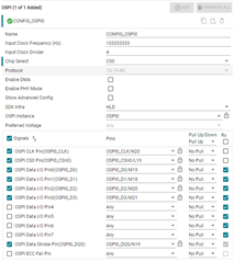
Checking Skip HW Init in the sysconfig settings resolved this non-terminating state.

However, it seemed that the flash open itself had failed, and the debug output from UART displayed "FLASH open failed for instance 0!!!".

After searching for where the failure was occurring, I found "status = SystemP_FAILURE" on line 901 of flash_nor_ospi.c.

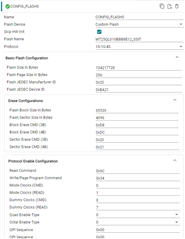
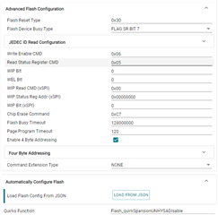
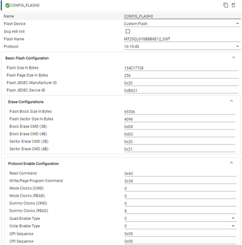
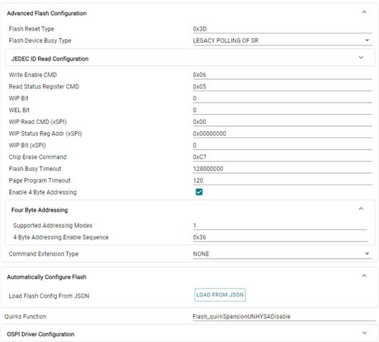
The failure occurred because the manufacturerId and deviceId read out were different from the values ​​set in sysconfig.

The ID values ​​read out were as follows: manufacturerId = 0xFF deviceId = oxFFFF

Notes

- Flash model number: MT25QL01GBBB8E12_0SIT (Micron)

- Uses an RTOS called "xxx".

- A development environment is used that matches the RTOS.

- Other functions such as GPIO and UART have been confirmed to work.

  • Hi,

    I see the flash you are using is: Flash model number: MT25QL01GBBB8E12_0SIT (Micron)

    I would like you to firstly run the OSPI Flash Diagnostics in order to get the Flash Configurations: software-dl.ti.com/.../CUSTOM_FLASH_SUPPORT_GUIDE.html

    Thanks,

    Vaibhav

  • Flash configuration has been obtained. The log is as follows.

    [OSPI Flash Diagnostic Test] Starting ...
    [OSPI Flash Diagnostic Test] Flash Manufacturer ID : 0x20
    [OSPI Flash Diagnostic Test] Flash Device ID       : 0xBA21
    [OSPI Flash Diagnostic Test] Executing Flash Erase on first block...
    [OSPI Flash Diagnostic Test] Done !!!
    [OSPI Flash Diagnostic Test] Performing Write-Read Test...
    [OSPI Flash Diagnostic Test] Write-Read Test Passed!
    [QSPI Flash Diagnostic Test] SFDP Information :
    ================================================
                          SFDP
    ================================================
    SFDP Major Revision                       : 0x1
    SFDP Minor Revision                       : 0x6
    Number of Parameter Headers in this Table : 2
    
    Types of Additional Parameter Tables in this flash
    ---------------------------------------------------
    4 BYTE ADDRESSING MODE INSTRUCTIONS TABLE
    JSON Data for the flash :
    
    {
    
            "flashSize": 134217728,
            "flashPageSize": 256,
            "flashManfId": "0x20",
            "flashDeviceId": "0xBA21",
            "flashBlockSize": 65536,
            "flashSectorSize": 4096,
            "cmdBlockErase3B": "0xD8",
            "cmdBlockErase4B": "0xDC",
            "cmdSectorErase3B": "0x20",
            "cmdSectorErase4B": "0x21",
            "protos": {
                    "p111": {
                            "isDtr": false,
                            "cmdRd": "0x03",
                            "cmdWr": "0x02",
                            "modeClksCmd": 0,
                            "modeClksRd": 0,
                            "dummyClksCmd": 0,
                            "dummyClksRd": 0,
                            "enableType": "0",
                            "enableSeq": "0x00",
                            "dummyCfg": null,
                            "protoCfg": null,
                            "strDtrCfg": null
                    },
                    "p112": {
                            "isDtr": false,
                            "cmdRd": "0x3C",
                            "cmdWr": "0x02",
                            "modeClksCmd": 0,
                            "modeClksRd": 1,
                            "dummyClksCmd": 0,
                            "dummyClksRd": 7,
                            "enableType": "0",
                            "enableSeq": "0x00",
                            "dummyCfg": null,
                            "protoCfg": null,
                            "strDtrCfg": null
                    },
                    "p114": {
                            "isDtr": false,
                            "cmdRd": "0x6C",
                            "cmdWr": "0x34",
                            "modeClksCmd": 0,
                            "modeClksRd": 1,
                            "dummyClksCmd": 0,
                            "dummyClksRd": 7,
                            "enableType": "0",
                            "enableSeq": "0x00",
                            "dummyCfg": null,
                            "protoCfg": null,
                            "strDtrCfg": null
                    },
                    "p118": {
                            "isDtr": false,
                            "cmdRd": "0x7C",
                            "cmdWr": "0x84",
                            "modeClksCmd": 0,
                            "modeClksRd": 0,
                            "dummyClksCmd": 0,
                            "dummyClksRd": 0,
                            "enableType": "255",
                            "enableSeq": "0x00",
                            "dummyCfg": null,
                            "protoCfg": null,
                            "strDtrCfg": null
                    },
                    "p444s": {
                            "isDtr": false,
                            "cmdRd": "0xEB",
                            "cmdWr": "0x02",
                            "modeClksCmd": 0,
                            "modeClksRd": 1,
                            "dummyClksCmd": 0,
                            "dummyClksRd": 9,
                            "enableType": "0",
                            "enableSeq": "0x14",
                            "dummyCfg": {
                                    "isAddrReg": false,
                                    "cmdRegRd":"0x00",
                                    "cmdRegWr":"0x00",
                                    "cfgReg":"0x00000000",
                                    "shift":0,
                                    "mask":"0x00",
                                    "bitP":0
                            },
                            "protoCfg": {
                                    "isAddrReg": false,
                                    "cmdRegRd": "0x00",
                                    "cmdRegWr": "0x00",
                                    "cfgReg": "0x00000000",
                                    "shift": 0,
                                    "mask": "0x00",
                                    "bitP": 0
                            },
                            "strDtrCfg": {
                                    "isAddrReg": false,
                                    "cmdRegRd": "0x00",
                                    "cmdRegWr": "0x00",
                                    "cfgReg": "0x00000000",
                                    "shift": 0,
                                    "mask": "0x00",
                                    "bitP": 0
                            }
                    },
                    "p444d": {
                            "isDtr": false,
                            "cmdRd": "0xEB",
                            "cmdWr": "0x02",
                            "modeClksCmd": 0,
                            "modeClksRd": 1,
                            "dummyClksCmd": 0,
                            "dummyClksRd": 9,
                            "enableType": "0",
                            "enableSeq": "0x14",
                            "dummyCfg": {
                                    "isAddrReg": false,
                                    "cmdRegRd":"0x00",
                                    "cmdRegWr":"0x00",
                                    "cfgReg":"0x00000000",
                                    "shift":0,
                                    "mask":"0x00",
                                    "bitP":0
                            },
                            "protoCfg": {
                                    "isAddrReg": false,
                                    "cmdRegRd": "0x00",
                                    "cmdRegWr": "0x00",
                                    "cfgReg": "0x00000000",
                                    "shift": 0,
                                    "mask": "0x00",
                                    "bitP": 0
                            },
                            "strDtrCfg": {
                                    "isAddrReg": false,
                                    "cmdRegRd": "0x00",
                                    "cmdRegWr": "0x00",
                                    "cfgReg": "0x00000000",
                                    "shift": 0,
                                    "mask": "0x00",
                                    "bitP": 0
                            }
                    },
                    "p888s": null,
                    "p888d": null,
                    "pCustom": {
                            "fxn": null
                    }
            },
            "addrByteSupport": "1",
            "fourByteAddrEnSeq": "0x36",
            "cmdExtType": "NONE",
            "resetType": "0x3D",
            "deviceBusyType": "0",
            "cmdWren": "0x06",
            "cmdRdsr": "0x05",
            "srWip":  0,
            "srWel":  0,
            "cmdChipErase": "0xC7",
            "rdIdSettings": {
                    "cmd": "0x9F",
                    "numBytes": 5,
                    "dummy4": 0,
                    "dummy8": 0
            },
            "xspiWipRdCmd": "0x00",
            "xspiWipReg": "0x00000000",
            "xspiWipBit": 0,
            "flashDeviceBusyTimeout": 128000000,
            "flashPageProgTimeout": 120
    }
    
    All tests have passed!!


  • Hi,

    The ID values ​​read out were as follows: manufacturerId = 0xFF deviceId = oxFFFF

    The reason for the manufacture and device id to be printed incorrectly is incorrect flash configurations in SysConfig.

    I want you to go ahead and check your application's sysconfig file namely example.syscfg

    Once there, you can open the GUI and then see there will be OSPI and FLASH section.

    We want to head to FLASH section and then simply fill up the obtained values.

    Please refer this: https://software-dl.ti.com/mcu-plus-sdk/esd/AM64X/11_00_00_15/exports/docs/api_guide_am64x/CUSTOM_FLASH_SUPPORT_GUIDE.html#autotoc_md681

    Thanks,

    Vaibhav

  • Following the method in the reference URL, I saved the information from "JSON Data for the flash" onwards to a JSON file and loaded it into sysconfig with the "LOAD FROM JSON" button.

    The contents of ti_board_open_close.c changed, so I replaced the source and ran it again, but there was no change in the result.

    The manufacturerId and deviceId became invalid values ​​and flash opening failed.

    What should I check?

  • Hi,

    Once you have the values modified, please go ahead and run the OSPI Flash IO application.

    If this results in manufacture and device id read failure, then please go ahead and send me a screenshot of the FLASH settings in SysConfig and OSPI settings as well.

    Regards,

    Vaibhav

  • This is a screenshot of the sysconfig when the ID reading failed.

    ospi settings

    flash settings

  • Hi,

    Thanks, I am comparing the values now with the datasheet. I will update you on further findings.

    Best,

    Vaibhav

  • Here are my thoughts:

    1. I see there is no DQS line for the flash you are using. Hence, this pin N19 can be unchecked from SysConfig in the OSPI section. I am referring the following datasheet: https://mm.digikey.com/Volume0/opasdata/d220001/medias/docus/2293/MT25QU01GBBB_DS.pdf, let me know if not this one, which one should I use for reference?
    2. Remove the quirks function option in the FLASH section.
    3. In FLASH section,
      1. set read command from 0x6C to 0x6B
      2. set write/page program command from 0x34 to 0x32
      3. Uncheck the enable 4 byte addressing option

    The goal here is to firstly make the flash operate in 3 byte addressing mode and then we can look for the 4 byte addressing mode later on.

    If you still run into problems while reading the manufacture and device id, then I can suggest next set of debug steps.

    Thanks,

    Vaibhav

  • Does 2. mean "leave the Quirks Function options field blank"? If the Quirks Function options field is left blank, an error occurs and the build will not proceed.

    I performed 1. and 3. and built, but there was no change in the status. The two IDs were not read correctly and Flash open failed.

  • Does 2. mean "leave the Quirks Function options field blank"? If the Quirks Function options field is left blank, an error occurs and the build will not proceed.

    Set this as NULL

    I performed 1. and 3. and built, but there was no change in the status. The two IDs were not read correctly and Flash open failed.

    Please read the following guide: Although for AM243, but can be followed for AM64x as well.

    A good start to this has been getting the OSPI Flash Diagnostics of the Flash. 

    Now, we need to start validation in the following way:

    1. Run OSPI Flash IO application:
      1. in 1s-1s-1s mode first to make sure connections to the flash are valid and the flash is actually running.
      2. once validated in 1s-1s-1s mode, we need to rerun the application in a protocol of your choice(which the flash supports).
    2. If the customer runs into problem running the OSPI FLASH IO in 1s-1s-1s mode, then the exact point of failure can be reported here on the e2e to which I can then provide further details on.
    3. How to run the first step: OSPI Flash IO Application?
      1. Download tera term software.
      2. Open the tera term software and open the COM PORT X of UART for AM243.
      3. Set the board in UART Boot mode.
      4. Send the SBL NULL Release HS FS file in the following manner [In order to know if HS FS or GP Images needs to be flashed, please check the device type by reading through this: https://e2e.ti.com/support/processors-group/processors/f/processors-forum/1228618/faq-am6xx-how-to-check-if-device-type-is-hs-se-hs-fs-or-gp ]


        NOTE: You need to send once and then after this send again as this overcomes a errata of warm reset. So basically, send the same SBL NULL Release HS FS file twice one after another.

      5. Once, done the cores will be initialized, post which you can then, open CCS and create the AM243.ccxml file from Target Configuration.
      6. Connect to the core in CCS and load the modified OSPI FLASH IO based on the OSPI Flash Diagnostics log you have found out. Try the step 1 from here onwards.

    Let me know if any more clarification is needed.

    NOTE: Please make sure if you run into error, please debug line by line and let me know the exact point so that I can help better on the resolution.

    Thanks,

    Vaibhav

  • The build passed when "NULL" was entered into the Quirks Function option.

    No change in status occurs even when all three conditions are met.

    The same occurs when the protocol is changed to "1s-1s-1s" and the settings are reflected using the "LOAD FROM JSON" button.

    However, the "TOPPER RTOS + RTOS Debugger" environment was used at this time. It has not yet been run in the "CCS + XDS200" environment.

    When reviewing the execution environment, several items were found that may be related to this problem.

    Please let us know if there are any incorrect usages among these.

    - Boot mode is set to OSPI boot mode.

    - Attempting to open Flash with SBL written in it with an application.

    - SBL based on the sample code "sbl_null" is used, but OSPI and Flash settings have not been added to sysconfig

  • The build passed when "NULL" was entered into the Quirks Function option.

    Thanks on the confirmation.

    Boot mode is set to OSPI boot mode

    If bootmode is set to OSPI bootmode, that would not work as you have a QSPI flash.

    I would like you to read the following response: 

    "

    A good way to approach this to is to read the way booting happens in a specific bootmode.

    For example:

    SPI bootmode: 1s-1s-1s operation and 0x3 command is issued followed by 24 bit address and 0 dummy cycles.

    xSPI bootmode: 1s-1s-1s operation and 0xB(fast read) command is issues followed by 24 bit address and 8 dummy cycles.

    Now coming back to the flash datasheet:

    For SPI Bootmode, the description from TRM matches whats mentioned in the datasheet of the flash:

    For xSPI bootmode, the description matches the TRM as well:

    So yes booting in SPI and xSPI(1s-1s-1s Fast Read) is okay.

    Let put some lime light on the QSPI bootmode and how it operates.

    You see that in the above flash datasheet description it is mentioned that 0x6B is issued + 24 bit address + 8 dummy clocks

    The same is mentioned in the TRM of AM64x as well:  0x6B is issued + 24 bit address + 8 dummy clocks

    But from the flash datasheet one thing is very important:

    "The quad mode command 35h needs to be issued to enter the Quad Input/output mode and hence boot from QSPI bootmode"

    Currently ROM does not support sending the quad mode enable command on its own.

    "

    Thanks,

    Vaibhav

  • I checked the boot mode that I had been using until now.

    As you pointed out, the OSPI boot mode was incorrect.I am using QSPI boot mode.

    I also confirmed that it works when I change to OSPI boot mode and start it up.

    When operating in this state, I cannot confirm the SBL_NULL debug output from UART.

  • Hi,

    As you pointed out, the OSPI boot mode was incorrect.I am using QSPI boot mode.

    Thanks for acknowledging.

    I also confirmed that it works when I change to OSPI boot mode and start it up.

    Please reconfirm if you meant to write QSPI bootmode here instead of OSPI bootmode?

    When operating in this state, I cannot confirm the SBL_NULL debug output from UART.

    Please clarify further more on this one.

    Thanks,

    Vaibhav

  • I don't know how to quote a comment so I use the > symbol.

    >Please reconfirm if you meant to write QSPI bootmode here instead of OSPI bootmode?

    I confirmed that it did not work properly when set to OSPI boot mode. "OPSI" is not a typo.

    >Please clarify further more on this one.

    I tried to confirm that I had mixed up the boot mode settings, OSPI and QSPI.

    I made it possible to check the output from the UART with tera term and supplied power to the AM6442.

    When I performed this operation in QSPI boot mode, I was able to see a display in tera term beginning with "Starting NULL Bootloader ...".

    When I performed this operation in OSPI boot mode, nothing was displayed on tera term.

  • Hi Takeshi,

    When I performed this operation in QSPI boot mode, I was able to see a display in tera term beginning with "Starting NULL Bootloader ...".

    When I performed this operation in OSPI boot mode, nothing was displayed on tera term.

    So booting in OSPI bootmode will not be supported for the flash you are using, because the flash itself does not support it.

    Thanks,

    Vaibhav

  • Since flash opening fails in the "TOPPER OS IDE + dedicated debugger" environment, the following test code was run in the "CCS+XDS200" environment.

    #include <kernel/dpl/DebugP.h>
    #include "ti_drivers_open_close.h"
    #include "ti_board_open_close.h"
    #include <string.h>
    
    #define APP_OSPI_FLASH_OFFSET_BASE  (0x200000U)
    
    #define APP_OSPI_DATA_SIZE (2048)
    uint8_t gOspiTxBuf[APP_OSPI_DATA_SIZE];
    /* read buffer MUST be cache line aligned when using DMA, we aligned to 128B though 32B is enough */
    uint8_t gOspiRxBuf[APP_OSPI_DATA_SIZE] __attribute__((aligned(128U)));
    
    void ospi_flash_io_fill_buffers(void);
    int32_t ospi_flash_io_compare_buffers(void);
    
    void ospi_flash_io_main(void *args)
    {
        int32_t status = SystemP_SUCCESS;
        uint32_t offset;
        uint32_t blk, page;
        Flash_Attrs *flashAttrs;
        char stepflag[80];
    
        /* Open OSPI Driver, among others */
        Drivers_open();
        /* Open Flash drivers with OSPI instance as input */
        status = Board_driversOpen();
        DebugP_assert(status==SystemP_SUCCESS);
    
        flashAttrs = Flash_getAttrs(CONFIG_FLASH0);
    
        DebugP_log("Execute step by step?(y = step by step):");
        DebugP_scanf("%s", &stepflag);
    
        /* Fill buffers with known data,
         * find block number from offset,
         * erase block, write the data, read back from a specific offset
         * and finally compare the results.
         */
    
        offset = APP_OSPI_FLASH_OFFSET_BASE;
        ospi_flash_io_fill_buffers();
        status = OSPI_enableDacMode(gOspiHandle[CONFIG_FLASH0]);
        if(strcmp(stepflag, "y") == 0)
        {
            do
            {
                stepflag[0] = '\0';
                DebugP_log("Continue?(y = Continue):");
                DebugP_scanf("%s", &stepflag);
            }while(strcmp(stepflag, "y") != 0);
        }
    
        Flash_offsetToBlkPage(gFlashHandle[CONFIG_FLASH0], offset, &blk, &page);
        status = Flash_eraseBlk(gFlashHandle[CONFIG_FLASH0], blk);
    
        if(status == SystemP_SUCCESS)
        {
            DebugP_log("Block Erase of %d bytes Success at 0x%X offset !!!\r\n", APP_OSPI_DATA_SIZE, offset);
        }
        else
        {
            DebugP_log("Block Erase of %d bytes Fail at 0x%X offset !!!\r\n", APP_OSPI_DATA_SIZE, offset);
        }
        if(SystemP_SUCCESS == status)
        {
            if(strcmp(stepflag, "y") == 0)
            {
                do
                {
                    stepflag[0] = '\0';
                    DebugP_log("Continue?(y = Continue):");
                    DebugP_scanf("%s", &stepflag);
                }while(strcmp(stepflag, "y") != 0);
            }
    
            status = Flash_write(gFlashHandle[CONFIG_FLASH0], offset, gOspiTxBuf, APP_OSPI_DATA_SIZE);
            if(status == SystemP_SUCCESS)
            {
                DebugP_log("Flash Write of %d bytes Success at 0x%X offset !!!\r\n", APP_OSPI_DATA_SIZE, offset);
            }
            else
            {
                DebugP_log("Flash Write of %d bytes Fail at 0x%X offset !!!\r\n", APP_OSPI_DATA_SIZE, offset);
            }
        }
        if(SystemP_SUCCESS == status)
        {
            if(strcmp(stepflag, "y") == 0)
            {
                do
                {
                    stepflag[0] = '\0';
                    DebugP_log("Continue?(y = Continue):");
                    DebugP_scanf("%s", &stepflag);
                }while(strcmp(stepflag, "y") != 0);
            }
    
            status = OSPI_enableDacMode(gOspiHandle[CONFIG_FLASH0]);
            status = Flash_read(gFlashHandle[CONFIG_FLASH0], offset, gOspiRxBuf, APP_OSPI_DATA_SIZE);
            if(status == SystemP_SUCCESS)
            {
                DebugP_log("Flash Read of %d bytes Success at 0x%X offset !!!\r\n", APP_OSPI_DATA_SIZE, offset);
            }
            else
            {
                DebugP_log("Flash Read of %d bytes Fail at 0x%X offset !!!\r\n", APP_OSPI_DATA_SIZE, offset);
            }
        }
        if(SystemP_SUCCESS == status)
        {
            status |= ospi_flash_io_compare_buffers();
        }
    
        offset = APP_OSPI_FLASH_OFFSET_BASE + (flashAttrs->blockSize*2);
        ospi_flash_io_fill_buffers();
    
        if(strcmp(stepflag, "y") == 0)
        {
            do
            {
                stepflag[0] = '\0';
                DebugP_log("Continue?(y = Continue):");
                DebugP_scanf("%s", &stepflag);
            }while(strcmp(stepflag, "y") != 0);
        }
    
        Flash_offsetToBlkPage(gFlashHandle[CONFIG_FLASH0], offset, &blk, &page);
        status = Flash_eraseBlk(gFlashHandle[CONFIG_FLASH0], blk);
    
        if(status == SystemP_SUCCESS)
        {
            DebugP_log("Block Erase of %d bytes Success at 0x%X offset !!!\r\n", APP_OSPI_DATA_SIZE, offset);
        }
        else
        {
            DebugP_log("Block Erase of %d bytes Fail at 0x%X offset !!!\r\n", APP_OSPI_DATA_SIZE, offset);
        }
        if(SystemP_SUCCESS == status)
        {
            if(strcmp(stepflag, "y") == 0)
            {
                do
                {
                    stepflag[0] = '\0';
                    DebugP_log("Continue?(y = Continue):");
                    DebugP_scanf("%s", &stepflag);
                }while(strcmp(stepflag, "y") != 0);
            }
    
            status = Flash_write(gFlashHandle[CONFIG_FLASH0], offset, gOspiTxBuf, APP_OSPI_DATA_SIZE);
            if(status == SystemP_SUCCESS)
            {
                DebugP_log("Flash Write of %d bytes Success at 0x%X offset !!!\r\n", APP_OSPI_DATA_SIZE, offset);
            }
            else
            {
                DebugP_log("Flash Write of %d bytes Fail at 0x%X offset !!!\r\n", APP_OSPI_DATA_SIZE, offset);
            }
        }
        if(SystemP_SUCCESS == status)
        {
            if(strcmp(stepflag, "y") == 0)
            {
                do
                {
                    stepflag[0] = '\0';
                    DebugP_log("Continue?(y = Continue):");
                    DebugP_scanf("%s", &stepflag);
                }while(strcmp(stepflag, "y") != 0);
            }
    
            status = Flash_read(gFlashHandle[CONFIG_FLASH0], offset, gOspiRxBuf, APP_OSPI_DATA_SIZE);
            if(status == SystemP_SUCCESS)
            {
                DebugP_log("Flash Read of %d bytes Success at 0x%X offset !!!\r\n", APP_OSPI_DATA_SIZE, offset);
            }
            else
            {
                DebugP_log("Flash Read of %d bytes Fail at 0x%X offset !!!\r\n", APP_OSPI_DATA_SIZE, offset);
            }
        }
        if(SystemP_SUCCESS == status)
        {
            status |= ospi_flash_io_compare_buffers();
        }
    
        if(SystemP_SUCCESS == status)
        {
            DebugP_log("All tests have passed!!\r\n");
        }
        else
        {
            DebugP_log("Some tests have failed!!\r\n");
        }
    
        Board_driversClose();
        Drivers_close();
    }
    
    void ospi_flash_io_fill_buffers(void)
    {
        uint32_t i;
    
        for(i = 0U; i < APP_OSPI_DATA_SIZE; i++)
        {
            gOspiTxBuf[i] = i % 256;
            gOspiRxBuf[i] = 0U;
        }
    }
    
    int32_t ospi_flash_io_compare_buffers(void)
    {
        int32_t status = SystemP_SUCCESS;
        uint32_t i;
    
        for(i = 0U; i < APP_OSPI_DATA_SIZE; i++)
        {
            if(gOspiTxBuf[i] != gOspiRxBuf[i])
            {
                status = SystemP_FAILURE;
                DebugP_logError("OSPI read data mismatch !!!\r\n");
                break;
            }
        }
        if(SystemP_SUCCESS == status)
        {
            DebugP_log("OSPI read data match !!!\r\n");
        }
        return status;
    }
    

    The OSPI and FLASH settings in sysconfig are as shown in the screenshot below.

    The debug output resulting from execution is as shown in the image.
    Flash opening itself is successful if the execution environment is changed.

  • Thanks for the update.

    So changing the environment to ccs + xds 200 debugger, makes the application run, whereas for topper os ide + another debugger, the same application was failing. 
    Let me know if my understanding is correct, then I can proceed to highlight if there is any environment dependency.

    Looking forward to your response.

    Thanks,

    Vaibhav

  • >So changing the environment to ccs + xds 200 debugger, makes the application run, whereas for topper os ide + another debugger, the same application was failing. 

    That's correct.
    This is how I debug and run the test code.

    https://software-dl.ti.com/mcu-plus-sdk/esd/AM64X/11_00_00_15/exports/docs/api_guide_am64x/CCS_LAUNCH_PAGE.html

  • Hi Takeshi,

    Thanks for the confirmation.

    ccs + xds 200 debugger

    Are you planning to stick to this environment for further development or you would like to stick to "topper os ide + another debugger"

    Please let me know.

    Thanks,

    Vaibhav

  • We plan to use "topper os ide + another debugger" for future development.

  • We discovered the reason why Flash could not be opened normally.

    The default value of the GPIO related to Flash was set to reset Flash, causing it to become unresponsive.

    By changing the default GPIO value from sysconfig, we were able to check the operation of Flash.