This thread has been locked.

If you have a related question, please click the "Ask a related question" button in the top right corner. The newly created question will be automatically linked to this question.

TMS320C6713B fails to run

Other Parts Discussed in Thread: TMS320C6713B

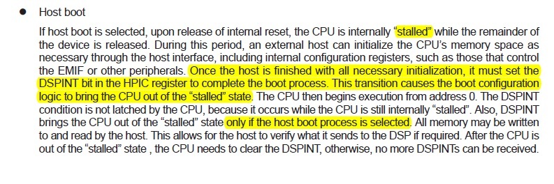
We are having an in issue with a TMS320C6713B.  Most of the time, our code is executing with no issues; we power up using Host Boot mode and all is well.  However, sometimes on power up we program in Host Boot mode (and read back the checksum over the HPI bus and all appears to be well), but the processor appears to never start.

We have checked the state of all HD pins when the reset is released.  They all appear OK, including the 'Do Not Oppose' pins in the datasheet.

We have checked the nTRST, EMU0/1 and they are the correct state on power up.  The CLK0 pin is also correct.

We have checked the length of the rest pulse.  It  quite sufficient and appears stable (no extra glitches).  We have verified that the reset pulse occurs after the power supplies are stable.

We have altered the power supply sequencing so that the 3.3V doesn't even start coming up until the core voltage is stable.  No change.

What are some other things we should be checking?  It is very odd in that once the processor does not start on a power up, subsequent pulses of the reset line do nothing....  it is some state on a particular power up that is permanent until we cycle the power again.

Thanks in advance for any support!

  • hallo Katherine,

    this seems to be very similar to my problem.

    http://e2e.ti.com/support/dsp/tms320c6000_high_performance_dsps/f/115/t/151810.aspx#549327

    I still have no answer from anybody!

    We also checked the power up, the signals of HPI, JTAG, all seems to be ok!

    I will give you all information when I've got an answer!

    best regards

    Ralf


  • Katherine,

    Welcome to the TI E2E forum. I hope you will find many good answers here and in the TI.com documents and in the TI Wiki Pages. Be sure to search those for helpful information and to browse for interesting topics.

    Debugging board-level or non-digital logic device problems are among the most difficult tasks you will have to do. It would be nice if we could tell you immediately to do something like re-solder the TRSTn pin or replace the external resistor on the RESETn signal, but there are easily twice as many possible causes of these problems as there are pins and components on the board.

    We have written some application notes and Wiki topics to give you some guidance in this tough process. In the TI Wiki Pages, search for "hardware debug" (no quotes) and also for "checklist" (no quotes) to find some pages with helpful information. You might try searching on C6713 terms also.

    Because it was not listed on the TMS320C6713B Product Folder under Technical Documents (it should be, in my opinion), I had a hard time finding the TMS320C6713 Hardware Designer's Resource Guide so I have provided a direct link to it here. In other cases I would make you search for the document when it is in one of the usual places, so you can become familiar with the documentation sources we have. For this one, I had to click under the list of Application Notes on View Application Notes for TMS320C67x DSP, then type hardware in the Document Title box on the search screen. Clicking Search returns 3 docs and one was this one. That is a lot to go through, but now you have another way to find documents plus you have the link to this helpful one.

    The datasheet has specifics on things like power sequencing and voltage levels and clock & reset requirements. All of these must be met as specified there. It is a tedious task to go through checking every pin, but that is sometimes what you have to do. You have already gone through the first phase of debugging and ruled out a lot of things.

    There have been cases where someone reported that all the power pins were at the right value, but later reported that one pin was not connected or had a bad solder joint or the voltage was actually too low when compared to the datasheet.

    None of this directly helps you, but I think there is a lot of information for additional guidance in these resources.

    My guess is that this is related to power supplies or poorly initialized signal pins (weak pull-up or pull-down). But there could be too many other things to guess.

    If the DSP has a CLKOUT pin, that is always good to confirm that the device has some life. Watching some outputs before and after reset is released could also confirm that some part of the device is operating well, or when it fails you can see that these do not operate the same.

    Please keep us posted on your progress.

    Regards,
    RandyP

  • Hello Randy,

    I still have not found a solution to the issue.  I have yet to find a specification violation (not saying there couldn't be one... but I haven't found it yet).  It appears that the core is just not starting on certain power ups.

    Yesterday, we measured the EMIF Clk pin that goes to the RAM we are running out of.  There is a clock there after the DSP turns on, and the clock runs while we program the RAM through the DSP via our HPI interface with the host.  We do successfully read back the image from the RAM.    When things run successfully, the clock frequency of this pin changes dramatically after the DSPINT bit is written (and the DSPINT bit is written - we have read that register back over the HPI bus on a success and failure in booting).

    When we have a boot failure, that frequency does NOT change after writing the DSPINT bit - which also would seem to point at the dsp core not starting up when the DSPINT bit is written.

    What can so severely lock up a DSP that not only does it fail to boot properly, but subsequent pulses of the reset line do nothing at all?  It is in such a latched up state that it requires a full power cycle to come back up.

    This issue seems to be more severe at cold temperatures, btw...  Not sure what this might mean, but I thought I'd mention it.

    Is there some sort of a test mode we could be booting up into?  Are there any registers that I can try to read over the HPI interface that might indicate this invalid mode?  If we were in a test mode, what could I do to get out of it?

    Thank you for any thoughts on the matter,

    Katherine

  • Katherine,

    If you would, please copy the post that you made on Ralf's thread to a new post on this thread so that information will be available to people looking at this thread.

    I have some questions that may help shed more light on the situation. If you have some answers now, please go ahead and post those rather than wait for any that might be more time consuming.

    1. How many boards do you have and how many show this problem?
    2. A really valuable data point is usually to swap parts between a working board and a failing board, but this is not trivial. Can you do this or have you done this? It pretty quickly tells you if the problem is with the board components (failures follow the board) or the board manufacturing (both boards start to pass or both fail) or the DSP (failures follow the DSP). Of course, manufacturing problems can falsely cause the problem to appear to be board components or the DSP, but that is a lower probability.
    3. What are the approximate probabilities of failure on the failing boards at room temp and cold temp? How cold?
    4. If you power down after a failure and immediately power back up, will it always pass?
    5. If you power down after a failure and wait a while before powering back up, will the failure return to the probability in #2? How long?
    6. What are the frequencies of the EMIF Clk pin before and after writing to DSPINT on a passing board?
    7. What is the datasheet name of the EMIF Clk pin you are monitoring?
    8. What is on the EMIF ClkIn pin before and after DSPINT?
    9. What are the states of ARDY, HOLDz, HOLDAz, and the four CSnz pins after DSPINT when it fails?
    10. Can you get the code developer back to help run the emulator for some internal inspection or for creating test images?
    11. Which emulator and version of CCS do you use?
    12. Do you always read back the image via HPI before hitting DSPINT, and it always reads back okay even when a failure then occurs?
    13. When it fails to run, can you still read back the loaded image and it still matches?
    14. What devices do you have on the EMIF bus and which CSn are they on?
    15. What frequencies are on CLKIN, CLKOUT2, CLKOUT3, and CLKMODE0 before and after DSPINT on a failure?
    16. What is on NMI after DSPINT on a failure?
    17. When does NMI go high during the power sequencing and reset? Does it ever pulse low after reset has been released?

    Those are all I can think of right now. Some of the answers may lead to more.

    But you deserve some answers after getting all of these questions.

    "What can so severely lock up a DSP ..."  Usually this is going to be related to power sequencing or reset timing. Reset should be protected from timing constraints relative to CLKIN or CLKOUT2, but that could be something to look at, too.

    "more severe at cold temperatures, ..."  This could be an aid in debug, except that you might have to put one of your tech's and a scope in the temperature chamber or outdoors. (Sorry, it's late and I'm getting tired. It really could be an aid, though, if it means the probability goes up.)

    "Is there some sort of a test mode we could be booting up into?"   On some of our parts, some of the reserved pins are used for setting manufacturing test modes. If you have some bad connections on some of those pins or not connected right, that would be the only way to get into one of those modes. The other way could be if the JTAG pins were at bad states, especially EMU0/1 not being pulled high but that would also require some noise on TRST and/or TCK.

    Regards,
    RandyP

  • Hi Randy,

    I'll answer what I can right now and try to get the rest soon.

    (1)  At least 10% of the boards are showing this issue, and it might be higher.  We have definitely reproduced the issue on at least 10% at this point.

    (2) Replacing a 272 pin Lead Free BGA package on a double sided board is definitely non-trivial.  At this point, we have not been able to do this.

    (3) We have been using a temperature chamber.  If we let a "bad" board sit for approximately 5-10 minutes at 0C when it is turned off, it generally won't boot up properly.  If we immediately cycle power after a board has been on, even at 0C, it generally restarts.   What we seem to be seeing is that if a board fails at room temp, it fails even more often at 0C.  If a board does not fail at 0C, we generally cannot get it to fail at room temp.  However, the testing is not absolute, but the probabilities of failure are there.  We have some boards that will fail almost every time on the first boot at 0C.  We have other boards that we cannot get to fail.

    (4) See (3) - No, it will not always pass, but the probability is higher that it will.

    (5) This seems to vary... some boards it seems to be minutes... other boards well over half an hour. 

    (6) I believe it was around 18.7 Mhz before.... I think it was about 80 Mhz (I remember it was several times higher) after but I don't have a scope right in front of me to take the measurement at the moment and I didn't write the number down.  I can recheck this tomorrow. 

    (7)ECLKOUT

    8,9  Uncertain - haven't measured them

    (10) No, I'm on my own there

    (11) I am not certain - I have not used Code Composer on this project.  I just have the output file.

    (12)  Yes, we always read and it is always OK

    (13) Yes, we always read and it is always OK

    (14) We have an ISSI SDRAM on CS0 and CS2/3 are connected to an FPGA

    (15-17)  I haven't done a specific check of those before and after we write to  DSPINT on a failure.  I will have to remeasure.

    Can you be more specific on how to 'protect reset from timing constraints'?

    We do have EMU0/1 pulled high, and NTRST low.  The other JTAG pins are floating.

    Thanks,

    Katherine

  • Hi Katherine

    How are you initialising the PLL? If you're booting from the HPI, the PLL comes up at 50MHz and you have to set up the registers first thing in your code. If you don't follow the TI guidelines on order of operations and delays, it may not start reliably.

    Also, the HPI timings are slower before the PLL has been initialised, because the clock to the DSP's HPI hardware is slower. This has caused me mysterious crashes in the past.

    If you want to get the max speed out of the HPI, you have to slow down your host processor's bus timings while you load the code into the DSP, and then speed them up once you know the DSP has initialised and got up to full clock speed.

    Steve Conner

  • Hi Steve,

    Thanks for the comments.  The PLL is initialized in the code - I did not write that code, but I can tell it is done very early on (I believe it is one of the first things done).   With that , we see failures.  We have also tried initializing the PLL prior to programming over HPI (although the datasheet does strongly recommend against setting up the PLL via HPI....).  We still have the lock up failures - it made no difference. 

    I have also looked at the address lines on the EMIF on a failure - we don't seem to see any movement when they fail.  It doesn't seem like a bad access - it seems like no access is even attempted.  Could that be caused by a PLL mis-start?  Seems that we should see some accesses as the PC starts at 0, and it doesn't look like we are.

    When you mention you had mysterious crashes - was the DSP totally locked up and would not recover until power (both core and IO) were cycled?  IE - even trying to re-do the boot sequence  starting with re-asserting the /reset pin did not work?

    Thanks!

    -Katherine

  • Hi Katherine

    In our system, the failure mode is that the HPI locks up and brings the host processor down with it, so there's no way of trying to redo the boot sequence other than cycling the power to the whole instrument.

    The fault has a similar profile in that about 10% of units in the first production batch did it, but neither of the development prototypes did, so we couldn't see it coming until it was too late. We also got a bunch of genuinely bad boards where the DSP wasn't soldered properly, which confused the issue: two separate problems that could have the same symptoms.

    We don't have an environmental chamber, so I plan to abuse some of the marginal units with a heat gun after reading your posts.

    Talking of heat, if the PLL failed to initialise, the DSP chip will stay cool to the touch, since the power dissipation depends on clock rate. Our 300MHz parts get toasty pretty quick once they get going.

    I see you're running code out of external memory, which we're not. Is it possible that your external memory timings might be marginal for the memory chips you're using? You wouldn't notice when loading and verifying the image, because the DSP is still running slow. It doesn't boost to full speed until the PLL setting code in the image executes. (Your attempt to set the PLL over the HPI may just have done nothing.) Anyway, try heating up the memory chips on a known good board while it's running, and see if it falls over. You could also try the PLL over HPI again, and verify that the DSP gets hot, then you can see if the image has errors when read back at the fast timings.

    Final question: If you're loading code into the external memory over HPI, how do you set up the EMIF so as to be able to access external memory in the first place? Do you poke the registers over HPI? Does the code then reset them to something else when it runs? (DSP/BIOS has an EMIF configuration thing)

  • Hi Steve,

    Strange that your problem seems to mirror ours in a very unfortunate manner - we also saw no issues with the first couple of prototypes.  Our first production batches are what caught our attention, although it now seems that the pilot build may have had a single board with a failure but it was not caught until later.

    Yes, I know what you are talking about with respect to PLLs and heat.  If we turn on the PLL over the HPI we see a nice big increase in current as the PLL initializes.  If we initialize the PLL in code, we see this change as the code begins to execute.  I did not compare the EMIF clock speed to the RAM in the two different cases of when the PLL is initialized - although the part did pull more current, I'm not sure that changed the clock to the RAM during the load process.  I will look at this today. 

    I have started checking the memory timings - including changing wait states and such to see if that helped/hindered.  It really doesn't look like that is the issue at this point, but I am not sure it has been entirely ruled out.  I plan to look at this further today.  I will try and characterize better at the hot temps today and see how much the probability of failure improves.

    We program the EMIF over HPI.  I did remove that EMIF initialization and we don't read back the same values we send to the RAM in that case - so it is necessary for our RAM chip.  You have access to pretty much everything over HPI.

    You mention that your failure is that the HPI locks up....  can you be a little more specific?  And (sorry, this was unclear to me from your posts) is your issue fixed, or are you still trying to work through it?   Are you unable to read/write successfully over the HPI interface at that point?  If so, that is not the same issue we are seeing.  We seem to be able access the HPI just fine, although knowing what you see specifically might give me something else to look at to verify that is the case.  Our programming and readback are done before we are trying to execute code.  Only recently, during our debug, after we write the DSPINT bit, we did add a bit of code so can read it back and verify it.  The failure seems to be that the DSP doesn't even try to run.

  • Hi Katherine

    Well both our problems seem similar because it's the classic signature of a timing or race problem, even if it's a different parameter that we're violating. You figure out timings that work on the prototypes, but when you go into production you encounter a wider spread. Or a marginal pull-up resistor, or even the pull-up missing entirely. (what if the processor doesn't reliably go into HPI boot mode at power-up?)

    In a word, some sort of analog thing. If Bob Pease were alive he'd tick us both off for not reading the datasheets and doing good worst-case design, but Pease probably never had to deal with a part that had 10 data books of 500 pages each.

    It could also be bad BGA soldering, as that responds to temperature. The trick is to tell them apart: gently warping the board won't affect timing but can make a marginal BGA soldering job fail permanently.

    Some more things that come to mind: The DSP needs its bus left floating around reset time, for proper boot mode selection and to avoid entering the test modes mentioned earlier. So, you can't necessarily connect the HPI straight to a bus that's shared by other peripherals, in case the host decides to access one of them while the DSP is powering up.

    Our problem is still unresolved, and it might well not have a lot to do with yours, as we bought our DSPs in on modules and they boot from flash ROM. We had one more unit fall down in the field yesterday after a firmware upgrade.

    But all of these issues are in my mind because I'm working on my first board design with the C6713B (HPI boot now) and agonising over getting all those pullup resistors right. :-) I have a prototype that runs with one of the modules modified for HPI boot, and I discovered the timing issues while trying to get that working.

    Steve

  • Katherine,

    RandyP said:
    Reset should be protected from timing constraints relative to CLKIN or CLKOUT2

    This was very poorly worded. I meant that our design methods can be expected to have been done so that there is no timing constraint on NRESET w.r.t. CLKIN or CLKOUT2. If that became a question to be looked at, you could use a flip-flop outside the device to force NRESET to go high only at a certain edge of one of those, but that is a long-shot and would not be a logical cause of a high probability of failure unless you are generating NRESET synchronous to one of those clocks (I do not know which one NRESET is actually latched by inside the DSP).

    Discussion said:

    10.Can you get the code developer back to help run the emulator for some internal inspection or for creating test images?
    (10) No, I'm on my own there

    11.Which emulator and version of CCS do you use?
    (11) I am not certain - I have not used Code Composer on this project.  I just have the output file.

    One of the first things you would want to know in a case like this is whether the DSP is alive and running in bad space or whether the DSP is dead and not running at all. Someone experienced with CCS and emulation is needed to do that connection, find out if you can connect to a failed device and if so, where the PC is at that time.

    Another thing to try will be a small code image that just spins at or around 0 to see if the PC starts there and then gets lost or never runs valid code there. And building from one of Steve Conner's comments, putting all of a test image into internal memory to see if it will pass better would help.

    Katherine Foote said:
    We do have EMU0/1 pulled high, and NTRST low.  The other JTAG pins are floating.

    It would be a worthwhile test to put assisting 10K-Ohm pull-ups on the TMS, TCK, TDI, EMU0, and EMU1 lines. There could be some configuration pins that use the internal IPU/IPD that you should try weak assisting resistors on pins left floating.

    You have some good ideas from Steve to work with, too. One variant of the heat gun would be to use a targeted cold spray to see if a cold DSP or cold SDRAM or cold power supply parts increase the failure rate. In the cold chamber, can you hang a heat gun pointing at those to do the inverse test?

    Regards,
    RandyP

  • Katherine,

    A test I forgot to add would be to not use any PLLs and see if it behaves differently.

    First, try disabling the PLL using the bootstrapping pins. Second, change the code to not enable or change the PLL.

    If you disable the PLL, you may have to change the HPI cycle times drastically to match up with the slower clock. What frequency is CLKIN? You can look at CLKOUT2 to see what frequency the DSP is getting clocked at.

    The result of this will be a good clue no matter the outcome.

    Regards,
    RandyP

  • Katherine,

    Any updates? Is your problem solved? If so, please reply back with the solution.

    Regards,
    RandyP

  • Hi Randy,

    Some additional results:

    We now have an XDS510USB emulator and the most recent version of Code Composer Studio 5.  We are unable to connect with the emulator to a failed board, although we can successfully connect to a board running normally.  It would appear that the JTAG interface is totally dead.

    We tried adding the pullups to the JTAG lines (had them already on EMU0/1) and a pull down on NTRST.  No change.

    Some of the measurements you asked for:

    CLKout2 pin - on a successful boot, it has been reconfigured ast GP2 and has a signal with frequency around 562 Khz (not a constant clock, but the pulses are that frequency).

    CLKout2 pin - on a failed boot, it is 18.75 Mhz

    CLKout3 - on a successful boot, it is 37.8 Mhz.  On a failed boot, it is 4.68 Mhz

    CLKMODE 0 - always seems to be high, fail or success.

    NMI - always seems to be low, fail or success.

    ARDY, HOLDz, HOLDaz are not accessible (not connected to anything and can't get to the pin.  After a failure, CE0 is high with two 55ns low pulses occurring 213 ns apart approximately every 45us.  CE1 and 2 and 3 are high.

    I haven't been able to try anything with the PLL yet from your later post.

    Best regards,

    Katie

  • Katherine,

    This may seem basic but I ask this in regards to comments about effects of temperature.

    Are there any observable differences, or even marginal situations, when looking at the input clock stability relative to when the power supplies are ramped and stable as well as the reset input?  The input clock should be valid and stable prior to the release of reset.

  • Hallo Katherine,

    here are our newest state, after having got some hints from europeen customer venter in Munich.

    They pointed out to the ERRATA-Sheet and there to the PULL-UPs and -Downs at the JTAG signals

    and e.g. CLKOUT3 (we do not use this PIN). I asked them about second functions of this PIN during Reset

    or Start, but have no answer. Indeed the Errata says, that all this informations about the PU and PD Resistors

    are only important, when DEVCFG.0 is set to "1". Our DEVCFG shows alway a "0" for this Bit, as reported earlier.

    Nevertheless we tried this PU/PD's, witout any success as earlier attempts at other signals.

    Should we share our HPI and JTAG design. Do not hesitate to say yes, and I will post my e-mail adress in this blog!

    br Ralf

  • Hi Brandon,

    We had looked at the clock initially in our first round of debug (lockup generally is from bad clocks or bad power...), but we haven't seen any difference in the clock between a successful and failed boot.  I rechecked again to make sure, and I'm not seeing any difference.  Frequency looks the same, levels seem to be the same.

    Is there something very subtle I should be looking for?  Are you talking about a gross failure?  How long prior to the release of reset should the clock be stable?  us?  ms?

    Thanks!

    -Katie

  • My suggestion would be to write the smallest piece of code possible to test things out.  Specifically:

    • It should reside entirely in internal RAM.
    • It should NOT configure the PLL/EMIF.
    • The only thing you might do is to turn on an LED so you get a visual that it's alive.
    • It should then just spin in an empty while(1) loop.

    A piece of code written in this manner will make it easier to determine if there is any kind of software dependency, e.g. if the PLL setup code is doing something wrong or if perhaps an illegal address is being accessed, etc.

  • Sounds like blaming the programmer here!

    I got my problem fixed, and it was bad code. I had the main processor send a bad command to the DSP, and as far as I could tell, this caused it to set up the EDMA controller with random values from uninitialised memory.

    On some samples of the chip, that would have no obvious effect, but on others it would cause rogue DMA transfers to overwrite the internal memory including my code, the state of the HPI state machine and so on. At least, this is what I could figure out from piecing together the wreckage.

    So yeah, blame the programmer. We're quite capable of screwing things up completely without help from the hardware guys! :-)

    Katherine, can you read back the memory AFTER the processor has tried to boot and failed, to see if it has got corrupted when the processor starts?

    Steve

  • Hi Steve,

    Yes, this seems to be where our issue is a little different than yours.  I did do a test last week where I tried to read back the memory after the processor starts, and after it gets a failed start command.

    Here's what I've seen:

    When the processor is successfully running, and I tried to read back the RAM values, I get a checksum error.  I think this is due to either (1) some timing issue since I'm trying to read from what I'm running from or (2) a scratchpad value that was initialized to 0 when it was programmed, and has now changed because the processor is running.

    When the processor is in the 'failed' state, after writing the DSPINT bit (which should be starting the core), I can read back the code and the checksum matches what I send.  From what I have seen, the HPI bus is in perfect condition, but our core is just not running.  It is not running to the point that we cannot connect the JTAG emulator.

    If I read back the ram prior to the DSPINT bit, whether the processor is going to run or not, I always read the correctly programmed checksum.

    I'm very glad to hear that you've solved your issue!!!  Even though it would appear that our issues are not the same, it does give hope!

    To clarify what you've said - you were sending the 'bad' command over HPI, right?  It wasn't an 'bad' code segment that the DSP was executing?

    Best regards,

    Katherine

  • Katherine Foote said:
    When the processor is successfully running, and I tried to read back the RAM values, I get a checksum error.  I think this is due to either (1) some timing issue since I'm trying to read from what I'm running from or (2) a scratchpad value that was initialized to 0 when it was programmed, and has now changed because the processor is running.

    Katherine Foote said:
    If I read back the ram prior to the DSPINT bit, whether the processor is going to run or not, I always read the correctly programmed checksum.

    I think both of these items point to memory corruption occurring.  The initialized code/data sections should not be changing at run-time.  Here's a theory on what's happening. In all cases (working and not working) the CPU is perhaps referencing a pointer that was not properly initialized.  In the case where things "work" the pointer reference goes to a valid memory location, which corrupts the RAM (as seen by HPI).  In this case the CPU keeps on running though the RAM is corrupt.  In the case where things "totally break" the access might be going to some reserved location of memory which can cause the processor to hang.

    BOTTOM LINE: You really need to run the minimal code load I suggested to get to the bottom of this.

  • Hi Ralf,

    Thanks for the information.  We went through the Errata as well, and we have the correct PU/PD configurations for the DEVCFG.0 set to 1, as you do.   For our JTAG, we have no connections on anything except pull ups on the EMO0/1.  We have added a pulldown on the nTRST pin, but to no avail.  This is the only device in the JTAG chain - we have not daisy-chained our devices together.

    Our HPI pins have the Pullups/downs as specified in the datasheet as necessary for HPI mode.  We have made sure not to drive the Do Not Oppose Pins, and I have measured each of them against the rising ede of the nReset line in a 'failure' condition.  They have the correct state as specified in the datasheets.

    In another thread (I've been trolling the forums for any hint of clue in these forums) someone found that the HOLD pin was incorrectly driven.  Do you use that pin?  It was suggested for me to try the appropriate PU/PD on that pin if I can get access to it.  I am going to try that next week.  It is a NC normally on our board.

    Best regards,

    Katherine

  • Hi Brad,

    We should be able to try the minimal code early next week and I will post the results.

    I do want to mention two items with respect to this though, just so we're on the same page...

    First - we have found the EMIF clock (ECLKOUT) does not change speeds when we fail to run, and it does not look like the address/data lines are being accessed.  This is very different from the case where we actually start running - the EMIF clock frequency substantially changes from what it is during programming during HPI boot and the address and data lines toggle.  It appeared that the core was not even trying to access external memory to try and run.  But, I am not 100% certain that we couldn't be in a bad space based on this.

    Second - when we are in this failed state, we cannot connect via JTAG emulator.  When we are running, we can easily connect with the JTAG emulator.  The way that I connect is with an XDS510 cable, and I launch a configuration containing the proc we have, and connect to target.  If the core is running, the JTAG emulator can connect and we can read registers very easily.  If we are in the failed state, the JTAG emulator is unable to connect.  Would running in a bad code space prevent the JTAG emulator from being able to connect?  Or does this only occur when the core is not running at all?  I am very uncertain, but it doesn't seem like a good case if I can't even connect with the emulator.

    RandyP had suggested some tests with the PLL that I also have not been able to try yet.  Based on the results of clkout2/3 that I posted earlier, I'm not certain if these tests should still be tried or not.

    Thank you for the assistance,

    Katherine

  • Well, if the EMIF clock doesn't change frequency, and the core fails to run, and the JTAG can't connect, it sure sounds like the PLL setup is going wrong. There's a sequence of operations and delays that has to be followed.

    But then again, running in a bad code space can cause similar symptoms. All of the C6713's peripherals (HPI, JTAG, EDMA, etc) have memory mapped registers, many of them "Reserved", and rogue code that overwrites the registers repeatedly can lock up the peripheral requiring a hard reset.

    Indeed, rogue code could overwrite the PLL registers and make it look as if you failed to set them up.

    Re the earlier comments about checksums: I think it's quite possible (and OK) for the code to change the contents of sections that are initialised. Say the programmer initialises some variable or array when he declares it, doesn't that cause it to end up in an initialised data section? And then when he uses the variable later, it'll change.

    Another thought along that line: When you say the checksums match, what are you actually comparing? The data could be bad from the start. Maybe there's a bug in the code. Or maybe the HPI boot loader is missing a section somewhere, as mine did before I got it working. It would skip any section that didn't end on a double-word boundary.

    What file format does your HPI boot loader take? Mine takes the same .out files as emitted by the TI linker and consumed by Code Composer's "Load Program" command. The only difference is, for a file to work over HPI, it has to have a code segment at address 0 that sets up the PLL and jumps to c_int00. I can post the code that I use for this segment or send over an .out file containing it, if that's of any use.

    Finally, since you're running code out of external memory, what about the dreaded cache coherence? (This is really one to give the programmer nightmares, not you :-) ) The processor really executes code out of its L1 cache, and that has to be made aware that the contents of external memory were changed over HPI. If the onboard memory is being used as L2 cache, that's another chance to get it wrong! I can't remember which cases the cache controller keeps track of automatically, and which need manual assistance. (I don't use any external memory or L2 cache.)

    PS: When I said a "bad command": At runtime, the host part of our application sends commands to the DSP part. These are commands that we defined ourselves, nothing to do with TI. I accidentally sent "stop data acquisition" when it wasn't even started, and I think that ended up dereferencing a null pointer or otherwise sending everything to the bit bucket. A classic programming mistake, the hardware was perfectly good all along.

  • Greetings,

    My 2c.

    The only conditions I have seen in my extensive use of TI JTAG based emulators with so many devices, that their failure have been caused by either the CPU is held in RESET or the JTAG port is in scan mode, otherwise the emulator should grap the CPU, and without using a GEL, the emulator will show the accurate state of the CPU, registers, etc...

    Good Luck,

    Sam

  • And the JTAG port would get into scan mode how? Is that a hardware thing determined by the states of the EMU0:1 lines as clocked by TRST/TCLK?

    My experience of using JTAG on the C6713(B) with the XDS510 USB dongle is that it often crashes or refuses to connect. "Debug state could not be removed from the target" is one common error message. You have to quit Code Composer and unplug and replug the XDS510, and sometimes power cycle the DSP board too.

    The Spectrum Digital DSKs are the same, only they do it more often, and have embarrassed me a lot as a lab demonstrator.

    Katherine, what error message(s) do you get when the JTAG thing fails to connect? As Sam says, you can just connect it up and hit Debug>Connect without loading any GEL files or workspace, and it should be capable of dumping the DSP's memory and registers.

  • Hi Steve and Sam,

    First - thanks for the ideas.

    (Steve)

    Checksums - we do a checksum on what we are about to program, then after programming, we read back what we programmed on the HPI bus and print the checksum to a debug screen.  The checksum is always the same unless we are trying to read it while the core is running.  I believe if the boot loader was missing a section, it would be apparent in a different checksum, but that is a good thought.

    Bootloader - we load the DSP via FPGA.  We have a bootloader routine in the FPGA that reads a hex file out of memory.  We use a conversion tool to generate the hex file from what we get from CCS.

    Cache.... no idea there.....

    (Sam)

    We have released reset...  and the HPI peripheral ALWAYS works and we have NEVER detected any lockups there (this would not work if the part were in reset, right?)... Just the core doesn't appear to start when we trigger DSPINT over the HPI....or we are immediately crashing it to the point even an emulator cannot connect.

    Regarding scan mode - it shouldn't be getting into scan mode as there are pullups on the EMU 0/1 lines and they aren't actively driven by anything...  Now, I don't know how to tell if it could be getting into scan mode - if it is in this mode, it is erroneous.  There is nothing else on the JTAG port, so the only thing that could be occurring is some sort of noise.  But we've even tried pull ups/downs (as appropriate) on all of the pins - no difference at all. 

    The error that I get is when I try to 'connect to target'. - the emulator cannot connect when in a failed state (I have no issues connecting when it is running).  The pop up says "Error connecting to the target:  Error 0x80000200/-1060.  Fatal error occurred during: OCS, An unknown error prevented the emulator from accessing the processor in a timely fashion."

    It then recommends resetting both the emulator and the targets and trying to reconnect.

    The minimal code load test is next, along with trying to play with the PLLs to see if preventing their use makes any difference.  Hopefully one of those items will give us an indication what is going wrong.

    Best regards,

    Katherine

  • Greetings,

    From the device DS, the term stalled is mysterious to me with regard to the emulator operation.

    I suggest you modify your FPGA to not SET the DSPINT bit, and see if you can grab the CPU with the emulator.  If you are successful, then the problem is not there, whether you use small or large foot print code.

    Good Luck,

    Sam

  • To revisit something that was mentioned in the first post:

    Do you use the DSP's NMI pin? This is the "Non-Maskable Interrupt". It's rising edge driven, and the C6713B datasheet recommends grounding it if it's not in use. Spurious NMIs might cause symptoms like what you've been experiencing.

    Steve

  • Hallo Steve,

    from our side we do not use the NMI, it is tied to GND, nHold to 3,3V!

    br

    Ralf

  • Hi Steve/Ralf,

    We also do not use NMI, and we have it tied to GND via 1K resistor.  I looked at this line during successful and failed boots with a scope, and have not seen it go high in any condition.

    Sam - I like your idea on the dspint.  We haven't tried grabbing the emulator in that fashion, but that would be a fairly easy test to accomplish.

    Best regards,

    Katherine

  • Katherine,

    What do you load into the first 8 words at addess 0? The default linker command file leaves a hole there, but BIOS would take proper care of it.

    Regards,
    RandyP

  • Hi Randy,

    If you're asking what the first bytes that my loader sends, it is the following line:

    0xf6, 0x30, 0x3c, 0x00, 0x2a, 0xd0, 0x53, 0x00, 0xea, 0x44, 0x40, 0x00, 0x62, 0x03, 0x00, 0x00,

    I have tried another version of code that we used in the past for debug, and the first 8 words are

    0xf6, 0x30, 0x3c, 0x00, 0x2a, 0xf0, 0x0d, 0x00, 0x6a, 0x00, 0x40, 0x00, 0x62, 0x03, 0x00, 0x00,

    Both of these files resulted in the same behavior - generally successful starts, but I can get it to lock up under the aforementioned conditions.

    Is this what you're looking for?

    Best regards,

    Katherine

  • Hallo Randy,

    from our side, this is the code at Adress 0x00000 (scroll down)

    We do not use BIOS, and are writing a vector table at adress 0x000000!

    This is the code:

       .global _vectors
       .global _c_int00
       .global _HwiExt4Dpram
       .global _HwiExt5Dpram
       .global _EDMA_Isr
       .global _HwiTimer0
       .global _HwiTimer1

       .ref _c_int00

    VEC_ENTRY .macro addr
        STW   B0,*--B15
        MVKL  addr,B0
        MVKH  addr,B0
        B     B0
        LDW   *B15++,B0
        NOP   2
        NOP  
        NOP  
       .endm

    _vec_dummy:
      B    B3
      NOP  5

     .sect "vecs"
     .align 1024

    _vectors:
    _vector0:   VEC_ENTRY _c_int00      ; RESET
    _vector1:   VEC_ENTRY _vec_dummy    ; NMI
    _vector2:   VEC_ENTRY _vec_dummy    ; reserved
    _vector3:   VEC_ENTRY _vec_dummy    ; reserved
    _vector4:   VEC_ENTRY _HwiExt4Dpram
    _vector5:   VEC_ENTRY _HwiExt5Dpram
    _vector6:   VEC_ENTRY _vec_dummy
    _vector7:   VEC_ENTRY _vec_dummy
    _vector8:   VEC_ENTRY _EDMA_Isr
    _vector9:   VEC_ENTRY _vec_dummy
    _vector10:  VEC_ENTRY _vec_dummy
    _vector11:  VEC_ENTRY _vec_dummy
    _vector12:  VEC_ENTRY _vec_dummy
    _vector13:  VEC_ENTRY _vec_dummy
    _vector14:  VEC_ENTRY _HwiTimer0
    _vector15:  VEC_ENTRY _HwiTimer1

    This the memory read out with the XDS560: 

    00000000          vector0, vectors, $vectors.asm:49:65$:

    00000000 003C30F6            STW.D2T2      B0,*--SP[1]

    00000004 0012802A            MVK.S2        0x2500,B0

    00000008 0000006A            MVKH.S2       0x0000,B0

    0000000C 00000362            B.S2          B0

    00000010 003C36E6            LDW.D2T2      *SP++[1],B0

    00000014 00002000            NOP           2

    00000018 00000000            NOP          

    0000001C 00000000            NOP          

    00000020          vector1:

    00000020 003C30F6            STW.D2T2      B0,*--SP[1]

    00000024 00081E2A            MVK.S2        0x103c,B0

    00000028 0000006A            MVKH.S2       0x0000,B0

    0000002C 00000362            B.S2          B0

    00000030 003C36E6            LDW.D2T2      *SP++[1],B0

    00000034 00002000            NOP           2

    00000038 00000000            NOP          

    0000003C 00000000            NOP          

    Ralf

  • Ralf Koester said:

    VEC_ENTRY .macro addr
        STW   B0,*--B15
        MVKL  addr,B0
        MVKH  addr,B0
        B     B0
        LDW   *B15++,B0
        NOP   2
        NOP  
        NOP  
       .endm

    _vec_dummy:
      B    B3
      NOP  5

     .sect "vecs"
     .align 1024

    _vectors:
    _vector0:   VEC_ENTRY _c_int00      ; RESET

    That looks questionable.  I'm not sure if B15 is even defined coming out of reset.  If it is defined, it would be 0x00000000 and so you'd be pushing PC to the same place your code is!  I wouldn't do that...  The reset vector is "special" in that you don't need to save PC.  You can simply do:

    MVKL _c_int00, B0

    MVKH _c_int00, B0

    B B0

    NOP 5

  • Greetings Katherine,

    From your post,

    0xf6, 0x30, 0x3c, 0x00 is the opcode for

    00000000 003C30F6            STW.D2T2      B0,*--SP[1]

    which is using the SP (B15) from reset without any initialization.

    Reset Vector entry should clear IER first, init SP next if necessary, then jump to entry point (could be _c_int00)

    This vector table macro from TI is ancient and has that bug in it.

    Good Luck,

    Sam

  • Greetings Brads,

    Once the opcode packet is fetched and executing, location 0 is then irrelevant, that is if indeed B15 comes out of reset with 0.

    Regards,

    Sam

  • Sam Kuzbary said:
    Once the opcode packet is fetched and executing, location 0 is then irrelevant, that is if indeed B15 comes out of reset with 0.

    I've not yet found any documentation that B15 is zero coming out of reset.  Rather than having me dig for days to determine of that's guaranteed I think it would be better to simply not do that.  There's no need to preserve any registers coming out of reset so just slam the address into B0 and branch to it.

  • Well, since we're all posting init code, here's mine! I don't have the hex dump handy, but I can generate one tomorrow.

    There is no vector table - DSP/BIOS relocates it.


    ; Place at address 0 for execution on startup. This defined in linker file and DSP/BIOS cfg
        .sect ".bootblock"

    ; We need to know the main program entry point to jump into it
    ;    .global _c_int00
        .ref _c_int00


    ; PLL register settings...
    ; Register addresses (can't find header file!)
    PLLCSR     .set    0x01b7c100
    PLLM     .set    0x01b7c110
    PLLDIV0    .set    0x01b7c114
    PLLDIV1    .set    0x01b7c118
    PLLDIV2    .set    0x01b7c11c
    PLLDIV3    .set    0x01b7c120
    OSCDIV1    .set    0x01b7c124

    ; Register values
    ; These values were copied from the *censored* using the
    ; in-circuit emulator to scope it. Sanity checked against datasheet.

    PLLCSR_V     .set    0x01    ; Enable PLL.
    PLLCSR_RST_V     .set    0x08    ; Disable/reset PLL
    PLLCSR_DIS_V     .set    0x00    ; Disable, don't reset

    PLLM_V         .set    0x6        ; Multiply master oscillator by 6
    PLLDIV0_V    .set    0x8000    ; Post-multiply-divide, divide by 1.
    PLLDIV1_V    .set    0x8000    ; DSP Core, divide by 1
    PLLDIV2_V    .set    0x8001    ; Peripherals, divide by 2
    PLLDIV3_V    .set    0x8002    ; EMIF, divide by 3
    OSCDIV1_V    .set    0x0        ; Not sure what this is for

    ; PLL lock delay
    DELAYCNT    .set    2000;


    ; Set the PLL up. Order of operations and delays as per TI literature SPRU233
        mvkl    PLLCSR, A4
    ||    mvkl    PLLCSR_RST_V, B4
        mvkh    PLLCSR, A4
    ||    mvkh    PLLCSR_RST_V, B4
        stw        B4, *A4
        nop        9

        mvkl    PLLDIV0, A4
    ||    mvkl    PLLDIV0_V, B4
        mvkh    PLLDIV0, A4
    ||    mvkh    PLLDIV0_V, B4
        stw        B4, *A4
        nop        9

        mvkl    PLLM, A4
    ||    mvkl    PLLM_V, B4
        mvkh    PLLM, A4
    ||    mvkh    PLLM_V, B4
        stw        B4, *A4
        nop        9

        mvkl    OSCDIV1, A4
    ||    mvkl    OSCDIV1_V, B4
        mvkh    OSCDIV1, A4
    ||    mvkh    OSCDIV1_V, B4
        stw        B4, *A4
        nop        9

        mvkl    PLLDIV1, A4
    ||    mvkl    PLLDIV1_V, B4
        mvkh    PLLDIV1, A4
    ||    mvkh    PLLDIV1_V, B4
        stw        B4, *A4
        nop        9

        mvkl    PLLDIV2, A4
    ||    mvkl    PLLDIV2_V, B4
        mvkh    PLLDIV2, A4
    ||    mvkh    PLLDIV2_V, B4
        stw        B4, *A4
        nop        9


        mvkl    PLLDIV3, A4
    ||    mvkl    PLLDIV3_V, B4
        mvkh    PLLDIV3, A4
    ||    mvkh    PLLDIV3_V, B4
        stw        B4, *A4
        nop        9


    ; Wait for PLL reset to complete
    ; (insert reset delay here)
    ; say 200ns
    ; Delay note- The core speed is 50MHz at this point- 20ns per instruction
    ; 18 nops gives 360ns
        nop        9
        nop        9

    ; Bring out of reset but don't enable (still in bypass)
        mvkl    PLLCSR, A4
    ||    mvkl    PLLCSR_DIS_V, B4
        mvkh    PLLCSR, A4
    ||    mvkh    PLLCSR_DIS_V, B4
        stw        B4, *A4
        nop        9

    ; Wait for PLL to lock
    ; (insert lock delay here)
    ; Say 200us per device datasheet

    ; Should be about 10 instructions per loop
    ; which is 200ns
        mvkl    DELAYCNT, A1
        mvkh    DELAYCNT, A1

    dlyloop:
        nop            9
        [A1] sub.L1    A1, 1, A1
        [A1] b.S1    dlyloop
        nop            5


    ; Finally enable PLL
        mvkl    PLLCSR, A4
    ||    mvkl    PLLCSR_V, B4
        mvkh    PLLCSR, A4
    ||    mvkh    PLLCSR_V, B4
        stw        B4, *A4
        nop        9


    ; Should now be running at 300MHz - Whee!

    ; Jump to main program entry point
        mvkl    _c_int00, b1
        mvkh    _c_int00, b1

        nop        5

        b.S2    b1
        nop        5


  • Greetings,

    This is an init code alright, but will not fit for the C6713 for the audience.  They are locked with the native 8 opcode spaced vector table, and accordingly, they used the TI provided macro, overlooking the issue when executing Reset entry.

    Regards,

    Sam

  • So just to clarify, the issue is:

    The first thing it does on coming out of reset is push the value of B0 to the stack, but the stack pointer isn't yet initialised, so it overwrites a random memory location?

    I guess that would fit with the symptoms.

  • Hello everyone,

    Update:

    I tried to get a failure this morning prior to setting the DSPINT...  and although this failure has never been 100% reproducible, I could not get a failure to connect with the emulator at any time prior to setting the DSPINT bit.  This was a much easier test for me than building a new code load - so thanks to Sam for mentioning it!!!

    That gave me a confidence boost that the issue really IS software related and I was really liking the other forums posts about the reset vector at that point.... 

    Then, I noticed something else..... B15 is NOT reset to 0x0 on a power up - it changes every time we power up according to what I read with the emulator prior to setting DSPINT.  So, it would appear not to be a register affected by the reset pulse (read earlier posts.... reset doesn't help/hurt this situation.....).  B15 is rather random, but on a board that has readily show cold boot failures, 1's appear more often when it is cold.  It is very typical for B15 to start with 0x28 or 0x2A when not cold,, and 0x3(something) when sprayed with cold spray.  This was as easily reproducible as the reset failures for the board I was looking at, and seemed to follow the same pattern.  Hit with cold - B15 started with 3.... let it set and it starts with a 2.  I have only checked this on one board, but the correlation was very good.  It may be that different DSPs are more/less susceptible to cold wrt the default contents of this register value.... which might be why we don't seem to see this on some boards.

    Now I'm starting to grin.....

    Then....  (to get all pertinent info in same place) Ralf's posts in his thread "Start Problem after HPI Boot with C6713" have mentioned he has two chips - one with BIOS (that NEVER fails) and one without.  The one without BIOS (using the default vector table macros) is the one that fails.  So both of us are having almost identical issues, but I didn't know if we were using BIOS until the post today which showed the reset vectors.... Seemed that I had the same sort of code for the reset vector as Ralf.

    Grinning more......

    I only have access to the converted-to-hex output file, which I program over HPI.  However, based on the posts this morning, I rewrote the hex for the reset vector so that it doesn't mess with B15.  It does as was suggested - just loads the address and branches.

    Results:  well, we're still testing.  We're having one of those days where the fault condition has been hard to reproduce, but if you can't tell, I'm very optimistic because what I've seen thus far FITS the profile.  So far we haven't had a failure with the 'fix', but it really is too early to confirm.  I will repost later with results of more boards.

    Thanks for all of the great suggestions!

    -Katherine

  • Greetings Katherine,

    With all due respect to my friend at TI, the Vector macro has been deemed defective for the Reset vector for a long time.  You have two issues, random failure due to the Reset vector over-wrting your program store, and the emulator not connecting when failure occur.   Yes the C6713 is very ancient today, but your product launch need to overcome whatever is the cause.

    Good Luck, let us know the test results.

    Sam

  • On another note, you can do all your init at 0 if you relocate your ISTP somewhere else.

  • Sam Kuzbary said:
    With all due respect to my friend at TI, the Vector macro has been deemed defective for the Reset vector for a long time.

    Is this comment directed to me?  It sounds like you're disagreeing with me on something, but I think you are being so polite in your disagreement that I'm not clear on it!  :)

    Sam Kuzbary said:
    You have two issues, random failure due to the Reset vector over-wrting your program store, and the emulator not connecting when failure occur. 

    I believe both of these have the same root cause: storing to *B15 before B15 has been initialized.

  • Greetings Brad,

    I apologize but I meant to say my friends at TI back when there was a BBS and a Houston (713) TRY-A320 Tech Hotline etc... and they agreed to correct the macro.

    I hold my position re. the second.  The emulator should grab the CPU regardless.

    Regards,

    Sam

  • Sam Kuzbary said:
    I apologize but I meant to say my friends at TI back when there was a BBS and a Houston (713) TRY-A320 Tech Hotline etc... and they agreed to correct the macro.

    Ah, thanks.  How were they going to correct it?  As far as I can tell the macro itself is fine, but simply cannot be used for the reset vector.

    Sam Kuzbary said:
    I hold my position re. the second.  The emulator should grab the CPU regardless.

    I've sat down with dozens of engineers who insisted that CCS was not a stable development tool.  I can't think of a single case that was not caused by either a fundamental hardware mistake, or more commonly by the sort of issue we're seeing here (accesses to reserved memory locations).  As a test, write a simple program that writes to all the reserved areas of memory.  I predict you will lose your emulator connection and will not be able to reconnect without power cycling the board.

  • Katherine,

    We are grinning, too.

    When you get this tested sufficiently to believe in it as a solution, please post here exactly what the changes were that you did to the reset vector. In spite of all our recommendations, your actual work will be the most valuable for other readers, both current readers and future ones. And mark your solution post with Verify Answer. Especially with this many posts in your thread, it will be nice to be able to skim through to the answer post.

    We appreciate your patience and determination. And I am sure that you will let us know if this is not the solution.

    Regards,
    RandyP

  • Hallo Katherine, Brad and all others,

    I've implemented Brad's recommendation with the vector table for _c_int00!

    I replaced the asm code for the vector0 (_c_int00) without B15;

    2 Boards seem to work now, but I will go on testing more tomorrow.

    For today thanks to Brad & Katherine an all others.

    _vector0:
     MVKL _c_int00, B0
     MVKH _c_int00, B0
     B B0
     NOP
     NOP
     NOP
     NOP
     NOP
    _vector1:   VEC_ENTRY _vec_dummy    ; NMI
    _vector2:   VEC_ENTRY _vec_dummy    ; reserved
    _vector3:   VEC_ENTRY _vec_dummy    ; reserved
    _vector4:   VEC_ENTRY _HwiExt4Dpram
    _vector5:   VEC_ENTRY _HwiExt5Dpram
    _vector6:   VEC_ENTRY _vec_dummy
    _vector7:   VEC_ENTRY _vec_dummy
    _vector8:   VEC_ENTRY _EDMA_Isr
    _vector9:   VEC_ENTRY _vec_dummy
    _vector10:  VEC_ENTRY _vec_dummy
    _vector11:  VEC_ENTRY _vec_dummy
    _vector12:  VEC_ENTRY _vec_dummy
    _vector13:  VEC_ENTRY _vec_dummy
    _vector14:  VEC_ENTRY _HwiTimer0
    _vector15:  VEC_ENTRY _HwiTimer1

  • Greetings,

    You did very good for your company's product.  That was the fix necessary, if users wanted to keep using the macro as is, with the Reset vector in-lined as such.  The other option would be a full start-up code at 0, where sometime the user do want to run a full chip init at the ASM level before going to _c_int00 then main (and optional BIOS), and in that code, relocate the interrupt vector table somewhere else.

    Good Luck,

    Sam