This thread has been locked.

If you have a related question, please click the "Ask a related question" button in the top right corner. The newly created question will be automatically linked to this question.

TDA4VM-Q1: GPIO control related problems.

Part Number: TDA4VM-Q1

Tool/software:

Hi,

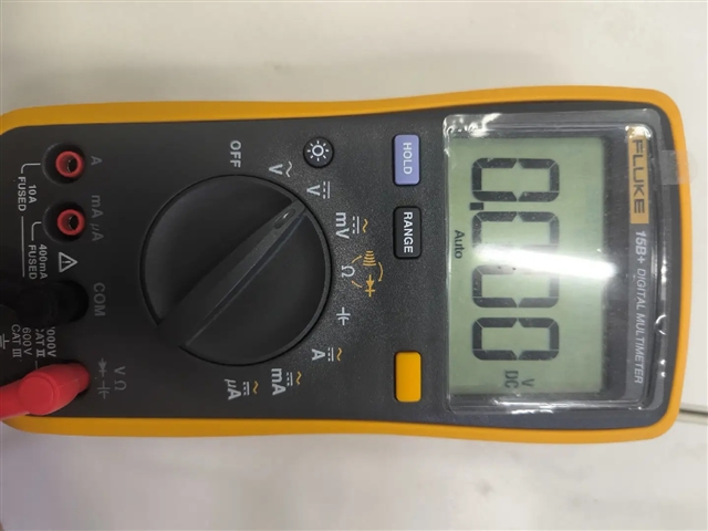
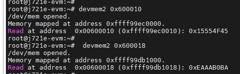
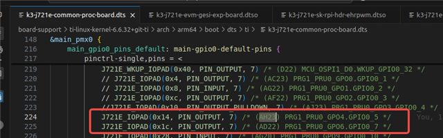
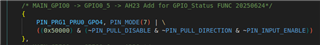
  We used the following GPIO to connect to the EN pin of LM74700. I set it as GPIO function, but when I could not successfully pull it up. And I measured that the voltage values of KL30_VBAT1 and KL30_VBAT1_HS are the

same. I have the following two problems:

1. Why can't EN pin be pulled up normally?

2. What is the function of the EN pin?

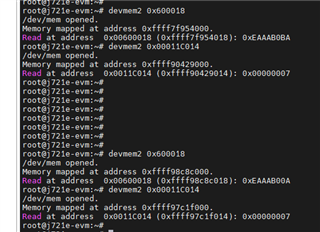
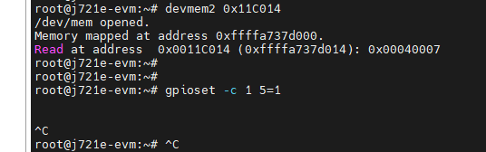
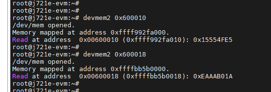
I have configured the GPIO in RTOS Pinmux and used the following functions in MCU1-0 to raise the GPIO:

Regards,

Yang

  • The GPIO should not have any issue driving the signal high or low.  Note you will have to configure GPIO as an output and drive to high/low - as internal pull resistors are not sufficient to set state.  Looping resource to help with GPIO coding review.

  • Hi Yang,

    Have you successfully ran the GPIO example from the RTOS PDK? Do you have any issues with toggling the Main and WKUP GPIO?

    Thanks,

    Neehar

  • Hi,

      I control multiple GPIO outputs in MCU1-0 at the same time, and pull them up and down every ten seconds. Other GPIOs are normal. Only AH23 reads low through the multimeter, so I want to confirm whether there are other problems?

    #define AH23_GPIO0_5_OUT    (5)
    #define AD22_GPIO0_7_OUT    (7)
    #define Y26_GPIO0_83_OUT    (83)
    #define U29_GPIO0_91_OUT    (91)
    #define U25_GPIO0_92_OUT    (92)
    #define T23_GPIO0_96_OUT    (96)
    #define R23_GPIO0_95_OUT    (95)
    #define U6_GPIO1_29_OUT     (29)
    
    void GPIO_FUNC_OUT_Test(void)
    {
        static uint32_t GPIO_status = 0;
        if(0 == GPIO_status)
        {
            GPIO_status = 1;
        }
        else
        {
            GPIO_status = 0;
        }
    
        GPIOPinWrite_v0(CSL_GPIO0_BASE, 4, GPIO_status);
    
        GPIOPinWrite_v0(CSL_GPIO0_BASE, AH23_GPIO0_5_OUT, GPIO_status);
        GPIOPinWrite_v0(CSL_GPIO0_BASE, AD22_GPIO0_7_OUT, GPIO_status);
        GPIOPinWrite_v0(CSL_GPIO0_BASE, Y26_GPIO0_83_OUT, GPIO_status);
        GPIOPinWrite_v0(CSL_GPIO0_BASE, U29_GPIO0_91_OUT, GPIO_status);
        GPIOPinWrite_v0(CSL_GPIO0_BASE, U25_GPIO0_92_OUT, GPIO_status);
        GPIOPinWrite_v0(CSL_GPIO0_BASE, T23_GPIO0_96_OUT, GPIO_status);
        GPIOPinWrite_v0(CSL_GPIO0_BASE, R23_GPIO0_95_OUT, GPIO_status);
        GPIOPinWrite_v0(CSL_GPIO1_BASE, U6_GPIO1_29_OUT, GPIO_status);
        App_printf("==========GPIO_FUNC_OUT_Test Done==============\n");
    }

    Regards,

    Yang

  • Note you do have a resistor divider on your enable signal (2.2K resistor and 10K resistor).  If the IO output is 3.3v, then then the voltage at enable pin will only be about 2.7V.  That is very close to the thresholds for the LM74700

  • Hi,

      During my testing here, the voltage value consistently remains at 0V, regardless of whether I configure it in RTOS or Linux, and even after performing a pull-

    up operation, it still remains at 0V.

    Regards,

    Yang

  • Hi Yang,

    Can you read the value of the padconfig register and provide the dump? 

    Thanks,

    Neehar

  • Hi,

      Actually, I have already sent the register values for AH23 before.

    Regards,

    Yang

  • Hi Yang,

    Could you please test with Padconfig register set to 0x00040007?

    Is this the only GPIO pin you have issues toggling?

    Note you will have to configure GPIO as an output and drive to high/low - as internal pull resistors are not sufficient to set state.

    Additionally, can you provide a dump of the GPIO dir register? Have you configured the GPIO as input or output?

    Thanks,

    Neehar

  • Hi,

      I set the register value to 0x00040007 and then used the command in the diagram to pull it up, but its voltage value is still 0V.

      I have tried configuring PINMUX to output a high level before, but its voltage value is still 0V.

    Regards,

    Yang

  • Hi Yang,

      I have tried configuring PINMUX to output a high level before, but its voltage value is still 0V.

    Although you have set the Pinmux output to level high, you will also have to configure the GPIO pin direction using the GPIO_DIR01 register.

    The physical address for GPIO_DIR01 is 0x0060 0010.

    Thanks,

    Neehar

  • Hi,

      You are right, when I manually modify the stored value, I can detect that the voltage is pulled up to 3.3V, but I want to know why configuring GPIO as output in Pinmux

    or device tree does not take effect? Did you not successfully modify these two registers?

    I simultaneously modified the GPIO of AH23 and AD22 for comparison:

    devmem2 0x600010 w 0x15554F45

    devmem2 0x600018 w 0xEAAAB0BA


    Regards,

    Yang

  • Hi Yang,

    but I want to know why configuring GPIO as output in Pinmux

    or device tree does not take effect? Did you not successfully modify these two registers?

    When setting the pinmux in the device tree as you have shown, it will only update the PADCONFIG register for the pad or pin. You have to also update the GPIO module registers to ensure the GPIO module is aware if the pin is input or output. There will be some default values for the GPIO direction register which may be why it did not previously work for specifically only AH23.

    Thanks,

    Neehar