Part Number: AM62L-PROCESSOR-SDK
Other Parts Discussed in Thread: TPS65214, TPS65215
Tool/software:
Dear TI Community,
We are currently working with the TPS65214 PMIC on our custom AM62L3-based board. The PMIC is powered with a 5V input, and we are using GPIO0 (pin number 105) as the interrupt line connected to the SoC.
While configuring the PMIC interrupt, I initially tried various IRQ trigger types, but encountered the following issues:
-
Using trigger types like
IRQ_TYPE_LEVEL_HIGHorIRQ_TYPE_EDGE_RISINGled to errors during IRQ request. -
However, setting the interrupt type to
IRQ_TYPE_EDGE_FALLINGresolved the IRQ request error.
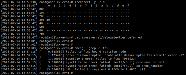
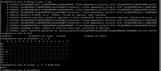
That said, once the PMIC driver starts probing with IRQ_TYPE_EDGE_FALLING, I encounter different probing errors related to other interfaces that are not seen when the PMIC is disabled. Could you please clarify why this behavior might occur? Is there any known issue or specific requirement when configuring TPS65214 interrupts on AM62L3?
Additionally, I observed the following during boot:
-
Normally, our GPIO pin (interrupt pin 105) belongs to the main_gpio0 controller.
-
However, after probing the PMIC, the system detects one additional
gpiochip(gpiochip1), which corresponds to the PMIC GPIOs.
Is this behavior expected? Does the TPS65214 PMIC driver register its own gpiochip for PMIC GPIOs by default, even if the IRQ line is connected to the SoC's main GPIO controller?
FYR: 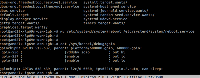
&wkup_i2c0 {
        clock-frequency = <400000>;
        pinctrl-names = "default";
        pinctrl-0 = <&wkup_i2c0_pins_default>;
        status = "okay";

        tps65214: pmic@30 {
                compatible = "ti,tps65214";
                reg = <0x30>;

                pinctrl-names = "default";
                pinctrl-0 = <&pmic_irq_pins_default>;
                interrupt-parent = <&main_gpio0>;
                interrupts = <105 IRQ_TYPE_EDGE_FALLING>;
                ti,power-button;

                buck1-supply = <&vmain_pd>;
                buck2-supply = <&vmain_pd>;
                buck3-supply = <&vmain_pd>;
                ldo1-supply = <&vmain_pd>;
                ldo2-supply = <&vmain_pd>;

                regulators {
                        buck1_reg: buck1 {
                                regulator-name = "VDD_CORE";
                                regulator-min-microvolt = <750000>;
                                regulator-max-microvolt = <750000>;
                                regulator-always-on;
                                regulator-boot-on;
                        };

                        buck2_reg: buck2 {
                                regulator-name = "DVDD_1V8";
                                regulator-min-microvolt = <1800000>;
                                regulator-max-microvolt = <1800000>;
                                regulator-always-on;
                                regulator-boot-on;
                        };

                        buck3_reg: buck3 {
                                regulator-name = "VDD_LPDDR4";
                                regulator-min-microvolt = <1100000>;
                                regulator-max-microvolt = <1100000>;
                                regulator-always-on;
                                regulator-boot-on;
                        };

                        ldo1_reg: ldo1 {
                                regulator-name = "VDD_1V8";
                                regulator-min-microvolt = <1800000>;
                                regulator-max-microvolt = <1800000>;
                                regulator-always-on;
                                regulator-boot-on;
                        };

                        ldo2_reg: ldo2 {
                                regulator-name = "VDDA_V75";
                                regulator-min-microvolt = <750000>;
                                regulator-max-microvolt = <750000>;
                                regulator-always-on;
                                regulator-boot-on;
                        };
                };
        };
};
Regards,
Dheeraj K