This thread has been locked.

If you have a related question, please click the "Ask a related question" button in the top right corner. The newly created question will be automatically linked to this question.

SK-TDA4VM: Routing MCAN5 and MCAN9 IRQ to MCU1_0

Part Number: SK-TDA4VM

Tool/software:

Hy,

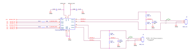
I am using the SDK: rtos-09_02_00_05 on a custom board that has the same schematic like the SK-TDA4VM (MCU_MCAN0, MCAN0, MCAN5 and MCAN9). As example I am following the pdk_jacinto_09_02_00_30/packages/ti/csl/example/mcan/mcanEvmLoopback/mcan_evm_loopback_app_main_k3.c source code.

I want to route the MCAN5 and MCAN9 IR to the MCU1_0 R5F processor. For configuring main MCAN IRQ I am using the following code:

static int32_t MCAN_CfgIrqRouterMain2Mcu(uint32_t devId, uint32_t offset, uint32_t intNum)
{
    int32_t retVal;
    struct tisci_msg_rm_irq_set_req     rmIrqReq;
    struct tisci_msg_rm_irq_set_resp    rmIrqResp;

    rmIrqReq.valid_params           = TISCI_MSG_VALUE_RM_DST_ID_VALID;
    rmIrqReq.valid_params          |= TISCI_MSG_VALUE_RM_DST_HOST_IRQ_VALID;
    rmIrqReq.src_id                 = devId;
    rmIrqReq.global_event           = 0U;
    rmIrqReq.src_index              = 1U; /* mcanss_mcan_lvl_int Line 0 */
    rmIrqReq.dst_id                 = TISCI_DEV_MCU_R5FSS0_CORE0;
    rmIrqReq.dst_host_irq           = intNum;
    rmIrqReq.ia_id                  = 0U;
    rmIrqReq.vint                   = 0U;
    rmIrqReq.vint_status_bit_index  = 0U;
    rmIrqReq.secondary_host         = TISCI_MSG_VALUE_RM_UNUSED_SECONDARY_HOST;
    retVal = Sciclient_rmIrqSet(&rmIrqReq, &rmIrqResp, SCICLIENT_SERVICE_WAIT_FOREVER);
    if(CSL_PASS != retVal)
    {
        uart_write(DEBUG_UART, "Error in SciClient Interrupt Params Configuration!!!");
        snprintf(buffer, sizeof(buffer), "offset: %d \n", offset);
        uart_write(DEBUG_UART, buffer);
    }
    else
    {
        snprintf(buffer, sizeof(buffer), 
                "SciClient Interrupt Params Configuration passed for intNum: %08X \n", intNum);
        uart_write(DEBUG_UART, buffer);
    }
    return retVal;
}

And for registering the interrupt:

static int32_t MCAN_regiterISR(uint32_t intNum, void f(uintptr_t))
{
   int32_t configStatus = STW_SOK;
    OsalRegisterIntrParams_t    intrPrms;
    OsalInterruptRetCode_e      osalRetVal;
    HwiP_Handle                 hwiHandle = NULL;

    /* Enable CPU Interrupts and register ISR */
    Osal_RegisterInterrupt_initParams(&intrPrms);
    /* Populate the interrupt parameters */
    intrPrms.corepacConfig.arg              = (uintptr_t) NULL;
    intrPrms.corepacConfig.isrRoutine       = f;
    intrPrms.corepacConfig.priority         = 1U;
    intrPrms.corepacConfig.corepacEventNum  = 0U;
    intrPrms.corepacConfig.intVecNum        = intNum;

    /* Register interrupts */
    osalRetVal = Osal_RegisterInterrupt(&intrPrms, &hwiHandle);
    if(OSAL_INT_SUCCESS != osalRetVal)
    {
        configStatus = CSL_EFAIL;
        uart_write(DEBUG_UART, "Error in registering ISR!!!");
    }
    return configStatus;
}

My aim is to test the external loopback mode between MCAN5 and MCAN9. As rmIrqReq.src_id I am configuring TISCI_DEV_MCAN5 and TISCI_DEV_MCAN9, and src_index =1 but I don't know for rmIrqReq.dst_host_irq what should I configure?  The dst_id is TISCI_DEV_MCU_R5FSS0_CORE0 for both.

Regards,
Tamas

  • Hello,

    As rmIrqReq.src_id I am configuring TISCI_DEV_MCAN5 and TISCI_DEV_MCAN9, and src_index =1

    MCAN5 and MCAN9 both peripherals are connecting to MAIN2MCU LVL interrupt router.

    From MAIN2MCU LVL interrupt router it is going to MCU1_0 and MCU1_1 cores

    https://software-dl.ti.com/tisci/esd/latest/5_soc_doc/j721e/interrupt_cfg.html#main2mcu-lvl-intrtr0-interrupt-router-output-destinations

    so for your irq number you can select and use 160-223 any number .

    Only constraint is you should not do re registration of same irq number which will cause failure .Use 2 different irq numbers between range of 160-223 and ensure the number is not used elsewhere.

    Regards

    Tarun Mukesh

  • Hello Tarun,

    Thanks, that was very helpful. I have one more question: when sending a message, in the MCAN_selectIntrLine() function, should the third parameter be set to the interrupt line number that I configured in the range 160–223?

    #define MCAN5_INT0         CSLR_MCU_R5FSS0_CORE0_INTR_MAIN2MCU_LVL_INTRTR0_OUTL_2
    
    /* Select Interrupt Line for Tx CAN instance */
    MCAN_selectIntrLine(baseAddrTx,
                        MCAN_INTR_MASK_ALL,
                        MCAN5_INT0);


    Regards,
    Tamas

  • Hello,

    have one more question: when sending a message, in the MCAN_selectIntrLine() function, should the third parameter be set to the interrupt line number that I configured in the range 160–223

    No. This line number is not irq number.

    The line number here represents multiple interrupt lines present in MCAN which is 0 and 1.

    Regards

    Tarun Mukesh

  • Hello,

    Thanks for the clarification. Currently, the interrupt is triggered, but the MCAN_INTR_SRC_TRANS_COMPLETE bit is not set in the interrupt status register.The MCAN_IR register holds the value 0x0B800000, which corresponds to the following bits being set: EWE, BOE, WDIE, and PEDE.

    Notably, the interrupt is raised immediately after attempting to send an MCAN message.

    Regards,
    Tamas

  • Hello,

    I will be out of office next 2 days .Please expect delay in response.

    Regards

    Tarun Mukesh

  • Hello Tamas,

    The CAN controller has entered the Bus Off state. This usually happens when too many errors have occurred on the bus such as dominant/recessive errors, faulty wiring, grounding problems, or termination issues.

    But one more observation i have here is A protocol violation has been detected. This occurs only if you have framing, CRC, stuff error, etc...

    The MCAN is not able to send the message successfully. Error and protocol violations prevent a successful transmission, leading to Bus Off, so the transmission complete  interrupt is not set.

    The system will remain in Bus Off until cleared by software or hardware reset, depending on MCAN configuration.

    The CAN bus or connection may be physically faulty or misconfigured bit rates.

    You can also check Physical Layer:

    Ensure correct bus wiring, termination resistors, and no floating or short-circuited lines.

    Confirm Bitrate Matching: Both MCAN and all other nodes must use the same bitrate settings.

    Ensure correct MCAN initialization sequence and timings. Verify sample point and other timing parameters.

    we have recently published CAN debug guide ,you can refer https://www.ti.com/lit/an/spradp4/spradp4.pdf

    Regards

    Tarun Mukesh

  • Hello Tarun,

    This occurs only if you have framing, CRC, stuff error, etc...

    Okay, in the mcan_evm_loopback_app_main_k3.c I do not see any setting regarding to the CRC. Maybe should be some issues when I try to create my own txMsg. I am creating it in the following way:

    txMsg->id = (uint32_t)((uint32_t)(0x4U) << 18U);
    txMsg->rtr = 0U; /* Transmit Data Frame */
    txMsg->xtd = 0U; /* Transmit Standard Frame */
    txMsg->esi = 0U; /* Transmit with no error state indicator */
    txMsg->dlc = 0x1U; /* Data Length Code - This should be modified !!! */
    txMsg->brs = 0U; /* No Bit Rate Switch */
    txMsg->fdf = 0U; /* No FD Frame */
    txMsg->efc = 1U; /* FIFO Event Store */
    txMsg->mm = 0xAAU; /* Message Marker */
    txMsg->data[0] = 1;


    Is this correct? At the moment I only want to send 1 byte to see if the communication works.

    Ensure correct bus wiring, termination resistors, and no floating or short-circuited lines.

    Yes, I have checked this one, the Tx and Rx are connected to the TCAN1046 and are pulled up, the transceiver is active:

    Confirm Bitrate Matching: Both MCAN and all other nodes must use the same bitrate settings.

    Both MCAN5 and MCAN9 are set to the same bitrate configuration:

            bitTimes.nomRatePrescalar   = 0x7U;
            bitTimes.nomTimeSeg1        = 0x5U;
            bitTimes.nomTimeSeg2        = 0x2U;
            bitTimes.nomSynchJumpWidth  = 0x0U;
            bitTimes.dataRatePrescalar  = 0x1U;
            bitTimes.dataTimeSeg1       = 0x3U;
            bitTimes.dataTimeSeg2       = 0x2U;
            bitTimes.dataSynchJumpWidth = 0x0U;
     

    Ensure correct MCAN initialization sequence and timings. Verify sample point and other timing parameters.

    After each configuration and initialization I am checking the return value of the mcan pdk functions, and no error is set.

    we have recently published CAN debug guide ,you can refer

    Thank you for the guide. I’ve reviewed all the issues listed, but unfortunately, I still haven’t found a working solution.

    I suspect the problem might be with the message configuration — either it's incorrect or there’s a missing setting. Also, I haven’t found any concrete examples of how to handle the CRC calculation, which might be relevant.

    Another detail: I tested communication in polling mode, and in that case, it worked — both MCAN5 and MCAN9 were able to send their own messages. However, I haven't implemented any kind of ACK handling or retransmission logic yet. The two are connected in external loopback.

    I hope this additional information helps clarify my situation and guide further troubleshooting.

    Regards,
    Tamas  

  • Okay, in the mcan_evm_loopback_app_main_k3.c I do not see any setting regarding to the CRC. Maybe should be some issues when I try to create my own txMsg.

    You only shared half CAN frame. Why can't you use default frame format present in example?

    and also your format didn't align properly as below

    Regards

    Tarun Mukesh 

  • You only shared half CAN frame. Why can't you use default frame format present in example?

    Okay, I'm using exactly the same code as in the example, still at the first trasmission, when the interrupt kicks in the interrupt flag has the following error: 0x9800000

    enum
    {
        /**< MCAN5 Base Address */
        CAN_CONTROLLER_2 = 0x2758000UL,
        /**< MCAN9 Base Address */
        CAN_CONTROLLER_3 = 0x2798000UL    
    }can_base_address;
    
    const uint32_t can_base_address_array[] = {
        CAN_CONTROLLER_2,
        CAN_CONTROLLER_3
    };
    
    
    tatic void setConfig_CanObject(void)
    {
        for (uint8_t idx = 0U; idx < CAN_NUM_CONTROLLER; idx++)
        {
            CAN_obj[idx].CntrlId = idx;
            CAN_obj[idx].BaseAddr = can_base_address_array[idx];
        }
    }
    
    
    void CAN_HwUnitConfig(void)
    {
        MCAN_RevisionId            revId;
        uint32_t baseAddr, timeQuanta;
        int32_t  configStatus = STW_SOK;
        uint8_t  tmpVal;
        const Can_ControllerType  *canControllerCfg;
        MCAN_InitParams            initParams         = {0};
        MCAN_ConfigParams          configParams       = {0};
        MCAN_BitTimingParams       bitTimes           = {0};
        MCAN_StdMsgIDFilterElement stdFiltelem        = {0};
        MCAN_MsgRAMConfigParams    msgRAMConfigParams = {0};
        MCAN_ECCErrStatus          gMcaneccErr        = {0};
        MCAN_ProtocolStatus        protStatus         = {0};  
        
        setConfig_CanObject();
    
        /* MCAN5 out of standby */
        GPIOSetDirMode_v0(CSL_GPIO0_BASE, MCAN5_ENABLE_PIN, GPIO_DIRECTION_OUTPUT);
        GPIOPinWrite_v0(CSL_GPIO0_BASE, MCAN5_ENABLE_PIN, GPIO_PIN_LOW);
    
        /* MCAN9 out ouf standby */
        GPIOSetDirMode_v0(CSL_GPIO0_BASE, MCAN9_ENABLE_PIN, GPIO_DIRECTION_OUTPUT);
        GPIOPinWrite_v0(CSL_GPIO0_BASE, MCAN9_ENABLE_PIN, GPIO_PIN_LOW);
    
        for (uint8_t idx = MCAN5; idx < MCAN9; idx++)
        {
            baseAddr = tcht_CAN_obj[idx].BaseAddr;
            gMcanModAddr = baseAddr;
    
            else if (idx == 2U)
            {
                configStatus += MCAN_CfgIrqRouterMain2Mcu( TISCI_DEV_MCAN5, 1U, MCAN5_INT0);
                configStatus += MCAN_CfgIrqRouterMain2Mcu( TISCI_DEV_MCAN5, 2U, MCAN5_INT1);
                configStatus += MCAN_regiterISR(MCAN5_INT0, &MCANIntr4ISR);
                configStatus += MCAN_regiterISR(MCAN5_INT1, &MCANIntr5ISR);
            }
            else if (idx == 3U)
            {
                configStatus += MCAN_CfgIrqRouterMain2Mcu( TISCI_DEV_MCAN9, 1U, MCAN9_INT0);
                configStatus += MCAN_CfgIrqRouterMain2Mcu( TISCI_DEV_MCAN9, 2U, MCAN9_INT1);
                configStatus += MCAN_regiterISR(MCAN9_INT0, &MCANIntr6ISR);
                configStatus += MCAN_regiterISR(MCAN9_INT1, &MCANIntr7ISR);
            }
    
            /* Initialize MCAN Init params */
            initParams.fdMode          = 0x1U;
            initParams.brsEnable       = 0x1U;
            initParams.txpEnable       = 0x0U;
            initParams.efbi            = 0x0U;
            initParams.pxhddisable     = 0x0U;
            /* To enable automatic retransmission of the packet,
             * program initParams.darEnable to "0" */
            initParams.darEnable       = 0x1U;
            initParams.wkupReqEnable   = 0x1U;
            initParams.autoWkupEnable  = 0x1U;
            initParams.emulationEnable = 0x1U;
            initParams.emulationFAck   = 0x0U;
            initParams.clkStopFAck     = 0x0U;
            initParams.wdcPreload      = 0xFFU;
            initParams.tdcEnable       = 0x1U;
            initParams.tdcConfig.tdcf  = 0xAU;
            initParams.tdcConfig.tdco  = 0x6U;
    
            /* Initialize MCAN Config params */
            configParams.monEnable         = 0x0U;
            configParams.asmEnable         = 0x0U;
            configParams.tsPrescalar       = 0xFU;
            configParams.tsSelect          = 0x0U;
            configParams.timeoutSelect     = MCAN_TIMEOUT_SELECT_CONT;
            configParams.timeoutPreload    = 0xFFFFU;
            configParams.timeoutCntEnable  = 0x0U;
            configParams.filterConfig.rrfs = 0x1U;
            configParams.filterConfig.rrfe = 0x1U;
            configParams.filterConfig.anfe = 0x1U;
            configParams.filterConfig.anfs = 0x0U;
    
            /* Initialize bit timings
             * Configuring 1Mbps and 5Mbps as nominal and data bit-rate respectively */
            bitTimes.nomRatePrescalar   = 0x7U;
            bitTimes.nomTimeSeg1        = 0x5U;
            bitTimes.nomTimeSeg2        = 0x2U;
            bitTimes.nomSynchJumpWidth  = 0x0U;
            bitTimes.dataRatePrescalar  = 0x1U;
            bitTimes.dataTimeSeg1       = 0x3U;
            bitTimes.dataTimeSeg2       = 0x2U;
            bitTimes.dataSynchJumpWidth = 0x0U;
            
            /* Initialize Tx Buffer Config params */
            stdFiltelem.sfid2 = 0x0U;
            stdFiltelem.sfid1 = 0x4U;
            stdFiltelem.sfec  = 0x7U;
            stdFiltelem.sft   = 0x2U;
    
            /* Initialize Message RAM Sections Configuration Parameters */
            msgRAMConfigParams.flssa                = MCAN_STD_ID_FILT_START_ADDR;
            msgRAMConfigParams.lss                  = MCAN_STD_ID_FILTER_NUM;
            msgRAMConfigParams.flesa                = MCAN_EXT_ID_FILT_START_ADDR;
            msgRAMConfigParams.lse                  = MCAN_EXT_ID_FILTER_NUM;
            msgRAMConfigParams.txStartAddr          = MCAN_TX_BUFF_START_ADDR;
            msgRAMConfigParams.txBufNum             = MCAN_TX_BUFF_SIZE;
            msgRAMConfigParams.txFIFOSize           = 0U;
            msgRAMConfigParams.txBufMode            = 0U;
            msgRAMConfigParams.txBufElemSize        = MCAN_ELEM_SIZE_64BYTES;
            msgRAMConfigParams.txEventFIFOStartAddr = MCAN_TX_EVENT_START_ADDR;
            msgRAMConfigParams.txEventFIFOSize      = MCAN_TX_BUFF_SIZE;
            msgRAMConfigParams.txEventFIFOWaterMark = 3U;
            msgRAMConfigParams.rxFIFO0startAddr     = MCAN_FIFO_0_START_ADDR;
            msgRAMConfigParams.rxFIFO0size          = MCAN_FIFO_0_NUM;
            msgRAMConfigParams.rxFIFO0waterMark     = 3U;
            msgRAMConfigParams.rxFIFO0OpMode        = 0U; /* Don't block if the fifo is full */
            msgRAMConfigParams.rxFIFO1startAddr     = MCAN_FIFO_1_START_ADDR;
            msgRAMConfigParams.rxFIFO1size          = MCAN_FIFO_1_NUM;
            msgRAMConfigParams.rxFIFO1waterMark     = 3U;
            msgRAMConfigParams.rxFIFO1OpMode        = 0U; /* Don't block if the fifo is full */
            msgRAMConfigParams.rxBufStartAddr       = MCAN_RX_BUFF_START_ADDR;
            msgRAMConfigParams.rxBufElemSize        = MCAN_ELEM_SIZE_64BYTES;
            msgRAMConfigParams.rxFIFO0ElemSize      = MCAN_ELEM_SIZE_64BYTES;
            msgRAMConfigParams.rxFIFO1ElemSize      = MCAN_ELEM_SIZE_64BYTES;
    
            MCAN_isFDOpEnable(baseAddr);
            /* Reseting the CAN module */
            MCAN_reset(baseAddr);
            while (MCAN_isInReset(baseAddr) == (uint32_t)TRUE)
            {
            }
            /* Set operation mode */
            MCAN_setOpMode(baseAddr, MCAN_OPERATION_MODE_SW_INIT);
            /* Checking CAN module status */
            while(FALSE == MCAN_isMemInitDone(baseAddr))
            {}
            /* Initialize CAN controller */
            configStatus = MCAN_init(baseAddr, &initParams);
            if (configStatus != STW_SOK)
            {
                snprintf(buffer, sizeof(buffer), "DEBUG_INFO(CAN): "
                                    "MCAN Initialization failed for baseAddr: 0x%08X\n", baseAddr);
                uart_write(DEBUG_UART, buffer);
                return;
            }
            /* Configure the CAN controller */
            configStatus = MCAN_config(baseAddr, &configParams);
            if (configStatus != STW_SOK)
            {
                snprintf(buffer, sizeof(buffer), "DEBUG_INFO(CAN): "
                                    "MCAN Configuration failed for baseAddr: 0x%08X\n", baseAddr);
                uart_write(DEBUG_UART, buffer);
                return;
            }
            /* Configure the CAN bit timing */
            configStatus = MCAN_setBitTime(baseAddr, &bitTimes);
            if (configStatus != STW_SOK)
            {
                snprintf(buffer, sizeof(buffer), "DEBUG_INFO(CAN): "
                                    "MCAN Bit Timing Configuration failed for baseAddr: 0x%08X\n", baseAddr);
                uart_write(DEBUG_UART, buffer);
                return;
            }
            /* Configuring the CAN Extended ID mask */
            configStatus = MCAN_setExtIDAndMask(baseAddr, 0x1FFFFFFFU);
            if( configStatus != STW_SOK)
            {
                snprintf(buffer, sizeof(buffer), "DEBUG_INFO(CAN): "
                                    "MCAN Extended ID Mask Configuration failed for baseAddr: 0x%08X\n", baseAddr);
                uart_write(DEBUG_UART, buffer);
                return;
            }
            /* Configure Message RAM Sections */
            configStatus = MCAN_msgRAMConfig(baseAddr, &msgRAMConfigParams);
            if (configStatus != STW_SOK)
            {
                snprintf(buffer, sizeof(buffer), "DEBUG_INFO(CAN): "
                                    "MCAN Message RAM Configuration failed for baseAddr: 0x%08X\n", baseAddr);
                uart_write(DEBUG_UART, buffer);
                return;
            }
            /* Configure Standard ID filter element */
            MCAN_addStdMsgIDFilter(baseAddr, 0U, &stdFiltelem);
    
            MCAN_setOpMode(baseAddr, MCAN_OPERATION_MODE_NORMAL);
            while (MCAN_OPERATION_MODE_NORMAL != MCAN_getOpMode(baseAddr))
            {
                MCAN_setOpMode(baseAddr, MCAN_OPERATION_MODE_NORMAL);
            }
    
            snprintf(buffer, sizeof(buffer), 
                        "------- Checking MCAN protocol for idx: %d ----------\n", idx );
            uart_write(DEBUG_UART, buffer);
    
            MCAN_getProtocolStatus(baseAddr, &protStatus);
            /* Checking for Errors */
            if (((MCAN_ERR_CODE_NO_ERROR == protStatus.lastErrCode) ||
                    (MCAN_ERR_CODE_NO_CHANGE == protStatus.lastErrCode)) &&
                ((MCAN_ERR_CODE_NO_ERROR == protStatus.dlec) ||
                    (MCAN_ERR_CODE_NO_CHANGE == protStatus.dlec)) &&
                (0U == protStatus.pxe))
            {
                uart_write(DEBUG_UART, "MCAN Protocol Status OK\n");
            }
            else
            {
                snprintf(buffer, sizeof(buffer),
                "Error in transmission for address :0x%08X\n", baseAddr);
                uart_write(DEBUG_UART, buffer);
            }
    
            MCAN_lpbkModeEnable(baseAddr, MCAN_LPBK_MODE_EXTERNAL, (uint32_t)TRUE);
        }
    }
    
    static void MCAN_initTxBufElement(MCAN_TxBufElement *txMsg)
    {
        uint32_t loopCnt = 0;
        if (txMsg != NULL)
        {
            txMsg->id = (uint32_t)((uint32_t)(0x4U) << 18U);
            txMsg->rtr = 0U; /* Transmit Data Frame */
            txMsg->xtd = 0U; /* Transmit Standard Frame */
            txMsg->esi = 0U; /* Transmit with no error state indicator */
            txMsg->dlc = 0xFU; /* Data Length Code - This should be modified !!! */
            txMsg->brs = 0U; /* No Bit Rate Switch */
            txMsg->fdf = 0U; /* No FD Frame */
            txMsg->efc = 1U; /* FIFO Event Store */
            txMsg->mm = 0xAAU; /* Message Marker */
            for (loopCnt = 0; loopCnt < MCAN_MAX_PAYLOAD_BYTES; loopCnt++)
            {
                txMsg->data[loopCnt] = loopCnt;
            }
        }
    
    }
    
    
    void CAN_lpbk(uint8_t can_tx_idx, uint8_t can_rx_idx)
    {
        int32_t  testStatus = CSL_PASS;
        MCAN_ProtocolStatus protStatus;
        MCAN_RxBufElement    rxMsg;
        MCAN_RxNewDataStatus newDataStatus;
        MCAN_ErrCntStatus    errCounter;
        uint32_t loopCnt, chkCnt, errFlag;
        MCAN_TxBufElement txMsg;
        
        /* Initialize Tx message structure */
        MCAN_initTxBufElement(&txMsg);
    
        uint32_t baseAddrTx = CAN_obj[can_tx_idx].BaseAddr;
        uint32_t baseAddrRx = CAN_obj[can_rx_idx].BaseAddr;
    
        /* Enable Transmission Interrupts for Tx CAN instance */
        MCAN_enableIntr(baseAddrTx, MCAN_INTR_MASK_ALL , (uint32_t)TRUE);
        MCAN_enableIntr(baseAddrTx, MCAN_INTR_SRC_RES_ADDR_ACCESS, (uint32_t)FALSE);
        
        /* Enable Transmission Interrupts for Rx CAN instance */
        MCAN_enableIntr(baseAddrRx, MCAN_INTR_MASK_ALL, (uint32_t)TRUE);
        MCAN_enableIntr(baseAddrRx, MCAN_INTR_SRC_RES_ADDR_ACCESS, (uint32_t)FALSE);
    
        /* Select Interrupt Line for Tx CAN instance */
        MCAN_selectIntrLine(baseAddrTx,
                            MCAN_INTR_MASK_ALL,
                            MCAN_INTR_LINE_NUM_1);
    
        /* Select Interrupt Line for Rx CAN instance */
        MCAN_selectIntrLine(baseAddrRx,
                            MCAN_INTR_MASK_ALL,
                            MCAN_INTR_LINE_NUM_1);
    
    
        /* Enable Interrupt Line for Tx CAN instance */
        MCAN_enableIntrLine(baseAddrTx,
                            MCAN_INTR_LINE_NUM_1,
                            1U);
    
        /* Enable Interrupt Line for Rx CAN instance*/
        MCAN_enableIntrLine(baseAddrRx,
                            MCAN_INTR_LINE_NUM_1,
                            1U);
    
        /* Enable Transmission interrupt */
        testStatus = MCAN_txBufTransIntrEnable(baseAddrTx,
                                               1U,
                                               (uint32_t)TRUE);
    
        if (CSL_PASS != testStatus)
        {
            uart_write(DEBUG_UART,"\n  Error in enabling buffer Transmit interrupt...\n");
            return;
        }
        else
        {
            for(loopCnt = 1U; loopCnt < 16U; loopCnt++)
            {
                txMsg.dlc =  loopCnt;
                
                MCAN_writeMsgRam(baseAddrTx, MCAN_MEM_TYPE_BUF, 1U, &txMsg);
    
                /* Add request for transmission */
                testStatus = MCAN_txBufAddReq(baseAddrTx, 1U);
                if (STW_SOK != testStatus)
                {
                    uart_write(DEBUG_UART,"\n  Error in Adding Transmission Request...\n");
                    return;
                }
    
                MCAN_ErrCntStatus errCntStatus;
                MCAN_getErrCounters(baseAddrTx, &errCntStatus);
                snprintf(buffer, sizeof(buffer), "DEBUG_INFO(CAN): "
                                        "MCAN TEC: 0x%08X\n", errCntStatus.transErrLogCnt);
                uart_write(DEBUG_UART, buffer);
                snprintf(buffer, sizeof(buffer), "DEBUG_INFO(CAN): "
                                        "MCAN REC: 0x%08X\n", errCntStatus.recErrCnt);
                uart_write(DEBUG_UART, buffer);
                snprintf(buffer, sizeof(buffer), "DEBUG_INFO(CAN): "
                                        "MCAN RP: 0x%08X\n", errCntStatus.rpStatus);
                uart_write(DEBUG_UART, buffer);
                snprintf(buffer, sizeof(buffer), "DEBUG_INFO(CAN): "
                                        "MCAN CAN_ERR_LOG_CNT: 0x%08X\n", errCntStatus.canErrLogCnt);
                uart_write(DEBUG_UART, buffer);
    
                while (McanIsrIntr5Flag)
                {}
                McanIsrIntr5Flag = 1U;
                MCAN_getProtocolStatus(baseAddrTx, &protStatus);
                /* Checking for Errors */
                if (((MCAN_ERR_CODE_NO_ERROR == protStatus.lastErrCode) ||
                        (MCAN_ERR_CODE_NO_CHANGE == protStatus.lastErrCode)) &&
                    ((MCAN_ERR_CODE_NO_ERROR == protStatus.dlec) ||
                        (MCAN_ERR_CODE_NO_CHANGE == protStatus.dlec)) &&
                    (0U == protStatus.pxe))
                {
                    snprintf(buffer, sizeof(buffer),
                        "\nMessage successfully transferred with payload Bytes:%d",
                        txMsg.dlc);
                    uart_write(DEBUG_UART, buffer);
                }
                else
                {
                    snprintf(buffer, sizeof(buffer),
                            "\nError in transmission with payload Bytes:%d", txMsg.dlc);
                    uart_write(DEBUG_UART, buffer);
    
                    testStatus = CSL_EFAIL;
                }
    
                while (McanIsrIntr9Flag_lpbk)
                {}
                McanIsrIntr9Flag_lpbk = 1U;
                /* Checking for Errors */
                MCAN_getErrCounters(baseAddrRx, &errCounter);
                if ((0U == errCounter.recErrCnt) &&
                    (0U == errCounter.canErrLogCnt))
                {
                    MCAN_getNewDataStatus(baseAddrRx, &newDataStatus);
                    MCAN_clearNewDataStatus(baseAddrRx, &newDataStatus);
                    MCAN_readMsgRam(baseAddrRx, MCAN_MEM_TYPE_BUF, 0U, 0U, &rxMsg);
                    errFlag = 0U;
                    for (chkCnt = 0U; chkCnt < canDataSize[rxMsg.dlc]; chkCnt++)
                    {
                        if (txMsg.data[chkCnt] != rxMsg.data[chkCnt])
                        {
                            errFlag = 1U;
                            break;
                        }
                    }
    
                    if (0U == errFlag)
                    {
                        snprintf(buffer, sizeof(buffer),
                            "\nMessage successfully received with payload Bytes: %d",
                            rxMsg.dlc);
                        uart_write(DEBUG_UART, buffer);
                    }
                    else
                    {
                        snprintf(buffer, sizeof(buffer),
                             "\nWrong data received in message with payload Bytes: %d", rxMsg.dlc);
                        uart_write(DEBUG_UART, buffer);
                        testStatus = CSL_EFAIL;
                    }
                }
                else
                {
                    snprintf(buffer, sizeof(buffer),"\nError in reception with payload Bytes:%d",txMsg.dlc);
                    uart_write(DEBUG_UART, buffer);
                    testStatus = CSL_EFAIL;
                }
            }
        }   
    }  

    Here is my code. I am doing the same thing that is done in the example application.

    Regards,
    Tamas

  • Hello,

    I believe you have problem with your interrupt registration and usage only.

    /* Enable the MCAN interrupts */
    MCAN_enableIntr(baseAddr, MCAN_INTR_MASK, 1U);
    MCAN_selectIntrLine(baseAddr, MCAN_INTR_MASK, MCAN_INTR_LINE_NUM_0);
    MCAN_enableIntrLine(baseAddr, MCAN_INTR_LINE_NUM_0, 1U);
    Try using interrupt line number 0  .
    In Interrupt router code MCAN_CfgIrqRouterMain2Mcu you are using line  0    rmIrqReq.src_index              = 1U; /* mcanss_mcan_lvl_int Line 0 */ 
    But in configuration you are using line 1 that is wrong.
    What is value of this MCAN5_INT0 , MCAN5_INT1, MCAN9_INT0 , MCAN9_INT1 ?
    What is purpose of offset in this API static int32_t MCAN_CfgIrqRouterMain2Mcu(uint32_t devId, uint32_t offset, uint32_t intNum) ? which is not used in API at all.
    Regards
    Tarun Mukesh
  • Hello,

    What is value of this MCAN5_INT0 , MCAN5_INT1, MCAN9_INT0 , MCAN9_INT1 ?

    These are the values:

    #define MCAN0_INT0         CSLR_MCU_R5FSS0_CORE0_INTR_MAIN2MCU_LVL_INTRTR0_OUTL_0
    #define MCAN0_INT1         CSLR_MCU_R5FSS0_CORE0_INTR_MAIN2MCU_LVL_INTRTR0_OUTL_1
    #define MCAN5_INT0         CSLR_MCU_R5FSS0_CORE0_INTR_MAIN2MCU_LVL_INTRTR0_OUTL_2
    #define MCAN5_INT1         CSLR_MCU_R5FSS0_CORE0_INTR_MAIN2MCU_LVL_INTRTR0_OUTL_3
    #define MCAN9_INT0         CSLR_MCU_R5FSS0_CORE0_INTR_MAIN2MCU_LVL_INTRTR0_OUTL_4
    #define MCAN9_INT1         CSLR_MCU_R5FSS0_CORE0_INTR_MAIN2MCU_LVL_INTRTR0_OUTL_5

    What is purpose of offset in this API static int32_t MCAN_CfgIrqRouterMain2Mcu(uint32_t devId, uint32_t offset, uint32_t intNum) ? which is not used in API at all.

    I am little bit new with the interrupt routing logic, and I thought that first I have to configure the source and the destination of the interrupt, and after I need to register the ISR for that input line. Am I right?

    MCAN_enableIntr(baseAddr, MCAN_INTR_MASK, 1U);
    MCAN_selectIntrLine(baseAddr, MCAN_INTR_MASK, MCAN_INTR_LINE_NUM_0);
    MCAN_enableIntrLine(baseAddr, MCAN_INTR_LINE_NUM_0, 1U);

    So when I configure the route Main2Mcu for the offset index I need to set to 0? Why are two interrupts (in some cases 3) for one device?

    Regards,
    Tamas

  • Hello Tamas,

    I am little bit new with the interrupt routing logic, and I thought that first I have to configure the source and the destination of the interrupt, and after I need to register the ISR for that input line. Am I right?

    Please refer MCAN section in TRM document for more details www.ti.com/.../spruil1 .

    I am little bit new with the interrupt routing logic, and I thought that first I have to configure the source and the destination of the interrupt, and after I need to register the ISR for that input line. Am I right?

    This is correct but your configuration, routings are not matching.

    The source and destination of interrupt is different and the interrupt line is different.

    In MCAN we have 2 interrupt lines to use 0 and 1 as i stated above. This corresponding interrupt line will have source index

    rmIrqReq.src_index = 1U; /* mcanss_mcan_lvl_int Line 0 */

    for this you have to use

    MCAN_selectIntrLine(baseAddr, MCAN_INTR_MASK, MCAN_INTR_LINE_NUM_0);

    The above way is correct.

    but you are using

    rmIrqReq.src_index = 1U; /* mcanss_mcan_lvl_int Line 0 */

    for this you have to use

    MCAN_selectIntrLine(baseAddr, MCAN_INTR_MASK, MCAN_INTR_LINE_NUM_1);

    This is wrong.

    What is purpose of offset in this API static int32_t MCAN_CfgIrqRouterMain2Mcu(uint32_t devId, uint32_t offset, uint32_t intNum) ? which is not used in API at all.

    In the entire API definition you are not using offset argument  other than printing what is its purpose. I recommend you to understand how interrupt routing works completely and then proceed with development otherwise it will be really tough to identify the problem.

    You can do it the same way you did for MCAN0. 

    Regards

    Tarun Mukesh

  • Hello Tarun

    MCAN_selectIntrLine(baseAddr, MCAN_INTR_MASK, MCAN_INTR_LINE_NUM_1);

    The main reason I’m using this specific interrupt line number is that when I set it to MCAN_selectIntrLine(baseAddr, MCAN_INTR_MASK, MCAN_INTR_LINE_NUM_1), the interrupt does not trigger after calling MCAN_writeMsgRam.

    To clarify the setup step-by-step:

    1. IRQ Router Configuration:
      I configure the IRQ Router (Main2MCU) as follows:

      • src_id: TISCI_DEV_MCAN0

      • src_index: 1

      • dts_id: TISCI_DEV_MCU_R5FSS0_CORE0

      • dst_host_irq: MCAN5_INT0 (CSLR_MCU_R5FSS0_CORE0_INTR_MAIN2MCU_LVL_INTRTR0_OUTL_2)

    2. ISR Registration:
      I register the ISR for MCAN5_INT0. The callback function executes the following:


        uint32_t intrStatus;
        gMcanModAddr = CAN_obj[2].BaseAddr;
        uart_write(DEBUG_UART, "--------------------------------\n");
        snprintf(buffer, sizeof(buffer), "Address: %8X\n", gMcanModAddr);
        uart_write(DEBUG_UART, buffer);
    
        intrStatus = MCAN_getIntrStatus(gMcanModAddr);
        MCAN_clearIntrStatus(gMcanModAddr, intrStatus);
        if (MCAN_INTR_SRC_TRANS_COMPLETE ==
            (intrStatus & MCAN_INTR_SRC_TRANS_COMPLETE))
        {
            McanIsrIntr5Flag = 0U;
        }
    
        if (MCAN_INTR_SRC_DEDICATED_RX_BUFF_MSG ==
            (intrStatus & MCAN_INTR_SRC_DEDICATED_RX_BUFF_MSG))
        {
            McanIsrIntr5Flag = 0U;
            McanIsrIntr5Flag_lpbk = 0U;
        }

    I included debug prints to verify whether the interrupt is received.

    However, no output appears on the console, which suggests that the interrupt is not being triggered.

    3. MCAN Initialization:
    The MCAN is properly configured and initialized.

    4. Message Transmission:
    I'm sending a message from MCAN5 to MCAN9.

    MCAN_enableIntr(baseAddrTx, MCAN_INTR_MASK , (uint32_t)TRUE);
    MCAN_enableIntr(baseAddrTx, MCAN_INTR_SRC_RES_ADDR_ACCESS, (uint32_t)FALSE);
    MCAN_selectIntrLine(baseAddrTx,MCAN_INTR_MASK,MCAN_INTR_LINE_NUM_0);
    MCAN_enableIntrLine(baseAddrTx,MCAN_INTR_LINE_NUM_0,1U);

    By the way, how is the ACK managed? I didn't see any ACK being transmitted in the example code.

    Regards,
    Tamas

  • In the meantime, just one thing to add: I am now receiving the interrupt after sending the message, but the MCAN_IR register still shows the BO and EW status bits set.

    Regards,
    Tamas

  • Hello,

    By the way, how is the ACK managed? I didn't see any ACK being transmitted in the example code.

    ACK will not be transmitted , it is sent by CAN controller on the receiver side. That is CAN's protocol mechanism.

    In the meantime, just one thing to add: I am now receiving the interrupt after sending the message, but the MCAN_IR register still shows the BO and EW status bits set.

    You are receiving interrupt after sending message means interrupt routing is done successfully but you have some error in the system which is driving to bus off.

    MCAN_IR will be set once if you get an error and will not be cleared unless you write 0 into it or reset. what is the status of MCAN_PSR and MCAN_ECR ?

    Regards

    Tarun Mukesh

  • Hello,

    MCAN_IR will be set once if you get an error and will not be cleared unless you write 0 into it or reset. what is the status of MCAN_PSR and MCAN_ECR ?

    The MCAN_PSR: 0x0000076D and MCAN_ECR: 0x00110088

    Regards,
    Tamas

  • The MCAN_PSR: 0x0000076D and MCAN_ECR: 0x00110088

    PSR register is showing as Bit 0 error and TEC count is at 136 not reached 255 for bus off .

    Regards

    Tarun Mukesh

  • Hello Tarun,

    PSR register is showing as Bit 0 error and TEC count is at 136 not reached 255 for bus off .

    Yes, I see.

    However the LEC has 5h -> means Bit0Error. 

    You said earlier that:

    ACK will not be transmitted , it is sent by CAN controller on the receiver side. That is CAN's protocol mechanism.

    How can I check that the receiver is sending back the ACK?

    Regards,
    Tamas

  • Hello,

    ACK is part of CAN frame format itself. 

    How can I check that the receiver is sending back the ACK?

    If a receiver successfully receives the message, it overwrites the recessive bit with a dominant (0) bit. This will automatically be done if your receiver properly receives ,The transmitter monitors this ACK slot. If it detects a recessive bit (meaning no receiver acknowledged), it flags an ACK error. 

    Regards

    Tarun Mukesh

  • Hello Tarun,

    PSR register is showing as Bit 0 error and TEC count is at 136 not reached 255 for bus off .

    For clarification, after sending the message should I read these registers?

    Regards,
    Tamas

  • Hello,

    Before Bus off status or re transmission of messages you need to read these registers. 

    Regards

    Tarun Mukesh

  • Hello Tarun,

    So, I have read out in the following places the register values:

    1. After MCAN_enableIntrLine(tx & rx), and before MCAN_txBufTransIntrEnable(tx)

    2. After MCAN_txBufAddReq and before while(McanIsrIntr5Flag)

    and in the two cases the following values were the same in the registers:
    MCAN_ECR:  0x00000000
    MCAN_PSR:  0x0000070F

    Regards,
    Tamas

  • Hello,

    Sorry i was sick from last 2 days ,couldn't reply here.

    and in the two cases the following values were the same in the registers:
    MCAN_ECR:  0x00000000
    MCAN_PSR:  0x0000070F

    There is no error at this phase, LEC and DLEC is 7 and the node actually is idle at this point of time.

    Regards

    Tarun Mukesh

  • Hello Tarun,

    Sorry i was sick from last 2 days

    Oh, I hope you're feeling better now!

    I've managed to partially resolve my issue, though I’m not entirely sure what change actually fixed it. I made several updates to my code, and maybe you can help me diagnose which one was critical.

    Changes I Made:

    1. Manual Pinmux Configuration
    Even though the MCAN5 and MCAN9 pins are already configured in J721E_pinmux_data.c, I added the following manual pinmux lines:

    /* Pinmux for MAIN_MCAN5 */
    *(volatile unsigned int *)(0x0011c04c) = 0x60006;
    *(volatile unsigned int *)(0x0011c050) = 0x60006;
    
    /* Pinmux for MAIN_MCAN9 */
    *(volatile unsigned int *)(0x0011c0cc) = 0x60006;
    *(volatile unsigned int *)(0x0011c0d0) = 0x60006;
        

    2. MCAN Loopback Enable Call
    Previously, I had omitted the following line. But after adding it, the communication between MCAN5 and MCAN9 began working:

    MCAN_lpbkModeEnable(baseAddr, MCAN_LPBK_MODE_INTERNAL, (uint32_t) FALSE);

     Is this call mandatory for normal communication?

    New Issue: MCU_MCAN0 <-> MAIN_MCAN0 Communication Fails

    I tried the same test between MCU_MCAN0 and MAIN_MCAN0, which are physically connected via wire, but communication is not working. The code used is the same for all four CAN peripherals.

    For interrupts, I'm using: 

    #define MCU_MCAN0_INT0     CSLR_MCU_R5FSS0_CORE0_INTR_MCU_MCAN0_MCANSS_MCAN_LVL_INT_0
    #define MCU_MCAN0_INT1     CSLR_MCU_R5FSS0_CORE0_INTR_MCU_MCAN0_MCANSS_MCAN_LVL_INT_1
    #define MCAN0_INT0         CSLR_MCU_R5FSS0_CORE0_INTR_MAIN2MCU_LVL_INTRTR0_OUTL_0
    #define MCAN0_INT1         CSLR_MCU_R5FSS0_CORE0_INTR_MAIN2MCU_LVL_INTRTR0_OUTL_1

    Do I also need to manually configure the pinmux for MCU_MCAN0 and MAIN_MCAN0, like I did for MCAN5 and MCAN9?

    Regards,
    Tamas

  • I found the issue! The pin configuration itself was correct, but for some reason, it wasn’t applied or functioning as expected, which led to the TX and RX pins not working properly. Thanks a lot for your help!

    Regards,
    Tamas