AM62L: Speed of the MMC0

Part Number: AM62L

Tool/software:

All, 

My assigned focus customer has a question about the MMC0 speeds:

Is DDR Mode (4-bit, 8-bit) at up to 50 MHz supported? Based on the table below, it seems the fastest we can do at 3.3V is 52MHz at 8 bits.


Please advise.

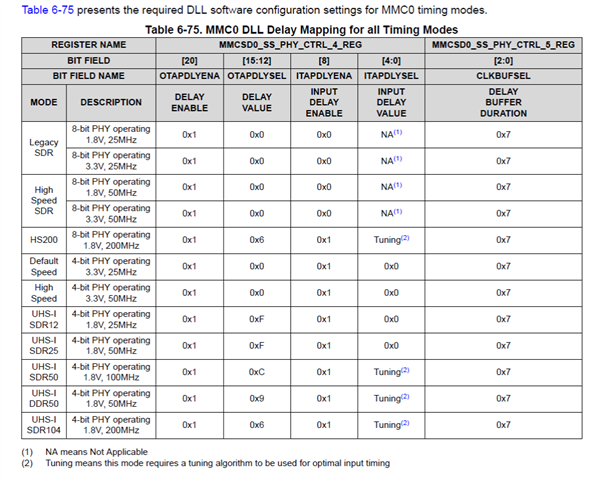
I have asked for clarity as to his goals.  I am assuming it is the fastest speeds possible.  Would that be the HS200 8bit at 200 MHz rather than the 3.3v @ 50MHz he notes above?

Best Regards, 

Blake

  • Hello,

    HS200 is the highest speed mode supported by the MMC0 for the eMMC cards.

  • I see there was more to the question that I had missed:

    I have a few questions about the MMC0 interface, which is what we will be using for our eMMC NAND flash. Our plan is to run it at 52MHz, DDR. 

    1. I noticed that there don’t seem to be any bits to change the drive strength of the MMC pins. They all seem to be reserved:

    2. Also, the EVB schematic has a few notes about the eMMC0 interface and its internal pulls. 

    • Has TI done enough testing to confirm that external pull-ups are not needed?
    • What about R491 (50K pull-up on the clock signal)? Does TI have test results to show that it is needed or not needed?
    • What about R499 (10K pull-down on the clock signal)? Is that needed?

  • 52MHz is not mentioned anywhere in the table you inserted. We only support up to 50MHz for the modes defined to operate at 52MHz in the eMMC standard due to the AM62Lx PLL operating frequencies and internal clock dividers. The eMMC standard doesn't allow 3.3V signaling for any mode that operates over 52MHz. So, HS200 is limited to 1.8V operation.

    The table you inserted will be updated in the next revision of the datasheet. We will be adding a new row for "High Speed DDR" that includes operation at 1.8V or 3.3V, but the frequency will be limited to 40MHz in this mode. We are also removing the last three rows in the table. This is being done because the AM62Lx MMC0 port only supports eMMC and embedded SDIO. It does not support SD Cards and embedded SDIO devices only operate up to UHS-I SDR25.

    The SDIO buffer type implemented on MMC0 signal functions have a fixed 40-ohm source impedance.

    The schematic snapshot you inserted does not appear to be correct for AM62Lx. The recommended external pulls for the AM62Lx MMC0 signals when connected to an eMMC device is a pull-down on CLK, a pull-up on CMD, and a pull-up on DAT0. I recommend using standard tolerance 47k-ohm resistors. These pulls are required to hold a valid logic state on the unprotected eMMC inputs until software initializes the MMCSD0 host controller and the associated IOs since the AM62Lx IOs associated with these signals are turned off by default. The eMMC standard requires all eMMC device to provide internal protection on its DAT[7:1] inputs by turning on internal pull-up resistors by default. The eMMC device will turn off its internal pull-ups on DAT[7:1] when entering 8-bit mode or will turn off its internal pull-ups on DAT[3:1] when entering 4-bit mode. The host is expected to turn on its internal pull-ups on these signals when the eMMC devices turns off its internal pull-ups on these signals. Therefore, external pull-up resistors should not be required for DAT[7:1]. However, we recently found the TI software was not turning on the host pull-ups on these signals, which means these signals were floating when not driven. I assume this will be fixed in a new revision of the software.

    Regards,
    Paul

  • Hi Paul, 

    I have notified my customer and they are evaluating the reply.  Hopefully I will be able to close the thread tomorrow, but will leave it open for today in case the engineer has any followups.

    Thanks for the quick and thorough response!

    Best Regards, 

    Blake

  • Hello Blake, 

    Adding additional information for you to review

    SK design files:

    There were some discrepancies observed in the previous revision.

    All the required updates were made and released recently.

    TMDS62LEVM Design File Package (Rev. B)

    SPRCAL6B.ZIP (97010 KB)

     Refer below link for quick reference to schematics:

    (+) [FAQ] AM62L ( AM62L32 , AM62L31 ) Custom board hardware design - Design notes and Review notes for Reuse of EVM TMDS62LEVM Schematics - Processors forum - Processors - TI E2E support forums

    We have the standard PDF and smart PDF with component details embedded.

    The EVMs have been tested with the schematic configuration.

     Regarding the schematics picture provided above:

    The schematics posted in the E2E seems to be customer schematics.

    Seems like customer reused the schematics of the SK and did not reconfigure the DNIs.

    We have this note in the Hardware design considerations document:

    When the SK design (schematic) is reused, the DNI settings for all the components can reset. Make sure the DNIs are reconfigured (populating DNIs can affect the functionality).  

    https://www.ti.com/lit/pdf/sprujc9

    Regards,

    Sreenivasa

  • Great info Sreenivasa!  Thanks for looking out for the customer.  This will save huge problems when the first schematic comes in for review.

  • Hello Blake, 

    Thank you for the note.

    In case the schematics review needs to be prioritized, please give an heads-up on the likely date when the request will be submitted.

    Regards,

    Sreenivasa

  • Hello Blake

    Quick note:

    In case customer is reusing the AM62L EVM schematics, there are a few DNI components in the clock, reset, OSPI, SD card, Ethernet USB and other sections.

    The recommendation is for the customer to verify the DNIs in the BOM or the SK EVM PDF schematics and make the required updates to DNI.

    Regards,

    Sreenivasa

  • Hi Paul,  

    We are at a competitive disadvantage as they are space constrained and tied to 3.3v.  80 vs 104 MBPS.  Do you see any options?

    Here is my discussion with the Customer:

    So you are looking at SDR 50MHz 8-bit at 3.3V correct? [Customer] Correct, but with the current information, I would rather do the currently supported 40MHz DDR, 8-bit, 3.3V (per Paul’s earlier answer) since that would give me higher throughput.

    So if you could do DDR 50MHz or SDR 100MHz at 8-bit/3.3V that would double your speed and avoid level shifters correct? [Note: These aren’t currently published options – but I wanted to chase down Why and IF they could be made effective options – but I wanted to sanity check they would solve your problem first].  [Customer] Yes, SDR at 100MHz 8-bit/3.3V would, theoretically, solve my problem. Practically, it won’t solve my problem since that is not part of the eMMC specification and therefore you won’t find an eMMC device that would support this (SDR at 100MHz, 8-bit, 3.3V).

    Also – it would appear that 200MHz would ~double your current throughput at the expense of space you don’t have IF you dropped to 1.8V with a Level shifter. Correct? [You have taken this option off the table with a prior email – but I want to make sure I am understanding correctly]. [Customer] Correct.

    What about 40 MHz 3.3V DDR that is noted below?:

    The table you inserted will be updated in the next revision of the datasheet. We will be adding a new row for "High Speed DDR" that includes operation at 1.8V or 3.3V, but the frequency will be limited to 40MHz in this mode. We are also removing the last three rows in the table. This is being done because the AM62Lx MMC0 port only supports eMMC and embedded SDIO. It does not support SD Cards and embedded SDIO devices only operate up to UHS-I SDR25.

    That would give you an effective 80 rather than 104 but much better than 50. Is this an option you are considering? [Customer] Yes, this is the option I am planning on using as it is the best practical option for our current situation.

    Ideas or is he using our best option?

    Thanks,

    Blake

  • Yes, High Speed DDR mode operating at 40MHz is the highest throughput option if they are not willing to use 1.8V signaling.

    From my understanding, it is possible to operate the MMC0 peripheral in High Speed DDR mode at 50MHz, but there is a throughput limitation in the internal data path that causes the effective bandwidth of the peripheral to be better when operating at 40MHz vs 50MHz. Therefore, you should not simply judge data throughput based on peripheral operating speed. 

    Regards,
    Paul

  • Hi Paul, 

    The customer asks:

    Can TI confirm that this software issue has been fixed? If it has been fixed, then I will remove the 47K pull-ups from MMC0 data lines (D1..D7):

    [Paul writes] Therefore, external pull-up resistors should not be required for DAT[7:1]. However, we recently found the TI software was not turning on the host pull-ups on these signals, which means these signals were floating when not driven. I assume this will be fixed in a new revision of the software.

    If it has not been fixed, when does TI anticipate this will be done? Itron will be using drivers (bare metal and Linux) from TI so I’m assuming if it’s not fixed in your drivers, then it won’t be fixed in whatever we are using.

    Advice for what the customer should do in his schematic for bare metal / Linux?  Thanks!

    Best Regards, 

    Blake

  • So for everyone who finds this thread - software weak pulls will be enabled for the AM62L eMMC use starting in the 11.02 SDK release. 

    Best Regards, 

    Blake