Other Parts Discussed in Thread: J722SXH01EVM, BEAGLEY-AI
Tool/software:
hi,
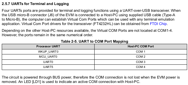
on the evaluation board J722SXH01EVM, I see the below UART ports of J722S are connected to FTDI FT4232HL (beside RTSN/CTSN for each):
A) F19/F20 (UART0_TXD/RXD)
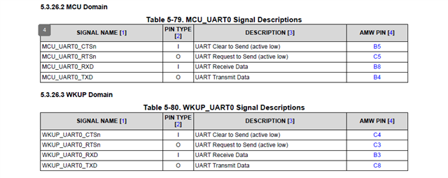
B) C8/B3 (WKUP_UART0_TXD/RXD)
C) B4/B8 (MCU_UART0_TXD/RXD)
D) H27/J27 (SOC_UART5_TXD/RXD)
Could you suggest which are needed for designing a new board and do software development on it.
(UART to USB bridge like the FTDI chip won't be present on the board to be designed, and we might want to debug R5 tispl.bin-uboot as well).
The usecases inlude both "boot from UART and flash firmware" and "MCU R5F application runtime debug UART prints".
1. A) + B)
2. A) + B) + C)
3. A) only (re-route output to this by firmware change)
4. all of A) B) C) D) (I don't think D is quite needed though)
Less number of pins preferred if possible.
If we went for option 3. would it complicate development of boot code (R5 side uboot) or MCU R5F application uart debug?
please suggest.
BeagleY-AI's layout (uart) puts F19/F20 to one of JST 3pin header, and one linux console gets assigned to its USB-C port,
Other (application use) UARTs going to the 40-pin expansion header, as it seems. Was R5 tispl.bin console printout routed to F19/F20 on BeagleY-AI?
Thanks in advance!
pages that I'm looking at:
* 3.1.1.9.1. Booting U-Boot from the console UART