A related question is a question created from another question. When the related question is created, it will be automatically linked to the original question.
Do you mean you want customer to provide the waveform when there are some packets transmitting in the Tx side? However, from the register dump in Tx customer discussed with Takuma, there is indeed some parts of Tx are transmitted while some parts are not.
Do you want to make it sure for this TX waveform it should be taken when some Tx parts are transmitting matching to the Tx register dump result?
Mark and I talked just now. There were some waveforms previously submitted by customer. We would like to see the same waveforms, but before the isolation circuitry.
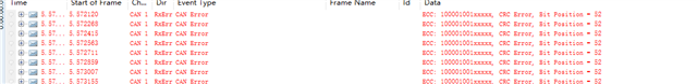
I ensure that the baud rate and sampling points of TDA4vH and CANOE remain consistent during the testing process.According to your and Mark's suggestions, I compared the TX and CAN signals before isolation, as shown in the figure below.Please help analyze.
This is the signal measured under normal conditions:
This is the signal measured under abnormal conditions:
Thank you for the waveforms. In the abnormal case, the TXD line is stuck dominant during the acknowledge bit.
Based on my research, this could be due to hardware or software issues.
From TJA1463 datasheet,
From TCAN1463 datasheet (TI equivalent),
Notably, "TXD fault stuck dominant: example PCB failure or bad software".
Is it possible that reflowing the board corrected any board errors and allowed the pre-production part to work on the new board? I suggest this because the software is identical in abnormal and working case; and to reiterate, pre-production part and production part share the same SR so the SoC is not expected to behave any differently.
I am the hardware engineer in charge of this project. I have read your reply and need to clarify some hardware issues:
1. When the XJ784S4 was soldered with this hardware status, the CAN communication was normal. (The TDA4VH and XJ784S4 are boards from the same batch, with only the SOC difference in the EBOM.)
2. When using this hardware status board, the CAN loopback communication between TDA4VHs had no errors on the CAN bus.
3. Since the TJA1463 and TCAN1043 are pin-to-pin compatible, we have tried to replace them, but the communication is still abnormal.
4. The CAN circuit routing and layout were considered during the layout stage, and this solution has worked without issues in our other projects.
5. We have verified through X-RAY that there are no problems such as cold soldering or missed soldering on the SOC.
6.The reception of the CAN bus is also abnormal at present. We can measure that the RX signal enters the SOC, but no data can be received in the SOC.
I secured a production part (TDA4VH88TGAALYRQ1) and performed a simple CAN communication test between two of our EVMs using MCAN3 (TCAN1043 part). Identical software on both boards: SDK 11_00_00_08 with J784S4 device tree modified to enable MCAN3.
EVM#1 populated with TDA4VH88TGAALYRQ1 acting as transmitter node
EVM#2 populated with XJ784S4GAALY acting as receiver node
As expected, CAN communication at 500kbps is successful.
The waveform reveals MCAN3_TX signal is not stuck low (dominant) during the acknowledge bit.
Have you tested board-to-board communication yet?
Additionally, can you please provide all device tree details for configuring the transceiver? I'm primarily curious about pinmux/padconfig.
Thank you for your reply.Based on your description, you used the EVM boards 'TDA4VH88TGAALYRQ1' and 'J784S4' for cross-testing, and they work properly. We have tried cross-testing with various devices, including CANOE, ZCANPRO, and other development boards. We also conducted board-to-board tests, using the 'J784S4' EVM board and our 'TDA4VH88TGAALYRQ1' development board for cross-testing, and the result was consistent with the previously described issue: they cannot communicate properly. I will upload my device tree configuration:
We also conducted board-to-board tests, using the 'J784S4' EVM board and our 'TDA4VH88TGAALYRQ1' development board for cross-testing, and the result was consistent with the previously described issue: they cannot communicate properly.
Can you also share with us the software configuration by using "ip -details link show <mcan_x>" on both J784S4 and TDA4VH side in above test case? Similar to screenshot in this E2E thread: RE: TDA4VH-Q1: Enable BRS support in CAN-FD