A related question is a question created from another question. When the related question is created, it will be automatically linked to the original question.
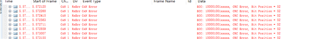
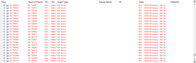
Hi, In standard CAN mode and CANFD mode, communication can only be done when the arbitration segment is 1 Mbps, and setting other values, such as 500kbps, will cause communication failure. The following is the error message prompted by CANOE。Pleasehelpmeanalyzewhatmightbecausingthis,Thank you!
Hello,thedriverofMCANIamcurrentlyusing,theSDKversionisti-processor-sdk-linux-adas-j784s4-evm-11_00_00_08,asforswitchingthebaudrate,Iset the baudratethroughtheiplinksetmain_mcan4typecanbitrate500000command
Hi, Takuma, Iconfirm that the "bitrate","dbitrate"and"sample-point"and"dsample-point"configurationsbetweenTDA4VHandCANOEareconsistent,andcurrentlyat1MbpsIcansendtoCANOEthroughTDA4VH,andCANOEcanalsoreceivenormally,butontheotherhand,sendtoTDA4VHthroughCANOE,TDA4VHcannotreceiveCANframes
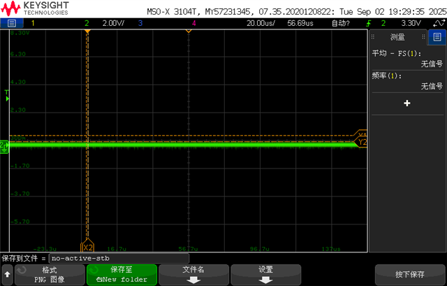
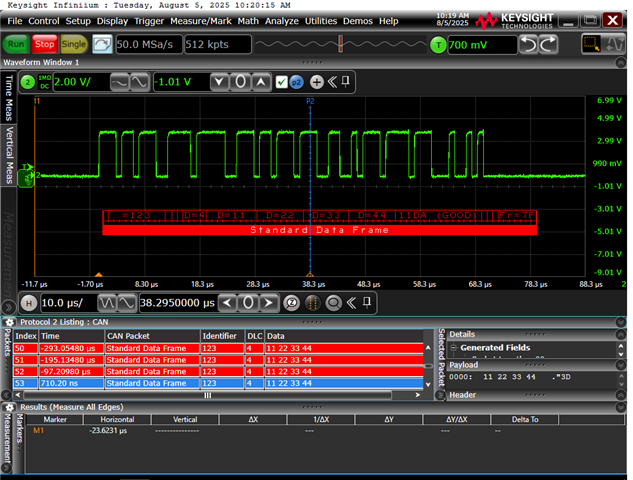
I'msurecandumpisrunning. Ialso tried to grab the waveform with an oscilloscope,and found alittle abnormality,Iwill attach two pictures,we use two CAN (mcu_mcan0,mcu_mcan1)on the TDA4VH for spontaneous self-reception,whether it is CAN or CANFD mode,it can communicate normally,but once connected to CANOE for comparison,an error will occur,resulting in bus-off,we make sure that the baud rate and other configurations of CAN on TDA4VH are consistent with CANOE.Theterminalresistorsalsohavenormalconnections.IfoundthatattheendoftheCANframe, the waveformwasabitabnormal.
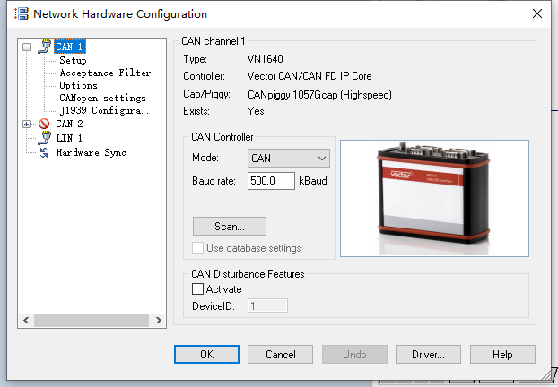
Judgingfromthecurrentsituation,afterconnectingtoCANOE,itcannotcommunicatenormally. IusedtheipcommandtocheckthestatusoftheCANcontroller,andalsochecked the configurationinformationofCANOE,which I attached. Afteranabnormalcommunication,usetheipcommandtoviewthestatusofthecontroller,thestatusis"ERROR-PASSIVE"and"BUS-OFF".
Can you also show the sample-point, clock, qlen of the CANOE so that we can do a comparison? If those settings do not exist in the CANOE tool, can you search for documentation that has this information?
Idon'tthinkthesettingofthesamplepointhasmuchtodowithwhether the standardCANmodecancommunicate,ofcourse,Iwillset the samplepointtobeconsistentwhenItest.
Hi Takuma, Because we have used TDA4VH samples before, there is no problem with it, but after replacing it with a mass-produced chip this time, the CAN communication is abnormal. In the previous test process, we did not specifically set the sample point in CAN mode, and we have always used the default sample point configuration, and there is no problem in the test. After replacing the mass-produced chip this time, we specially went to the same sampling point for testing, but it still didn't work.
What is the specific part number for "TDA4VH samples" and what is the specific part number for "mass-produced chip"?
How many boards are having the CAN issue? And how many total boards are there?
Are there any difference in software? For example, is the same SDK version used for sample and mass-produced chip boards?
Basically, I would like to understand if this is a systematic issue where all boards are having the CAN issue, or if it is a rare failure. And I would like to understand if there is any difference in software.
2.Currently,allboardsthatuseproductionchipshaveproblemswithCANcommunication,and there arealsoproblems with SERDES.
3.Therearenochangesinthesoftware,wearestillusingthesameversionoftheSDKas the sample"XJ784S4GAALY",andthesefunctionshavebeensuccessfullydebuggedonthesample, butthereisaproblemwiththenewmassproductionchip"TDA4VH88TGAALYRQ1", and wealsodoubtwhethertheSDK has been updated,andafterdebugging with the latest versionoftheSDK,theproblemstillexists.
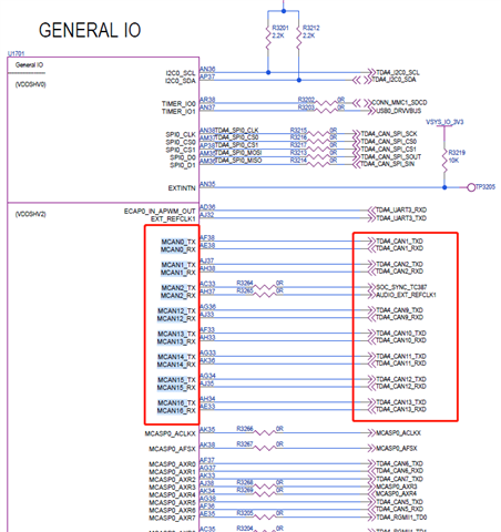
Wealsouse the mass-producedchip"TDA4VH88TGAALYRQ1" because the twochipsarecompatiblewitheachother,andtheschematic is almostunchanged compared to the"XJ784S4GAALY"chip,andthepreviousschematicdesignisdirectlyreused.
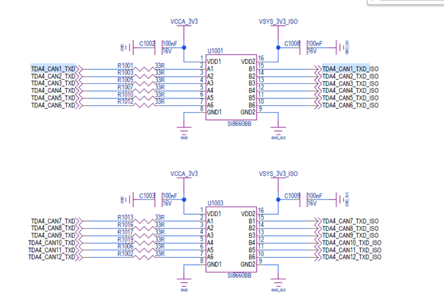
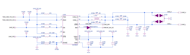
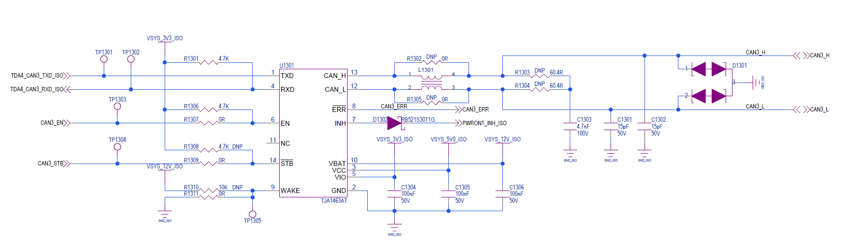
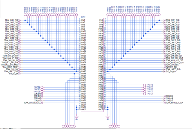
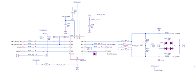
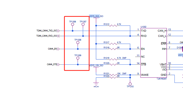
Can you also share the XJ784S4GAALY version of below schematics?
I am not knowledgeable with the connection for this particular CAN transceiver, but I would like to understand if there are any difference with the RXD, EN, STB, and WAKE pins. I see the RXD pin has a pull-up resistor which typically is not necessary, and WAKE is pulled down.
Iwillattachtheschematicdesignofthechip"XJ784S4GAALY",asyousaid, compared tothepreviousprinciple, it doesaddapull-upresistorto the RXpinoftheCANtransceiver.Couldthisbethecauseofthecommunicationfailure?
As an experiment, could the pull-up resistor be removed?
I am not aware of a requirement to pull up the RX line for CAN, so I am not sure what the effect is for including the resistor or removing the resistor. However, since the issue is happening only on the RX, and a difference between working and non-working system is the pull-up resistor on the RX line, removing the pull-up would be a good experiment.
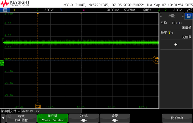
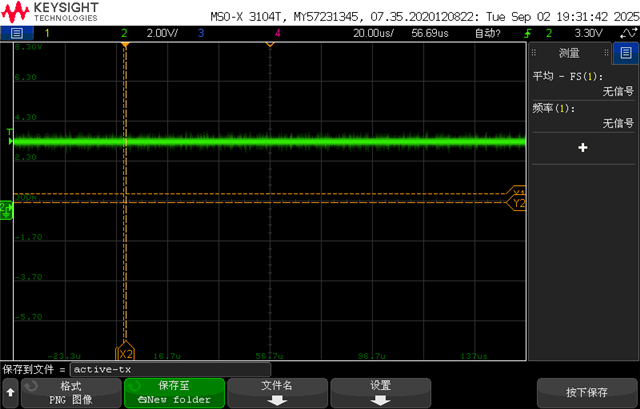
Icantry to seeifIcanremovethepull-upresistoron the RXandtestit. However,not only RX is aproblem,but also TX,as Idescribed before and attached pictures,Iuse TDA4VH as the transmitter and CANOE as the receiver,CANOE cannot receive data correctly,only when TDA4VH and CANOE are configured in CANFD mode,and the baud rate is set to 1Mbps,the communication is normal.InstandardCANmode,thereareproblemswithbothTXandRX,youcanlookthroughtheimagesIprovidedearlier, this should help us identify the problem as soon as possible.
I took a look at the schematics a bit more and noticed that the CAN transceiver used in old working and new non-working system are different. So, I do not think this is an issue with sample vs mass-produced chips. Instead, I think it is more reasonable to suspect the issue is due to the hardware changes done on the new board related to the CAN transceiver.
So please, continue with the RX pull-up resistor change. I also noticed that the VBAT related connection is slightly different, and there is slight difference with the termination due to SPLIT termination.
Wetriedremovingthepull-upresistorontheRXfortesting,anditwasstillthesame as before.Forthechangeyousaidaboutthesplitterminal,ourCANtransceiverhaschangedfromTJA1043 to TJA1063,itseemsthatTJA1063doesnotneedasplitterminal,andwealsotriedtochangetheTJA1063to the originalTJA1043transceiverfortesting,butitstillcan'tcommunicate.
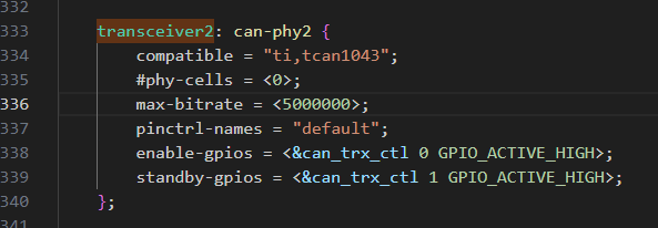
The change with standby and enable gpios is significant. What is the reason for commenting out standby gpio for working TJA1043 case?
As shown below, not defining standby-gpios should cause an error in the transceiver driver, so I assume there were changes done to the Linux kernel driver. There may be some changes in the kernel driver which might be conflicting with TJA1063 since ti,tcan1043 and ti,tcan1042 both use the same kernel driver.
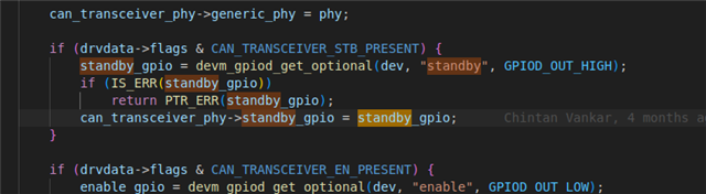
You are right, the standby/enable is using the optional API, so error should not necessarily be triggered. Hardware-wise, the old and new board looks to have standby floating and not pulled up or down, so it is a bit strange though.
Other than the CANOE device, are there any other devices you can test the TDA4VH CAN interface?
Duringtesting,Icontrolledthestandbyandenablepinstatesof the transceiverviaGPIOandmeasuredthemwith a multimetertoensurethat the pinstatewasproperlycontrolled. As Isaid before,the TDA4VH can communicate with tools such as CANOE at certain baud rate settings,so Ithink the transceiver should be in anormal working state.InadditiontoCANOE,wealsotesteditwithZCANPRO, and theresultswerethesame as before.
Does a pre-production part work on the new board? And vice-versa- does a production part work on the old board? I would like to confirm the behavior of pre-production vs production part on the new and old boards.
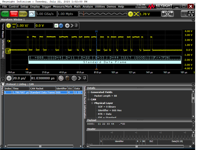
Could you please capture CAN waveforms from a passing case and a failing case? Please include the TX, RX, and EN signals coming from the SoC for both cases.
Afterreplacingtheoldchip"XJ784S4GAALY",wetriedagainandfoundthatmostoftheproblemsweencounteredbeforehadbeensolved,butthecurrentuseofmass-producedchips"TDA4VH88TGAALYRQ1"isstillnotgood,andthesituationisthesameasbefore.For the waveform of the CAN signal, I have uploaded the normal and abnormal waveforms of the TX signal before.
If I understand correctly, you retested the pre-production part on the new board and it is now working despite previously not working. Can you please fill out the following table for us to understand conditions and results?
Old Board
New Board
XJ784S4GAALY
Pass? / Fail?
Pass? / Fail?
TDA4VH88TGAALYRQ1
Pass? / Fail?
Pass? / Fail?
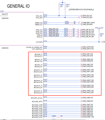
Can you please confirm if you're seeing this issue on all CAN instances?
Also, please provide TX, RX, and EN waveforms at the SoC in a working and a non-working case (eg. TP6501, TP6502, and whichever test point at the SoC for CAN1_EN in your new schematic), so we can know the SoC CAN bus behavior in both cases.
Please help analysis based on customer's waveforms. Customer told me that they have 4 non-working boards all using the TDA4VH88TGAALYRQ1, they switch one of these boards to XJ784S4GAALY, just change TDA4VH88TGAALYRQ1 to XJ784S4GAALY on this board, keeping the rest parts the same, the problem seems disappeared, and the results customers provided in the above reply shows abnormal (other boards using TDA4VH88TGAALYRQ1) & this new board after switching to XJ784S4GAALY.
I do suspect there is some HW related designs need to be optimized from the experiment result, any clue you could share please?
Can you please confirm where in the schematic you're probing when capturing the TXD signal in the working and failing case?
Can you probe at various points in the TXD signal path and share the results (eg. TP6505 at SoC, TP1301 after the digital isolator and before the CAN transceiver)? We would like to know how this signal looks at various points before and after the digital isolator in its path.
Same as above for RXD signal.
Why is there a pull-up resistor on the RXD line between the digital isolator and CAN transceiver?
Does the TDA4 SoC report any MCAN errors in the failing case?
Please refer to MCAN Protocol Status Register section in MCAN Debug Guide
Both pre-production part and production part are the same silicon revision so there are no differences expected with the MCAN.
EDIT: Few more items to check if you could please.
Are there any electrical shorts between TXD and RXD signals?
1.These signals are measured at the test point between the isolator and the transceiver, as shown in the figure below.
2. The pull-up resistor on the RX is reserved by us. We also tried removing this pull-up resistor for testing, but there was no change. Will this pull-up resistor have any impact on communication?
3. I will supplement the status of these registers later.
The answers to the several questions you supplemented are as follows.
1. There is no short circuit phenomenon between RX and TX.
I have pushed customer to provide the TXD signal waveforms as soon as possible. And before you receive that, here is a full log dump with very detailed comparison between the TDA4VH88TGAALYRQ1 & XJ784S4GAALY. We indeed could see some register dump difference and hope this could provide more clue for you to figure out the problem.
Could you please have a look of this excel sheet please? Customer spent a lot of time to get this. (it includes idle state, Rx, Tx, separately)
Are there any other CAN devices you can try to test the TDA4VH with? So far, it sounds like we have verified that TDA4VH can communicate at different speeds with itself, and CANOE can communicate with ZCANPRO. Is it possible to test TDA4VH and ZCANPRO combination? Or, if I interpreted your information wrongly and you have already tested TDA4VH + ZCANPRO, is it possible to test with CANOE + ZCANPRO, and test that different arbitration and data speeds can be set?
As for the register dump and reason why it would be good to test with other devices, the register dump seems to point to issues during initialization.
For RX:
A "Protocol Error in Arbitration Phase" interrupt is being set for failed case. As mentioned at start of the thread, I have seen this when there is a mismatch between receiver and transmitter for sample-point, the lower speed arbitration bitrate, and/or data bitrate.
Additionally, nothing looks to be in RX FIFO for failed case based on RXF0S and RXF0A, also pointing to failure during arbitration.
For TX:
Based on CCCR bit 1 being set, also looks to be some issues in init/sync. TXBTO and TXBRP is also interesting for TX since each bit represents some transmission had occurred or not, and in "Fail" system it looks like some transmissions occurred, but not all.
According to Mark's suggestion, we measured the TX and RX before isolation, and the results are as follows.
TX:
RX:
Currently, we have tested the several forms you mentioned. The TDA4VH itself can communicate through its two CAN channels, but it cannot communicate properly with CANOE or ZCANPRO. However, CANOE and ZCANPRO can communicate normally with each other, and we have also changed the transmission rate and sampling point for testing, and both sides can communicate normally.
For RX:
During the testing process, we first ensure that the parameters on both sides remain consistent, but the RX still cannot receive any data.
For TX:
You are correct in your understanding; during the transmission process, some parts were transmitted while others were not, resulting in the bus entering a bus-off state.
Thanks for sharing the waveforms but I believe these are inconclusive without seeing the SoC transmit or receive any CAN packets. I would have expected to see something similar to probing in between the digital isolator and the transceiver.