Other Parts Discussed in Thread: SYSCONFIG,
Tool/software:
Hello TI support team.
The SDK is mcu_plus_sdk_am64x_08_06_00_45.
I would like to ask a question about CR5 interrupts and MCSPI_transfer.
An interrupt from the PRU is generated to CR5 at 20 kHz with PRU_ICSSG1_PR1_HOST_INTR_PEND_0.
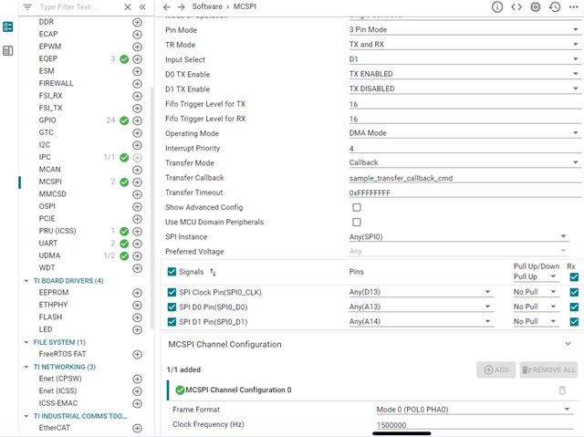
Additionally, in CR5, a 20-byte SPI transfer is performed using the MCSPI_transfer function with a timer interrupt (1 kHz).
In this case, the interrupt priority of the 20 kHz handler is 1, and the 1 kHz interrupt priority is 5.
If there is only a 20 kHz interrupt, the 20 kHz interrupt handler will be called periodically.
However, if an SPI transfer of a 1 kHz timer interrupt is performed, the timing of the 20 kHz interrupt occurrence will be shifted. See the diagram below.

This is probably because interrupts are disabled with MCSPI_tranfer.
I would like to call the 20kHz interrupt handler periodically without disabling interrupts during SPI transmission.
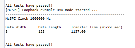
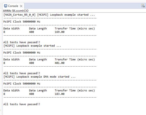
Furthermore, the processing time of MCSPI_tranfer is long.
As can be seen from the above figure, it takes nearly 30us.
Please tell me how to solve this.
Best regards,
Kiyomasa Imaizumi.