This thread has been locked.

If you have a related question, please click the "Ask a related question" button in the top right corner. The newly created question will be automatically linked to this question.

AM3358: OSD3358 SPI1 CS0 Won’t Assert Low When Communicating with SPI Slave

Part Number: AM3358


Tool/software:

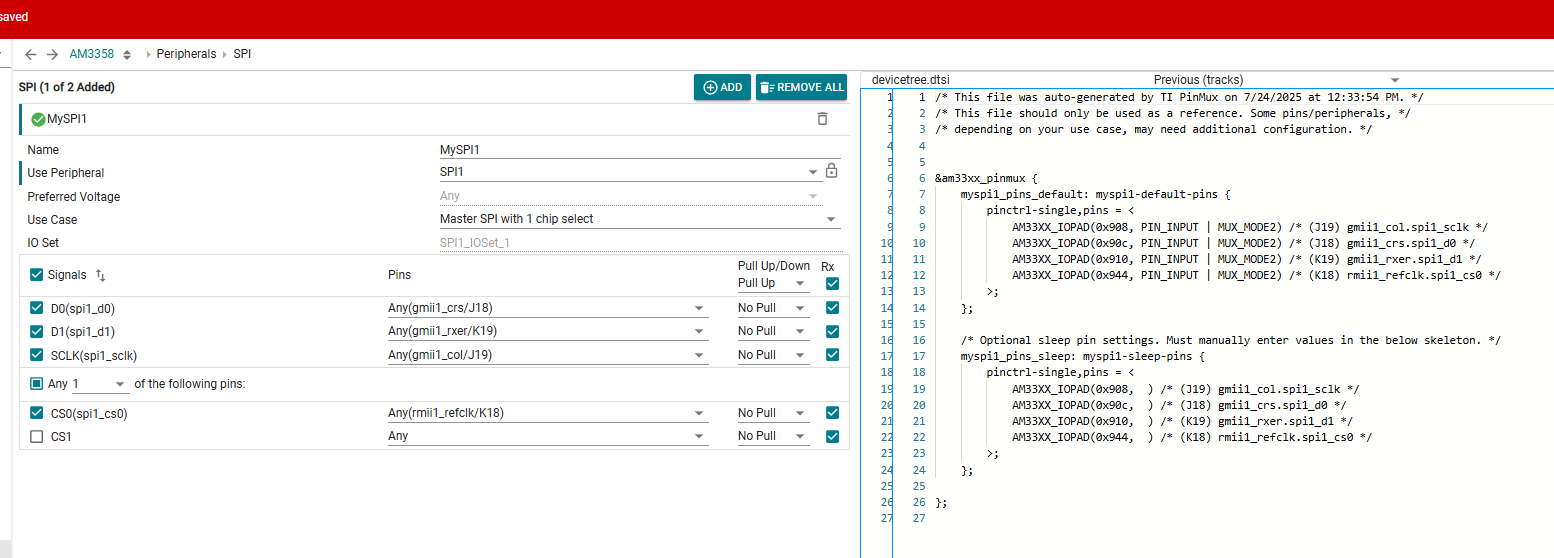
Has anyone seen SPI1 CS0 stay high on an OSD3358 when the bus is routed over the MCASP0 pins (MODE 3)? My SCLK only appeared after I set its pad to PIN_INPUT_PULLUP | RXACTIVE—a quirk that fixed the clock—but CS0 never goes low during transfers to a SPI slave module, so all reads return 0xFF. I’m using the usual DT pins (SCLK/MISO as input‑pullup, MOSI/CS0 as output‑pullup) and haven’t yet tried unusual methods like making CS0 an input. Before I start flipping properties at random, is there a known pad‑mux or device‑tree tweak to get the McSPI master to assert CS low in this setup, or a minimal example that proves it works?

  • Hi Satya, I am sending this thread to our expert. Please allow him some time to come back to you

    Paula

  • Yes sure, Thanks Paula!

  • Hi,

    The AM335 setting shows as follows:

    We can modify the same and match it with the below configuration in dts file:

    Although the second screenshot is for AM62x, but the configuration of input/output can be followed for AM335 as well.

    NOTE: The AM62x setting is as following: D0 is MOSI and D1 is MISO, CLK and CS are self explanatory, please try to give the same input/output directions to the AM335 settings as well and this should make sure all lines are functioning properly atleast from configuration point of view.

    Let me know if this helps.

    Thanks,

    Vaibhav

  • Hi Vaibhav,

    Thanks for the follow-up! Before your reply, I had already configured the following pinmux for SPI1 routed over the MCASP0 pins, all in MODE 3:

    spi1_pins_default: spi1-default-pins {
    pinctrl-single,pins = <
    AM33XX_IOPAD(0x990, PIN_INPUT_PULLUP | MUX_MODE3) /* mcasp0_aclkx -> spi1_sclk */
    AM33XX_IOPAD(0x994, PIN_INPUT_PULLUP | MUX_MODE3) /* mcasp0_fsx -> spi1_d0 (MISO) */
    AM33XX_IOPAD(0x998, PIN_OUTPUT_PULLUP | MUX_MODE3) /* mcasp0_axr0 -> spi1_d1 (MOSI) */
    AM33XX_IOPAD(0x99C, PIN_OUTPUT_PULLUP | MUX_MODE3) /* mcasp0_ahclkr -> spi1_cs0 */
    >;
    };

    These settings were based on the TRM and AM335x pinmux reference, and match exactly with what you suggested from the AM6/AM62x PinMux tool, i.e. the directionality for each pin. I also verified that SCLK began toggling only after I applied PIN_INPUT_PULLUP | RXACTIVE to its pad, which seems to be a known quirk to get clock activity started.

    Given that, I expected CS0 to also behave correctly with PIN_OUTPUT_PULLUP, but it stays high even during SPI transfers (reads always return 0xFF). I haven't tried using spi-cs-high, cs-gpios, or configuring CS0 as an input because I don't have any GPIO pin controlling the CS0 and my slave device expects active_low on CS. I wanted to first confirm whether additional pad or DT tweaks are needed for CS0 like they were for SCLK. The below is what I see on my dmesg kernel logs. I tried to print the MISO, MOSI data as you can see below. I also tried probing the CS line on oscilloscope and I see it constantly high and not toggling to low when I load the slave device driver module.

    [ 3102.454720] nrc80211 spi1.0: Fail to c_spi_read_regs
    [ 3102.454729] nrc80211 spi1.0: Target not ready...
    [ 3102.757214] NRC tx: 50 80 00 10 4b f1 4a c5
    [ 3102.757243] NRC rx: ff ff ff ff ff ff ff ff
    [ 3102.757259] nrc80211 spi1.0: [_c_spi_read_regs] try to read register but SPI ACK is invalid

    Would you consider this configuration complete from a pinmux point of view? Or is there a subtle pad behavior or kernel quirk that might require cs-gpios or an input-mode setting to actually get CS0 to assert low?

    Thanks again for the help — looking forward to getting this working!

  • Hi,

    Thank you for the precise response.

    I am assuming you are going for the following pin? out of many listed in the datasheet of AM335?

    Regards,

    Vaibhav

  • Yes, that's the pin I am using.

  • In my .dts file I have set spi-max-frequency = <20000000>; (20 MHz)

    And, this is what my kernel dmesg logs show

    [ 3034.651009] nrc80211 spi1.0: setup: speed 16000000, sample leading edge, clk normal
    [ 3034.651068] nrc80211 spi1.0: setup mode 0, 8 bits/w, 20000000 Hz max --> 0


    Thanks for sharing the threads with me. I've gone through them and I see that they talk about the SCLK and how to set it as an INPUT to enable RXACTIVE. I've done that already and see the CLK pulse at 16 MHz just as my kernel logs indicate. I've attached a picture of that. The yellow channel is the SCLK and the pink channel is the CS0. Even when there is clock pulse, CS0 won't toggle at all as we can see here. Also, I've seen the spi_omap_mcspi.c driver code and I observed that theere is a macro (#define OMAP2_MCSPI_CHCONF0 0x2c). Doesn't this mean that the SPIEN is held high during the active state coz the bit 6 (EPOL) is 0 from the 0x2c value?


    Any suggestions on how to debug/analyze this issue would be of great help.


  • Hi,

    Thanks for the detailed inputs from your end with the waveform.

    Let me review them and get back to you in few business days.

    Thanks,

    Vaibhav

  • Hi,

    I am involved in some high priority issue, so please expect delayed responses on this thread.

    Thanks for your patience.

    Regards,

    Vaibhav

  • Hi,

    active state coz the bit 6 (EPOL) is 0 from the 0x2c value?

    To confirm this, we can do a set of experiment.

    Please check if the code flow or control is going to the API: 

    static inline void mcspi_write_chconf0(const struct spi_device *spi, u32 val)

    If it is, then what is the val being written?

    Thanks,

    Vaibhav