Part Number: AM6442
Tool/software:
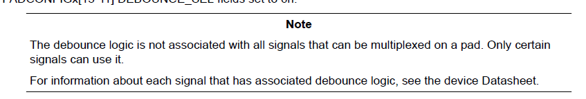
I am trying to set the debounce function for the AM6442 GPIO.
The target GPIOs are GPIO1_64 and GPIO1_65, and I tried to set the period to the "value closest to 1us".
I created the following initialization function and placed it immediately after Board_init() of the application running on the R5F0-1 core.
void DebounceInitialize(void){
CSL_mcu_ctrl_mmr_cfg0Regs *regs = (CSL_mcu_ctrl_mmr_cfg0Regs *)(uintptr_t)CSL_CTRL_MMR0_CFG0_BASE;
volatile uint32_t *debounce1Reg = NULL;
debounce1Reg = ®s->DBOUNCE_CFG1;
CSL_REG32_WR(debounce1Reg, 53);
uint32_t baseAddr;
volatile uint32_t *regAddr;
uint32_t setting;
baseAddr = CSL_PADCFG_CTRL0_CFG0_BASE + PADCFG_PMUX_OFFSET;
Pinmux_unlockMMR(PINMUX_DOMAIN_ID_MAIN);
regAddr = (volatile uint32_t *)(baseAddr + PIN_I2C0_SCL);
setting = (CSL_REG32_RD(regAddr) | PIN_DEBOUNCE1_ENABLE);
CSL_REG32_WR(regAddr, setting);
regAddr = (volatile uint32_t *)(baseAddr + PIN_I2C0_SDA);
setting = (CSL_REG32_RD(regAddr) | PIN_DEBOUNCE1_ENABLE);
CSL_REG32_WR(regAddr, setting);
Pinmux_lockMMR(PINMUX_DOMAIN_ID_MAIN);
return;
}
To verify that the settings were reflected, I performed the following tests.
- Set an interrupt to "display in debug output" on GPIO1_65.
- Run the application on the AM6442 and input a negative pulse with a width of 0.5us to GPIO1_65.
I predicted that "no interrupt would occur," but in fact an interrupt did occur.
I think there is an error in the initialization procedure and the settings are not as intended.
Please tell me the correct way to set it up.