AM69A: AM69A UART is not sending/receiving CCCCC

Part Number: AM69A
Other Parts Discussed in Thread: AM69, SK-AM69, TDA4VH

Tool/software:

HI TI:

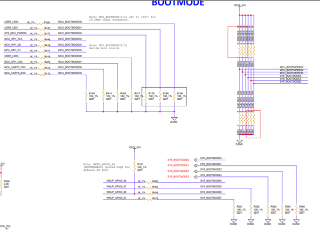
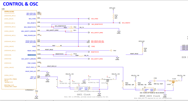
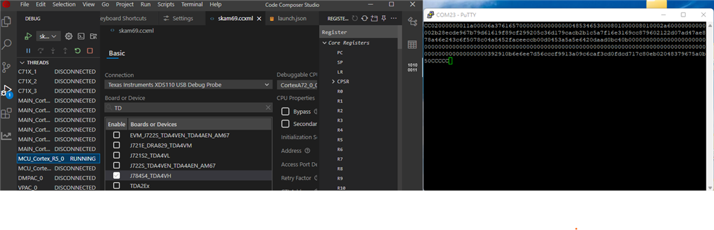
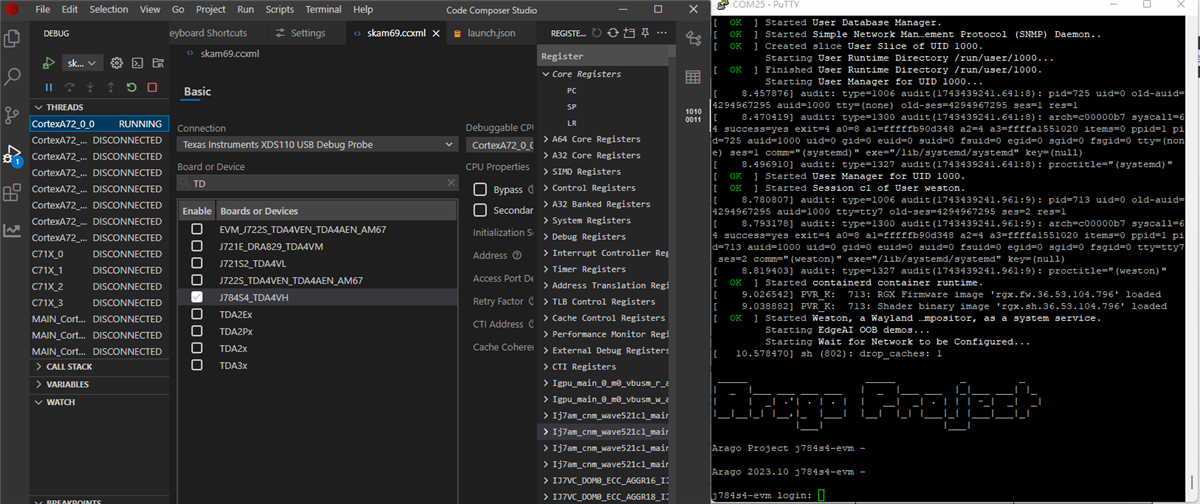
"I have a custom board using AM69A. According to the document top_cpld_j7ahp_sk, I configured the resistors for UART boot mode and used PuTTY to monitor the Communication Port at 115200 baud rate, but I don't see any CCCC characters. I have measured the PMIC timing and voltage levels using TPS6594133A IC, and everything looks normal. The CLOCK FREQUENCY is 19.2MHz. Can you help me with further debugging?"

  • HI Andew,

    Can you provide the hardware schematics of UART?

    Regards

    Gokul

  • HI Gokul :

    These are my hardware schematics of UART

    Thanks and Best Regards

  • Hi Andrew,

    Thanks for providing the schematic. Can you please specify which UART port you are attempting to use? 

    EDIT: And could you also provide schematic to the bootmode pins?

  • HI Mark 

    I am going to use U159 to connect  to SOC(AM69) .Here is the capture of circuit .Sorry i got a wrong picture before.

    And here is the schematic of the bootmode pins .I don't use CPLD but use register to config the   bootmode pins .According to the document "top_cpld_j7ahp_sk".I set MCU_BOOTMODE3,4,5 ->HIGH,and SYS_BOOTMODE0,4,6->LOW to enter the uart mode.

  • The BootROM does not use HW flow control – so TX/RX should be sufficient.

    MCU_UART0 and WKUP_UART0 might be available on several different pin locations.  But BootROM requires specific pin locations for booting:

    Pins J37, K38 for MCU_UART0, Pins K35, K34 for WKUP_UART0.  This appears correct on schematic.

    Have you verified the device is existing reset?  MCU_RESESTATz and RESETSTATz should both be '1' (high).

  • HI Robert

    According schematics ,I have got 3.3v on MCU_RESETZ and RESETSTATZ.

  • Andrew, did you mean you are measuring 3.3V when probing TP51 (MCU_RESETSTATZ) and TP101 (RESETSTATZ)?

    If yes, the device should have exited reset; can you try NO BOOT mode and check if you can connect to the device through CCS?

  • HI MARK 

    Thanks for your reply.Yes ,i have 3.3v when probing TP51 (MCU_RESETSTATZ) and TP101 (RESETSTATZ) on my custom board, But I don't have debug tool like  XDS110 JTAG Debug Probe right now ,i will buy one as soon as possible ,but i have one evb board  sk-am69 right now  . I want to figure out the behavior when i connect  to AM69  through CCS  .i am going to connect AM69 through on-board XDS110 of EVB SK-AM69.

    First ,I followed your instructions ,I config the  EVB SK-AM69 as no boot mode using SW2 and connect to CCS. Here have few qusetions

    1. I have not see AM69x or SK-AM69 on the device list  .so i choose J784S4_TDA4VH ,am i doing right? I have connected MCU_Cortex_R5_0 successfully

    2. When i pause MCU_Cortex_R5_0,there have many registers on the right side , which one shoud i check first if i can't see cccc in uart boot mode ? 

  • Hi Andrew,

    1. I have not see AM69x or SK-AM69 on the device list  .so i choose J784S4_TDA4VH ,am i doing right? I have connected MCU_Cortex_R5_0 successfully

    Yes, I believe this is fine.

    2. When i pause MCU_Cortex_R5_0,there have many registers on the right side , which one shoud i check first if i can't see cccc in uart boot mode ? 

    This NO BOOT exercise was mostly to confirm that we can communicate with the AM69A device. If we're able to connect through CCS, then we can try UART BOOT again. On the SK-AM69, can you try opening both ports in PuTTY and monitor if you see 'CCCC' characters on either terminal once the board is configured for UART BOOT and turned on?

  • HI Mark 

    Yes, I can see CCCC when I opened Putty in UART BOOT mdoe. I also can boot SK-AM69 with SD card in  SD card mdoe. 

    1.UART BOOT mdoe

    1.SD card mdoe

  • Thank you for verifying connectivity to the SK-AM69! My next steps would be to check booting on the custom board. I would also verify the custom board meets the requirements outlined by the schematic checklist: https://www.ti.com/lit/an/sprad91b/sprad91b.pdf