AM6421: Cacade timer setup to count 10uS ticks

Part Number: AM6421
Other Parts Discussed in Thread: AM62L,

Tool/software:

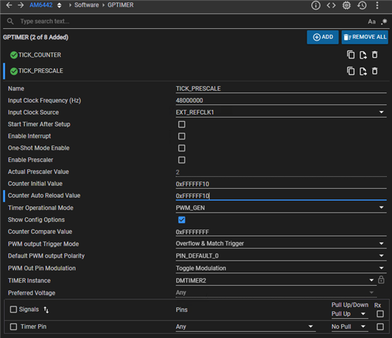
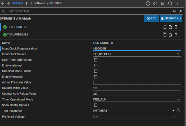
My design has multiple processors running from different clocks.  To synchronize critical timing, I am trying to use EXT_REFCLK1 to run two cascaded timers.  The prescale timer will provide a 10uS tick for the second free running timer.  I have chosen TIMER2 as the 10uS tick generator and TIMER3 to count 10uS ticks.  From the AM64x TRM, I found the CTRLMMR_TIMER3_CTRL CASCADE_EN bit in Section 5.1.1.5.65.  My question is regarding how to program this register.  I don't see any way to set this up from within the SysCfg system, and I can't find any example or an API that show how to handle this step during  startup and system initialization

  • Hi Bruce,

    Allow us sometime to get back to you.

    Thanks,

    Vaibhav

  • OK, For your information, this question is related to another question I asked, but I would prefer to operate this way with cascaded timers instead of my own ISR to count 10uS ticks.

  • Hi Bruce,

    I understand that your team is currently using AM64x, and there is another team is working on AM62L.

    Could you please confirm if these are two separate projects or part of the same project ?

    Timer Cascade Operation in MCU+ SDK :

    As of now, the MCU+ SDK does not support cascade mode in the APIs.

    However, if you want to enable hardware cascade operation manually, setting the CASCADE_EN bit in CTRLMMR_TIMER3_CTRL is a valid approach.

    This allows two consecutive timers (e.g., Timer2 and Timer3) to operate as a single 64-bit timer.

     Timer Cascade Mode  :
    • The timers are configured in cascade so that Timer2 (lower 32 bits) overflows and automatically increments Timer3 (upper 32 bits).
    • These two together act as a single 64-bit counter, ideal for long-duration timing.

     Limitation in Your Use Case:

    From what I understand, you’re trying to:
    • Use two timers fed with the same clock source
    • One timer to generate interrupts
    • The second timer to count a 10 µs interval independently

    This setup does not align with the cascade operation model, because:
    • In cascade mode, timers are tightly coupled — the second timer cannot be used independently.
    • You cannot independently configure one timer for interrupts and the other for a 10 µs interval when in cascade mode.

     Recommended Approach

    If you need:
    • One timer to generate a 10 µs periodic interrupt
    • Another timer to be a free-running timer for timestamping or duration tracking

    Then you should use two separate timers, each configured independently in non-cascade mode.

    Regards,

    Anil.

  • Anil,

    I can confirm that this is a separate project from the one using the AM62L.  My project uses both a AM6421 and a CC1354 that I need to keep synchronized to an external 48MHz TCXO.

    Your understanding is slightly incorrect.  I do want the two timers tightly coupled, with the first timer clocked by 48MHz connected to EXT_REFCLK1 on our board, and overflowing at a 10uS rate. The cascaded timer will count 10uS overflows, and the firmware will read the second timer to get synchronized elapsed time measured in 10uS ticks.  I was not thinking of using any interrupts in this setup. I got this concept by reading the AM6421 TRM, Section 12.5.3.1

    "When cascaded, TIMERi acts as a 32-bit prescaler to TIMERi+1, as well as MCU_TIMERn acts as a 32-bit
    prescaler to MCU_TIMERn+1. TIMERi / MCU_TIMERn must be configured to generate a PWM output edge at
    the desired rate to increment the TIMERi+1/ MCU_TIMERn+1 counter."

    I have 2 questions:

    1. Is this a valid approach?

    2. If so, how do I write to the CASCADE_EN bit in CTRLMMR_TIMER3_CTRL?  I tried adding a direct instruction to my "C" code like this:

    #define CTRLMMR_TIMER3_CTRL (0x4300420CuL)

    #define CASCADE_EN (0x100uL)

    *(volatile uint32_t*)CTRLMMR_TIMER3_CTRL = CASCADE_EN;

    After running this during startup, I later stopped my debugger and checked the value of CASCADE_EN bit.  It was not set.  Is am now thinking that I need to use CTRLMMR_LOCK0_KICK0 to unlock access first, but an example from you would be helpful.

    Here is the cascaded timer setup I have so far from Sys?Cfg gernated setup of timers 2 and 3.  This code is from the autogenerated ti_drivers_config.c file. Please let me know if I'm on the right track.

    /* GPTIMER atrributes */
    static GPTIMER_HwAttrs gGpTimerHwAttrs[GPTIMER_NUM_INSTANCES] =
    {
    {
    .baseAddr = 37945344,
    .intNum = 155,
    .eventId = 0,
    .inputClk = 25000000,
    .enableIntr = false,
    .intrPriority = 4,
    },
    {
    .baseAddr = 37879808,
    .intNum = 154,
    .eventId = 0,
    .inputClk = 48000000,
    .enableIntr = false,
    .intrPriority = 4,
    },
    };
    /* GPTIMER objects */
    static GPTIMER_Object gGpTimerObjects[GPTIMER_NUM_INSTANCES] =
    {
    {
    /* Timer Mode Configuration*/
    .timerConfigMode = GPTIMER_MODE_CONFIG_FREE_RUN,
    /* Callback Assignment */
    .overflowCallbackFunction = NULL,
    .compareMatchCallbackFunction = NULL,
    .captureCallbackFunction = NULL,
    },
    {
    /* Timer Mode Configuration*/
    .timerConfigMode = GPTIMER_MODE_CONFIG_PWM_GEN,
    .pwmConfig.trigOutputPWMMode = GPTIMER_PWM_OUT_OVERFLOW_TRIGGER,
    .pwmConfig.defaultPWMOutSetting = GPTIMER_PWM_OUT_PIN_DEFAULT_0,
    .pwmConfig.cntCompareValPWM = 0,
    .pwmConfig.outputModulationType = GPTIMER_PWM_OUT_PIN_MODULATION_TOGGLE,
    /* Callback Assignment */
    .overflowCallbackFunction = NULL,
    .compareMatchCallbackFunction = NULL,
    .captureCallbackFunction = NULL,
    },
    };
    /* GPTIMER Config */
    GPTIMER_Config gGpTimerConfig[GPTIMER_NUM_INSTANCES] =
    {
    {
    .object = &gGpTimerObjects[TICK_COUNTER],
    .hwAttrs = &gGpTimerHwAttrs[TICK_COUNTER]
    },
    {
    .object = &gGpTimerObjects[TICK_PRESCALE],
    .hwAttrs = &gGpTimerHwAttrs[TICK_PRESCALE]
    },
    };

  • I've made some progress today.  I got TIMER2 configured as described in teh TRM fas a PWM to prescale TIMER3.  I was also able to turn on the CASCADE_EN bit for TIMER3 using this sequence:

    // Enable cascade of Timer2 to Timer3
    *(volatile uint32_t*)(CTRL_MMR0+CSL_MAIN_CTRL_MMR_CFG0_LOCK1_KICK0) = 0x68EF3490; //unlock step1
    *(volatile uint32_t*)(CTRL_MMR0+CSL_MAIN_CTRL_MMR_CFG0_LOCK1_KICK1) = 0xD172BC5A; //unlock step2
    *(volatile uint32_t*) (CTRL_MMR0+CSL_MAIN_CTRL_MMR_CFG0_TIMER3_CTRL) = CASCADE_EN;
    *(volatile uint32_t*)(CTRL_MMR0+CSL_MAIN_CTRL_MMR_CFG0_LOCK1_KICK0) = 0; // relock

    GPTIMER_init();
    /*
    ** Prescale timer2 cascaded to freerunning timer3
    ** Initial params set up with SysCfg tool
    */
    // TickPrescaleHandle = GPTIMER_open(TICK_PRESCALE, NULL); // see params set up in SysCfg
    TickPrescaleHandle = gGpTimerHandle[TICK_PRESCALE];

    // Free running timer
    // TickCounterHandle = GPTIMER_open(TICK_COUNTER, NULL); // see params set up in SysCfg
    TickCounterHandle = gGpTimerHandle[TICK_COUNTER];
    /* Start the Timers */
    GPTIMER_start(TickPrescaleHandle);
    // GPTIMER_start(TickCounterHandle);

    Here are screenshots from SysCfg for my two timers

    Notice that I have commented out the second GPTIMER_start.  If this instructions is included, the program crashes during this call.

    I think I'm getting closer.  Can you confirm I'm on the right track and provide a bit of help?

  • I studied your original feedback a bit more and have a question about the description of cascade operation.  I want to be able to read out the count from the upper cascaded timer and just want it to provide the free running count.  In order to read it, I need a handle to use the GPTIMER interface.

    I'm still not sure if I am configuring the two timers correctly.  I'm moving along with other code in my application assuming I can use this method to get a synchronized 10uS tick between the CC1354 and AM6421 on my board.  If this method is not feasible, please suggest an alternative approach

  • Hi Bruce,

    The CS1354 clock is fed to the SoC Timer and configure Timer  in interrupt mode.

    When the CS1354 clock is provided to the timer, the timer begins counting. Once it completes its 10 µs count, it generates an interrupt.

    This method allows you to achieve a synchronized clock between the CS1354 and the SoC, with an interrupt occurring every 10 µs.

    Is this method not work for you ?

    Regards,

    Anil.

  • Anil,

    This is the general idea I am working on now.  I have Am6421 generating a 100kHz clock (10uS period) on a GPIO pin and this is input to the CC1354  I'm now working on setting up the CC1354 to simply count rising edges of this external clock by setting up the GPTimer in Edge counting mode.  Having the CC1354 timer do the counting minimizes the number of ISR services need in the 1354.  I no longer need the cascaded timers in the AM6421 and there are several references that are helping me get the counting mode set u in the CC1354.

  • Hi Bruce,

    The above methods seem OK.

    But to generate 100KHz on the GPIO for every 10usec, we need to toggle the GPIO in 10use interrupt, 

    I feel that you are going with the Timer + GPIO method. 

    My suggestion is to go with PWM rather than GPIO toggling.

    If you go with the PWM method, then that is fine.

    Regards,

    Anil.

  • Anil,

    I agree that the PWM method will be the way to go.  i was busy with some other matters and am now back to this. I have been successful counting GPIO pulses with the CC1354, generated by the AM6421, but the high frequency of interrupts in the AM6421 is disrupting other operations.  So I really need to get the AM6421 generating 10uS pulses via PWM.

    I need a synchronized count in both the AM6421 and CC1354 to allow timed events in both processors that are synchronized.  If the AM6421 could use a cascaded counter to count PWM cycles, then the PWM pulses  could be counted by the CC1354.  It turns out that our custom hardware has pin C13 that can be assigned to TIMER_IO10 routed to the CC1354.

    So I need a PWM timer with output on TIMER_IO10.  This same timer need to be cascaded and PWM pulses counted.

    Am I on the right track?

  • Hello Bruce,

    The cascade counter cann't be used as Timer and PWM.

    The cascaded counter can be used as either a Timer or a PWM.

    Next, if you want to drive the PWM with 10usec signal , then we can generate the PWM signal from the Timer.

    Please look at the example and FAQ for more details about PWM from the Timer module.

    And, if you want to monitor the same signal, then route the same clock to the Timer module and generate an interrupt for a particular time or give this signal to the ECAP module.

    The ECAP module gives the time period and duty based on the interrupt generation for the rising edge and falling edge.

     [FAQ] PROCESSOR-SDK-AM64X: How to create a PWM using a timer 

    C:\ti\mcu_plus_sdk_am64x_11_00_00_15\examples\drivers\gp_timer

    Regards,

    Anil

  • I am thinking that I have not been clear about my intended design idea.  I have attached a short document describing the concept I believe will work.  As the TRM describes, I want to configure TIMERn to generate the PWM at 100kHz, and then use TIMERn+1 as the counter.  It the TRM description in Section 15.5.3.1 incorrect, or is this a reasonable approach?

  • I had success today following the PWM example you sent and am close to fully working.  here are the things that are working:

    1. I have TIMER6 configured as a PWM using TRIGGER_ON_OVERFLOW_AND_MATCH to get a 100kHz square wave on the B16 I/O pin.

    2. I enabled the cascade bit to TIMER7, and set it up as a free running timer and see counts consistent with counting teh 100kz PWM

    3. I am counting rising edges on the external PWM pin with the CC1354 successfully.

    4.  The counts in TIMER7 and the CC1354 are staying in sync after initial startup

    So a pretty successful day, and thanks for your help figuring out the PWM setup.

    my remaining question is how I can stop and restart the AM6421 timer.  I can reset the CC1354 while the AM6421 timer is stopped to get the two timers synced, but I'm not sure of the correct procedure to stop and restart the cascaded timers.

  • Hello Bruce,

    Yes, your understanding is correct.

    In cascade mode, the output signal of Timer i can be used as the input to Timer i+1.
    This allows the timers to operate together in PWM mode or timer mode under cascade operation.


    • The TimerP_stop() API stops the cascade timer.
    • The TimerP_start() API starts the timer again.

    When stopping and restarting, please ensure that you set the correct duty cycle and frequency values.
    Also, clear the second timer’s counter value before starting; this ensures that the counter begins from a known state and gives correct readings.

    Regards,

    Anil.

  • Anil,

    Thanks for the feedback.  I have the entire timing sync working using TIMER6 and TIMER7.  However, I would really like to use Timer 10 and 11 because the PWM output pin for Timer10 is already routed to an input of the CC1354 on our custom board.  Using Timers 6 & 7 involve some detailed rework that we would rather not do.  My question is that Syscfg does not show Timers 8-11 as selection options, even though they are described in both the datasheet and TRM.  Is ther some reason that these 4 timers have not been made available?  I am willing to make my own copy of the auto-generated code for Timers 6 & 7 and manually set the correct address and other details, but if there is a reason they cannot be used, we will rework our boards.

  • Anil,

    I may have answered my own question about Timers 8-11.  They seem to be the choices available for the Clock portion of the Driver Porting Layer in SysCfg.  Is ther any way to work around this?

  • Hello Bruce,

    Timers range from 8 to 11 for FreeRTOS. So, they are not available for normal applications.

    Regards,

    Anil.

  • Anil,

    Thanks for confirming that Timers 8-11 are not available for application use.  I have completed my work and have settled on the Timers 6&7 for now with some board rework and will be using Timers 4&5 on future board revisions.  I think this issue is now solved.