A related question is a question created from another question. When the related question is created, it will be automatically linked to the original question.
If you have a related question, please click the "Ask a related question" button in the top right corner. The newly created question will be automatically linked to this question.
MCU_I2C1, I2C1, I2C2, and I2C3 – Speeds: • Standard-mode (up to 100 Kbits/s) – 1.8 V – 3.3 V • Fast-mode (up to 400 Kbits/s) – 1.8 V – 3.3 V – Exceptions: • The IOs associated with these ports are not compliant to the fall time requirements defined in the I2C specification because they are implemented with higher performance LVCMOS push-pull IOs that were designed to support other signal functions that could not be implemented with I2C compatible IOs. The LVCMOS IOs being used on these ports are connected such they emulate open-drain outputs. This emulation is achieved by forcing a constant low output and disabling the output buffer to enter the Hi-Z state. • The I2C specification defines a maximum input voltage VIH of (VDDmax + 0.5 V), which exceeds the absolute maximum ratings for the device IOs. The system must be designed to ensure the I2C signals never exceed the limits defined in the Absolute Maximum Ratings section of this datasheet.
MCU_I2C0 and I2C0 – Speeds: • Standard-mode (up to 100 Kbits/s) – 1.8 V – 3.3 V • Fast-mode (up to 400 Kbits/s) – 1.8 V – 3.3 V • Hs-mode (up to 3.4 Mbit/s) – 1.8 V – Exceptions: • The IOs associated with these ports were not design to support Hs-mode while operating at 3.3 V. So Hs-mode is limited to 1.8-V operation. • The rise and fall times of the I2C signals connected to these ports must not exceed a slew rate of 0.8 V/ns (or 8E+7 V/s). This limit is more restrictive than the minimum fall time limits defined in the I2C specification. Therefore, it may be necessary to add additional capacitance to the I2C signals to slow the rise and fall times such that they do not exceed a slew rate of 0.8 V/ns. • The I2C specification defines a maximum input voltage VIH of (VDDmax + 0.5 V), which exceeds the absolute maximum ratings for the device IOs. The system must be designed to ensure the I2C signals never exceed the limits defined in the Absolute Maximum Ratings section of this datasheet. Refer to the Philips I2C-bus specification version 2.1 for timing details. For more details about features and additional description information on the device Inter-Integrated Circuit, see the corresponding subsections within Signal Descriptions and Detailed Description sections.
Regarding MCSPI:
In the sections: MCSPI — Controller Mode / Table MCSPI Switching Characteristics - Controller Mode and MCSPI — Peripheral Mode/ Table MCSPI Timing Requirements of the AM6442 datasheet,
the specified minimum clock period is SPIn_CLK = 20 ns, i.e. the maximum supported SPI clock frequency is 50 MHz.
Regarding UART:
Table UART Switching Characteristics of theAM6442 datasheet, specifies:
Maximum programmable baud rate for Main Domain UARTs - 12 Mbps and maximum programmable baud rate for MCU Domain UARTs - 3.7 Mbps.
For the GPIOs - The tables: GPIO Switching Characteristics and GPIO Timing Requirementsof theAM6442 datasheethave timing information with dependency on the GPIOx functional clock maximum frequency.
Please expect my follow-up answer regarding GPIO max. frequency.
The section Peripherals / subsection GPIO / TableGPIO Timing Requirements of theAM6442 datasheetprovides the timing requirements of the minimal valid pulse-width time - tw(GPIO_IN)min, that shall be applied at the GPIO inputs in case of different AM6442 GPIOs I/O power rails operating voltages. The maximum valid GPIO input frequency can be found using formulae: MaxGpioInFreq =1 / (2* tw_GPIO_IN_min).
Thesection Peripherals / subsection GPIO / Table GPIO Switching Characteristicsof theAM6442 datasheetprovides the minimal GPIO outputs achieved pulse-width time - tw(GPIO_OUT)min for the different AM6442 GPIO I/O buffer types. The maximum valid GPIO output frequency can be found using formulae: MaxGpioOutFreq =1 / (2* tw_GPIO_OUT_min).
Considering the above sections the following analysis is made:
From section "GPIO Integration" / subsection "GPIO Integration in MAIN Domain" / Table "GPIO Clocks" of the AM6442 TRM, the input clock feeding the GPIO0 and GPIO1 instances has frequency of MAIN_SYSCLK0 / 4. According to the SYSCONFIG / AM6x Clock Tree (1.1.4) tool , AM6x Clock Tree tool , section Peripherals/General Connectivity/ GPIO0 and GPIO1, the default MAIN_SYSCLK0 frequency is 500 MHz. This means that the default MAIN domain GPIO0 and GPIO1 modules functional/interface clock frequency is MAIN_SYSCLK0 freq / 4 = 500 MHz / 4 = 125 MHz.
This frequency corresponds to a GPIO func. / interface clock period P= 8 ns :
GPIO inputs:
With 1.8 V GPIO power supply: the minimum pulse width allowed on a MAIN GPIO input is tw(gpio_in)min = 2P + 2.6 = 18.6 ns and therefore maximum supported GPIO input frequency is:
With 3.3V GPIO power supply:the minimum pulse width allowed on a MAIN GPIO input is tw(gpio_in)min = 2P + 3.5 = 19.5 ns and therefore maximum supported GPIO input frequency is:
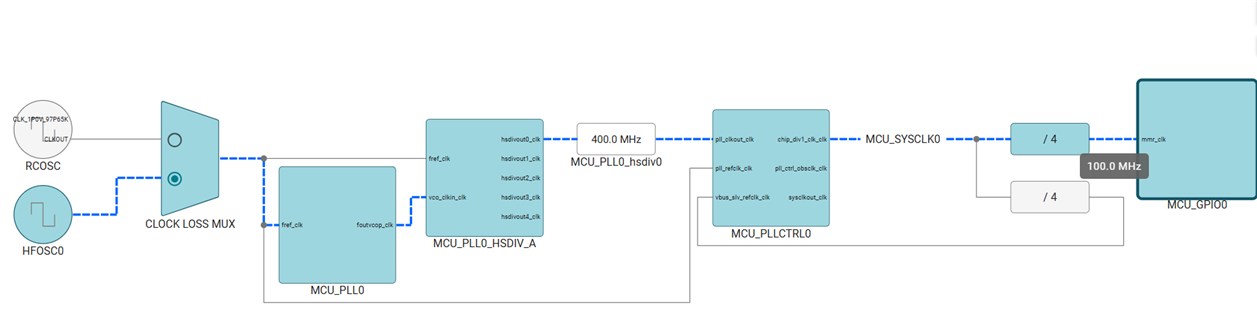
From section "GPIO Integration" / subsection "GPIO Integration in MCU Domain" / Table "MCU_GPIO0 Clocks" of the AM6442 TRM, the input clock feeding the MCU_GPIO0 has frequency of MCU_SYSCLK0 / 4. According to the SYSCONFIG / AM6x Clock Tree (1.1.4) tool , AM6x Clock Tree tool , section Peripherals/General Connectivity/MCU_GPIO0 -> the default MCU_SYSCLK0 frequency is 400 MHz which means that the default MCU_GPIO0 module functional/interface clock frequency is MCU_SYSCLK0 freq / 4 = 400 MHz / 4 = 100 MHz.
This frequency corresponds to a GPIO func. / interface clock period P = 10 ns:
GPIO inputs:
With 1.8 V GPIO power supply:the minimum pulse width allowed on a MCU GPIO input is 2P + 2.6 = 22.6 ns and therefore maximum supported GPIO input frequency is:
With 3.3V GPIO power supply:the minimum pulse width allowed on a MCU GPIO input is 2P + 3.5 = 23.5 ns and therefore maximum supported GPIO input frequency is:
Note that the MAIN_SYSCLK0 freq and MCU_SYSCLK0 can be set with higher frequencies which will increase the max frequencies supported by the GPIO, but because other interface clocks also depend on these clocks, you should be very careful about any decisions to change these clock frequencies.
I hope this answers your questions regarding supported maximum frequencies for the 4 interfaces.