AM3352:During SPI communication with TMS320F28335, AM3352 experiences occasional SPI communication interruptions, data misalignment, or data anomalies

Part Number: AM3352
Other Parts Discussed in Thread: TMS320F28335,

Tool/software:

Dear Sir,

I am an engineer from Kangni Electronics Company in Nanjing, China.We found the following issues when using AM3352 and TMS320F28335 for SPI communication.

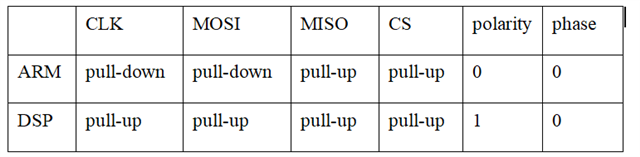
The control board DSP TMS320F28335 and communication board AM3352 are connected through SPI cable plug connection,  ARM as the master device and DSP as the slave device.
During the use of the project, there may be occasional power on situations where SPI cannot communicate, SPI Flashing communication failure, or persistent communication issues.

The Linux u-boot for AM3352 is u-boot-2013.01.01-psp06.00.00.00.

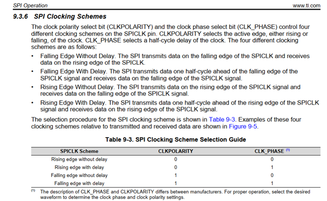
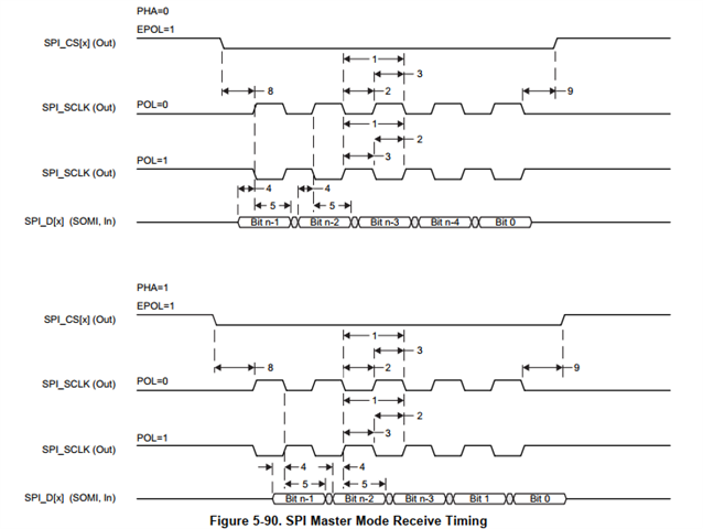
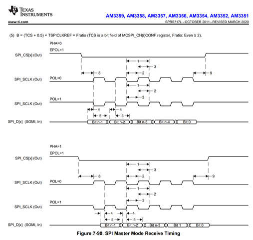
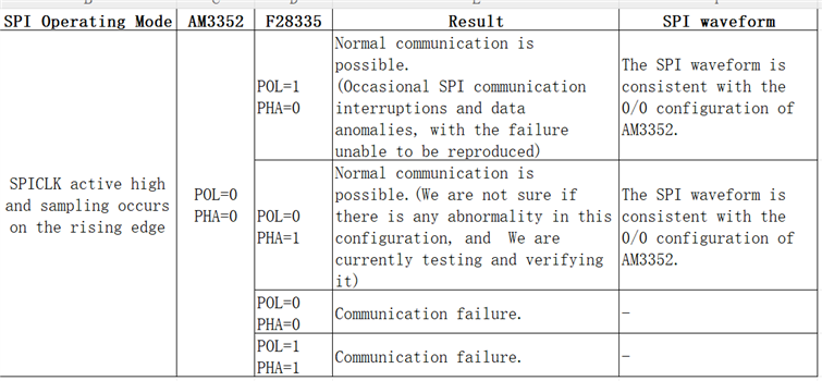
1. Why are the clock timings for data transmission and reception different in the manuals of ARM and DSP chips with the same SPI polarity/phase configuration?
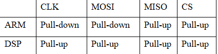
2. The current configuration is as follows, please check if it is correct? What is the standard configuration?

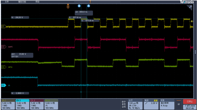
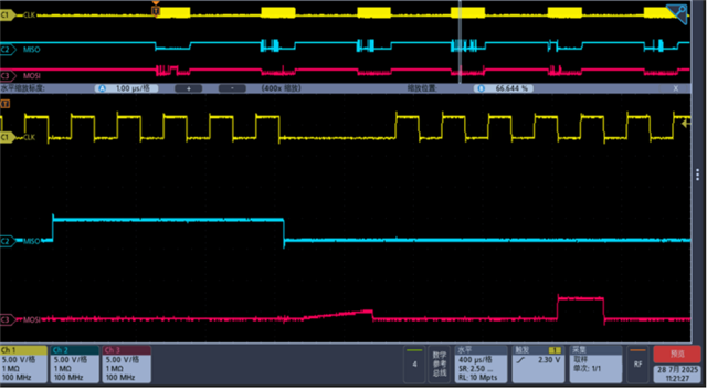
3.The SPI waveform of the current configuration is as follows. Please check if there are any abnormalities? What is the standard waveform?

Thank you!

zhou zhou 

  • Hi Zhou Zhou, 

    Could you point me to the manual of ARM where you see SPI polarity/phase as 0/0?

    I did a quick check in one of our AM335x boards DTS and it seems to me they are configured as you pointed out for DSP

    From pinmux I see:

    https://git.ti.com/cgit/ti-linux-kernel/ti-linux-kernel/tree/arch/arm/boot/dts/am335x-icev2.dts?h=09.03.05#n184

    	spi0_pins_default: spi0_pins_default {
    		pinctrl-single,pins = <
    			AM33XX_PADCONF(AM335X_PIN_SPI0_SCLK, PIN_INPUT_PULLUP, MUX_MODE0)
    			AM33XX_PADCONF(AM335X_PIN_SPI0_D0, PIN_INPUT_PULLUP, MUX_MODE0)
    			AM33XX_PADCONF(AM335X_PIN_SPI0_D1, PIN_INPUT_PULLUP, MUX_MODE0)
    			AM33XX_PADCONF(AM335X_PIN_SPI0_CS0, PIN_INPUT_PULLUP, MUX_MODE0)
    			AM33XX_PADCONF(AM335X_PIN_SPI0_CS1, PIN_INPUT_PULLUP, MUX_MODE0)
    			AM33XX_PADCONF(AM335X_PIN_MCASP0_ACLKR, PIN_INPUT_PULLUP, MUX_MODE7) /* (B12) mcasp0_aclkr.gpio3[18] */
    		>;
    	};

    D0 (MISO - Master In, Slave Out data line) as PIN_INPUT_PULLUP
    D1 (MOSI Master Out, Slave In data line) as PIN_INPUT_PULLUP

    From SPI configuration we have:

    https://git.ti.com/cgit/ti-linux-kernel/ti-linux-kernel/tree/arch/arm/boot/dts/am335x-icev2.dts?h=09.03.05#n305 

    &spi0 {
    	status = "okay";
    	pinctrl-names = "default";
    	pinctrl-0 = <&spi0_pins_default>;
    
    	sn65hvs882@1 {
    		compatible = "pisosr-gpio";
    		gpio-controller;
    		#gpio-cells = <2>;
    
    		load-gpios = <&gpio3 18 GPIO_ACTIVE_LOW>;
    
    		reg = <1>;
    		spi-max-frequency = <1000000>;
    		spi-cpol;
    	};
    
    	spi_nor: flash@0 {
    		#address-cells = <1>;
    		#size-cells = <1>;
    		compatible = "winbond,w25q64", "jedec,spi-nor";
    		spi-max-frequency = <80000000>;
    		m25p,fast-read;
    		reg = <0>;
    
    		partition@0 {
    			label = "u-boot-spl";
    			reg = <0x0 0x80000>;
    			read-only;
    		};
    
    		partition@1 {
    			label = "u-boot";
    			reg = <0x80000 0x100000>;
    			read-only;
    		};
    
    		partition@2 {
    			label = "u-boot-env";
    			reg = <0x180000 0x20000>;
    			read-only;
    		};
    
    		partition@3 {
    			label = "misc";
    			reg = <0x1A0000 0x660000>;
    		};
    	};
    
    };

    Which is SPI Mode 2  (CPOL=1, CPHA=0), same as you DSP polarity/phase configuration

    Questions:

    - Are issues only seen during power up?

    - Which speed are you using?. If possible reduce speed and see if issue persists

    Thank you,

    Paula

  • Hi TI experts,

    We are currently debugging SPI communication issues between an ARM (AM335x) and a DSP (TMS320F28335). We noticed that although both platforms have the same physical SPI mode (for example, both are set to CPOL=1, CPHA=0), the numeric definitions and the resulting timing diagrams appear to be different between the ARM and the DSP documentation.

    1. Reference Material
    • On the ARM side (AM335x), SPI Mode 2 is defined as CPOL=1, CPHA=0.
    • On the DSP side (TMS320F28335), the SPI register bits and timing diagrams seem to interpret CPOL/CPHA slightly differently.

    (See attached screenshots below for documentation examples.)

    2. Our Confusion

    Even when we set both devices to the “same” SPI mode (e.g., CPOL=1, CPHA=0), we sometimes observe data misalignment or timing issues. The timing diagrams in the manuals for ARM and DSP for the same CPOL/CPHA settings also look different in terms of clock/data relationship.

    - Why are the numeric definitions of CPOL/CPHA not fully consistent across different TI chips?
    - How should we reliably match the SPI modes between AM335x and TMS320F28335?
    - Is there an official TI recommendation for cross-platform SPI configuration to avoid such confusion?

    3. Screenshots/Reference


    4. Additional Info
    • Both sides run at 1.5 MHz SPI, master is ARM, slave is DSP.
    • Data format: 8 bits.
    • We observe data misalignment or communication interruption especially after power-on.

    Any advice or clarification would be highly appreciated!

    Thank you!

    zhou zhou 

  • Hi TI Experts,

    We are developing an SPI communication link between an AM3352 (ARM, as SPI master) and a TMS320F28335 (DSP, as SPI slave).
    All SPI signal line pull-up and pull-down settings use the internal configuration of each chip only; there are no external resistors on the board.

    1. Current Configuration

    • SPI master: AM3352, slave: F28335
    • Typical SPI speed: 1.5 MHz
    • All pull-up/down: internal only (no external resistors)

    2. Questions
    • Is this pull-up/pull-down configuration correct and robust for ARM master to DSP slave connection?
    • Is there an official or recommended best practice from TI regarding SPI pull-up/pull-down resistor settings for this scenario?
    • Can improper internal pull-up/down settings cause data misalignment or communication problems, especially at power-up?
    • Should any lines (such as unused pins) be configured differently?

    3. Issue
    • With this setup, we occasionally see data misalignment or lost communication after power-on.
    • We want to make sure the pull-up/down settings are correct on both sides.

    Any official guidance or reference schematic would be greatly appreciated.

    Thank you for your support!

    Best regards,

    zhou zhou

  • Hi Zhou, I am reaching other experts who are more familiar with TMS320F28335. Please allow us a couple of days to come back to you

    thank you,

    Paula

  • Hi Zhou, I got a clarification from a colleague: we cannot assume that mode 2 in AM335x is the same as mode 2 for TMS320F28335.
    The best way is to review the timing graphics. Please take a look at the table below and ensure that both devices are configured to the same SPI operating mode to ensure stable communication.

    SPI Operating Mode

    AM335x

    F2833x

    SPICLK active high and sampling occurs on the rising edge

    POL=0

    PHA=0

    CLKPOLARITY = 0

    CLK_PHASE = 1

    SPICLK active high and sampling occurs on the falling edge

    POL=0

    PHA=1

    CLKPOLARITY = 0

    CLK_PHASE = 0

    SPICLK active low and sampling occurs on the falling edge

    POL=1

    PHA=0

    CLKPOLARITY = 1

    CLK_PHASE = 1

    SPICLK active low and sampling occurs on the rising edge

    POL=1

    PHA=1

    CLKPOLARITY = 1

    CLK_PHASE = 0

    AM335x SitaraTm Processors datasheet (Rev. L)

    thank you,

    Paula

  • hi,Paula,

    Based on your suggestion, we have retested and reorganized as follows:

    The waveforms under F28335 1/0 or 0/1 configurations are shown in the following figure.

    My question are:

    1)According to the SPI clock and phase configuration, why does the waveform of F28335 in the 1/0 configuration match exactly with that in the 0/1 configuration?

    2)Under what circumstances does the F28335 1/0 configuration work abnormally?

    Look forward to your reply.

    Thank you!

    zhou zhou

  • Hello Zhou,

    Paula is out of office for the rest of this week. Please ping the thread if you do not get a response by early next week.

    Regards,

    Nick

  • Hello, Paula,

    Please take some time to look at this issue if you have already returned to work. .

    Thank you very much.

    Zhou zhou

  • Zhou, let me get inputs from our C2000 expert w.r.t your F28335 questions.

    On the other hand, can confirm below combination is working OK?. In your previous message it says it was still being evaluated, so I would like to know the current status

    SPI Operating Mode

    AM335x

    F2833x

    SPICLK active high and sampling occurs on the rising edge

    POL=0

    PHA=0

    CLKPOLARITY = 0

    CLK_PHASE = 1

    thank you,

    Paula

  • HI,Paula,

    When the clock polarity and phase of AM335X are set to 0/0 and the DSP is set to 0/1, there were no issues during laboratory testing. The software will be updated and verified on the train tomorrow.

    Thanks!

    Zhou zhou