This thread has been locked.

If you have a related question, please click the "Ask a related question" button in the top right corner. The newly created question will be automatically linked to this question.

Question of DM814x SD video encoder NTSC format fine tune.

Dear Sir,

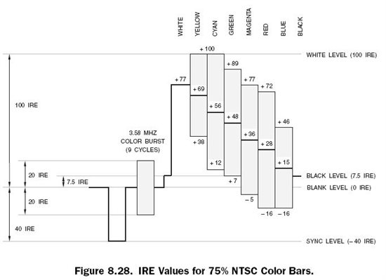
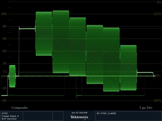
We try to fine tune the SD video encorder NTSC output waveform because it is not good enough.

I can find some register definition, such as, ...

SD_VENC ESTAT,
SD_VENC ECTL,
SD_VENC ETMG0,
SD_VENC ETMG1,
SD_VENC ETMG2,
.....

Unfortunately, I can not find the relation ship between NTSC waveform and these register.

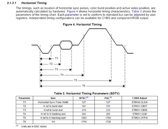
I found an example document from "TMS320DM35x Digital Media System-on-Chip (DMSoC) Video Processing Back End Reference Guide" (SPRUF72C).

This description make us easy to understand the register to NTSC Horizonal Timing relations.

Could you kindly provide the information of where to get the document of DM814x to describe how to fine tune NTSC waveform like this one?

Best regards,

Albert Ke

  • What is wrong with the signal?

    The signal is standards compliant and should not require any changes, hence the VENC documentation is not public.

    BR,

    Steve

  • Hi Steve,

    Thanks for you response.

    I upload 4 pictures to explain our issues. Pic_02, 03 and 04 are measured by equipment "Tektronix 1741C".

    Pic_01: Standard 75%NTSC_Color_Bar

    Pic_02: NTSC Composite Video Signal

    Pic_03: Vectorscope Display

    Pic_04: ColorBar

    Support DM8148 is output 75% color bar.

    Our issues are:

    Issue 1). How can we fine tune to meet 100% color bar?

    Issue 2). The SYNC LEVEL should be -40 IRE, but we only measure about -30 IRE.

    Issue 3). In Pic_03, the vectore display seems become two lines in it. The two lines sould be overlay and become one line.

    Pic_01: 75%NTSC_Color_Bar

    Pic_02: NTSC Composite Video Signal

    Pic_03: Vectorscope Display

    Pic_04: ColorBar


  • OK, first for the vector scope trace... This is currently pretty darned good!!! The 2 lines you see are only telling you that the transition from one color to the next does not occur instantly (which it can't really due to bandwidth limits and filtering of the encoding scheme). You MIGHT be able to improve this slightly by changing the output filter on your PCB to include a little peaking to help the transitions to occur faster, but this then can cause its own issues.

    Regarding the 75%/100% color bar question... I think you are confusing terminology. The term 75% or 100% refers to the source image type you are using in the first place. There are various types of source image used for testing and in reality should be named "75%/75%", 75%/100%", "100%/75%" or "100%/100%" where the first number describes the white level in the image and the second level describes chroma level. To confuse things even further the terms are mixed up when talking about PAL and NTSC testing.

    Bottom line is that for NTSC measurements are usually taken using a 75% reference image in which the white level is at 77 IRE and the chroma excursion is at 100IRE (as you have shown above)

    I think that the Tektronix scope is doing some auto scaling somewhere since the vector scope indicates a slightly low gain but the waveform looks slightly high.

    If you adjust the gain for the vector scope trace you will likely find that the vectors hit the professional grade targets, or get very close to them. Currently you are well within the consumer grade targets.

    Increasing the gain will also increase your sync level closer to 40 IRE, so your 'error' is not actually as high as you might think.

    If you really do want to adjust the sync level then you can adjust register 0x48105e9c. Bits 12:0 set the sync tip level and bits 27:16 set the sync amplitude.

    BR,

    Steve

  • Hi Steve,

    Thanks for your frankly response.

    For your first items:

    We did not add output filter in our PCB. Should we add a filter in it?

    For color bar question:

    This color bar is generated automatically from SD_VENC by set register  0x48105E04 Bit:4.

    Is it means this color bar is 75%/100% color bar?

    For sync level adjust:

    I will test it later.


    Best regards,

    Albert Ke

  • Hi Steve,

    Update one symptom of vector scope trace.

    I found that the vector scope wave form is jitter.

    It means that the wave form is not stable and are rotating a bit all the time.

  • You can add a filter if you want to add peaking. There are many, many ways of doing this with many different implementations. Personally I would not bother since this line seperation on the vector scope is really an artifact of the testing and does not have a huge impact on image quality. A much better measure of image quality is luma and chroma bandwidth measurements. These measurements also tend to be very much subjective too though since there are always tradeoffs with composite video. You can usually make one measurement 'perfect' but then others degrade etc...

    The instability on the vectorscope is usually caused by clock source instability. There is a known issue on Centaurus where there is jitter on the video PLLs under some conditions. The jitter is significantly reduced with the latest PSP releases which configure the PLLs in higher operating frequency ranges which reduce this jitter. Disabling unused digital video output pins also helps to reduce this too.


    ====================

    I removed the script since I just remembered it requires a special kernel build. Sorry.

    ====================

    BR,

    Steve

  • Hi Steve,

    Could you share the version number of "the latest PSP release" with us?

    This can help us to find out this release in web or may be get it from our local FAE.


    Thanks!

    Albert Ke