This thread has been locked.

If you have a related question, please click the "Ask a related question" button in the top right corner. The newly created question will be automatically linked to this question.

AM62P-Q1: PIN connectivity

Part Number: AM62P-Q1

Tool/software:

Hello,

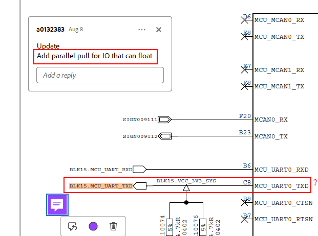
as below show, when our application schematic reviewed by TI, some comments given, but here i'm not understand very clearly about "Add parallel pull for IO that can float"?  does means if this PIN not used in application, we need to add external pull up/down for this PIN? and no external pull needed if this PIN used, right?  thanks!

  • Hello liujian zhang

    Thank you for the schematics review request.

    UART0_TXD0

    For the LVCMOS IO, the buffers are off during reset and after reset.

    The TX will not drive the attached device input until the SOC configures the IO as output and/or enables the pullup.

    In case the attached device input floats until the processor configures the IO, the recommendation is to add external pull.

    This is the case for any SOC IO that has a trace connected but not being driven actively.

    https://www.ti.com/lit/an/spradn4a/spradn4a.pdf

    5.2.1.2 Parallel Pull Resistor
    The recommendation is to provide provision for adding parallel pulls to the processor IO(s) that has a trace
    connected and not being driven actively or for the IOs connected to the attached device inputs that can float
    (to prevent the attached device inputs from floating until driven by the host). Parallel pull polarity and pull value
    depends on the specific peripheral connectivity recommendations, recommendations for improved processor
    performance and reliability, and relevant interface or interface standards requirements.
    Pull values used in processor-specific SK can be used as a starting point and custom board designer can select
    the appropriate pull values based on the recommendations for the processor and attached device, or specific
    board design requirements.
    When a trace is connected to the processor pins (IO pads) and the IOs are not being actively driven (floating),
    a parallel pull is recommended. Processor IO buffers are off during reset and after reset. The IOs are in a high
    impedance state, effectively behaving as an antenna that can pick up noise. Without a parallel pull, the IOs
    are in high impedance state. High impedance makes noise to couple energy easily on the floating signal trace
    and develop a potential that can exceed the IO recommended operating conditions. The potential creates an
    electrical over-stress (EOS) on the IOs. Electrostatic discharge (ESD) protection circuits internal to the processor
    were designed to only protect the device from ESD during handling before being installed on a PCB

    Regards,

    Sreenivasa

  • Hello,

    thanks for your reply! additional questions,

    1. What's the affect of " Processor IO buffers are off during reset and after reset"? if the IO buffer can set to "ON" by SW?

    2. For drive strength, SDIO and LVCMOS can be configured, right? 

  • Hello liujian zhang

    Thank you.

    I am not sure i understand the first question. I will try to answer. Please elaborate the query in case my understanding is not correct.

    What's the affect of " Processor IO buffers are off during reset and after reset"? if the IO buffer can set to "ON" by SW?

    When the TX and RX buffers are off, the IO is in a High-Z state.

    The software can enable the internal pulls and IO buffers after the software boots.

    For drive strength, SDIO and LVCMOS can be configured, right? 

    We currently do not support configuring the drive strength.

    We are evaluating internally on supporting drive strength configuration.

    is thee a use case to configure the drive strength.

    Regards,

    Sreenivasa