AM2732: ISSI IS25LP064D and Macronix MX25L6445EZNI-10Gd cannot perform Flash Boot.

Expert 2440 points
Part Number: AM2732
Other Parts Discussed in Thread: TMDS273EVM, UNIFLASH, SYSCONFIG

Tool/software:

Hi All,

Unable to boot with Flash Boot.

The current situation is as follows.

① Board verification
・Wrote the LED flashing program in No Boot Mode and confirmed that the LED flashes normally.
・Since we were able to read the Flash SFDP Table using QSPI Flash Diag,
we believe that there are no hardware (circuit diagram) issues.

② Functionality verification using the TMDS273EVM
• Conducted functionality verification of the Custom Flash Device using an EVM that is confirmed to function properly.
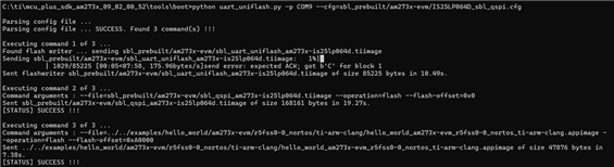
• First, verified functionality using the SBL and Flash writer provided by TI's SDK → Confirmed that Flash Boot is possible.
• Next, following the procedure in "AM273x MCU+ SDK 09.02.00” Adding Support For a Custom Flash Device”
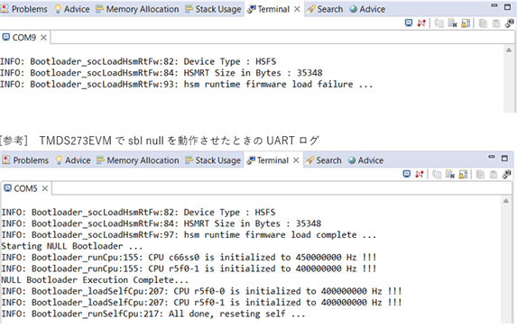
→ Flash boot failed.

https://dev.ti.com/tirex/explore/content/mcu_plus_sdk_am273x_09_02_00_52/docs/api_guide_am273x/CUSTOM_FLASH_SUPPORT_GUIDE.html 

③  Flash
Tested ISSI IS25LP064D and Macronix MX25L6445EZNI-10G,
but neither could perform Flash Boot.
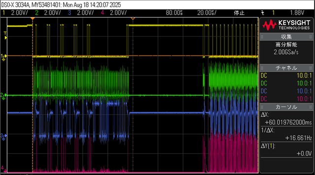
However, when observing the QSPI (CS, CLK, SO, SI) with an oscilloscope,
it appears that some communication is taking place, and it seems to be reading the image from the Flash.
When comparing the QSPI waveforms from a successful Flash Boot using the TMDS273EVM
and the waveforms from a failed Flash Boot on our own board, they appear to be the same.

First, regarding the inability to perform Flash Boot using the Custom Flash Device with the TI EVM mentioned in ②, it seems there may be detailed settings not explained in the SDK user manual.
Could you provide support for this?
(I previously posted the above question but did not receive the expected response.)

Next, if the image is read from Flash but does not boot, what possible causes could there be?

Best Regards,

Ito

  • Hi Ito-san,

    To make the boot from QSPI flash work, you will need to flash both SBL_QSPI and the application image into the QSPI flash. Please refer to the following URL for details:

    AM273x MCU+ SDK: Flash a Hello World example

    Of course, you will need to set the boot mode to Boot from QSPI flash.

    Best regards,

    Ming 

  • Hi All,

    I attempted QSPI boot based on the documentation, but it did not work.
    Furthermore, no UART log was output.

    This is the log when writing to Flash using uart_uniflash.py.
    Flash Writer and SBL QSPI are configured in sysconfig based on the parameters of the flash device being used.
    I believe the write was successful.

    As an additional verification, I performed SOC initialisation using the sbl_null sample.
    When I ran QSPI boot, I obtained the following UART log.
    It seems that the Hsm runtime firmware failed to load.
    Is it necessary to write the Hsm runtime firmware using uniflash or similar to perform QSPI boot?

    Best Regards,

    Ito

  • Hi Ito-san,

    There are two things you may want look into:

    1. Did you power cycle your customer board before you run your uart_uniflash.py?

    2. How did you build your SBL_QSPI (for your customer flash:  ISSI IS25LP064D). The HSM FW should be in the SBL_QSPI image.

    Best regards,

    Ming

  • Hi Ming,

    Thank you for your help,

    1. Did you power cycle your customer board before you run your uart_uniflash.py?

    Yes, I turned off the power, switched to UART Boot mode with the SOP pin, and then ran it.

    2. How did you build your SBL_QSPI (for your customer flash:  ISSI IS25LP064D). The HSM FW should be in the SBL_QSPI image.

    I generated it using the sbl_uart_uniflash project included in MCU+ SDK for AM273x (09.02.00.52).

    Based on the SFDP information obtained from qspi_flash_diag and the information in the data sheet for the Flash (ISSI IS25LP064D),

    we are modifying the Flash parameters in the sysconfig of sbl_uart_uniflash, executing the build, and generating the tiimage.

    I transplanted the EVM standard Flash (GD25B64) onto the board and turned on the power in QSPI Boot mode, but it did not boot.
    Is there any difference between the MPU installed on the evaluation board (TDMS273EVM) and the MPU available on the market?
    The MPU installed on the evaluation board is marked XAM2732C, and the MPU available on the market is marked AM2732C.

    Best Regards,

    Ito

  • 2. How did you build your SBL_QSPI (for your customer flash:  ISSI IS25LP064D). The HSM FW should be in the SBL_QSPI image.

    I generated it using the sbl_uart_uniflash project included in MCU+ SDK for AM273x (09.02.00.52).

    Hi Ito-san,

    You should build your SLB_QSPI (for your customer flash:  ISSI IS25LP064D) based on the C:\ti\mcu_plus_sdk_am273x_09_02_00_52\examples\drivers\boot\sbl_qspi example.

    Best regards,

    Ming

  • Hi Ming,

    Thank you for your reply.

    When building SBL_QSPI, I generated it using C:\ti\mcu_plus_sdk_am273x_09_02_00_52\examples\drivers\boot\sbl_qspi.
    sbl_uart_uniflash was incorrect; sbl_qspi is correct. My apologies.

    Best Regards,

    Ito

  • Hi Ito-san,

    The HSM RT image in the mcu_plus_sdk_am273x_09_02_00_52\source\drivers\hsmclient\soc\am273x\hsmRtImg.h needs to be updated. Here is the new HSM RT image:

    tifs_am273x_hs_fs.release.hsmimage_pg1.2_signed.bin

    You will need to convert it into the array HSMRT_IMG and replace the one in the hsmRtImg.h.

    You will also need to re-build the libraries by calling the following:

    gamke -f makefile.am273x libs

    AND 

    re-build your SBL_QSPI too.

    Best regards,

    Ming

  • Hi All,

    QSPI boot was successful.
    I searched for these procedures and binary data within the SDK but couldn't find them.
    Where are these procedures documented?

    Best Regards,

    Ito

  • Hi Ito-san,

    Glad to hear that the issue has been fixed. This is a bug found after the 09.02.00 release, therefore it is not documented.

    Best regards,

    Ming