DRA829V: How to perform a cold reset?

Part Number: DRA829V
Other Parts Discussed in Thread: TPS6594-Q1, DRA829, TDA4VM

Tool/software:

Hello experts!

SDK 10

In this thread:

DRA829J: Occasional USB drops. MCU_PORz doesn't help.

i shared our problem with USB drop outs and that triggering MCU_PORz doesn't solve the problem. In the thread we concluded that we needed to implement a PMIC reset to get the device out of the faulty state.

We have later seen issues with doing that PMIC toggling. It affects the network interfaces if done too fast, and is being dependent on leakage currents in our circuit solution.

So, my question is: How do I perform a cold reset on the DRA829V, that completely resets everything, without toggling power to the SoC?

Regards,

/Bo

  • Hi Bo,

    What PMIC are you using?  Are you following the EVM PDN-0C topology?  

    Regards,

    Kyle

  • Hi Kyle,

    What PMIC are you using?  Are you following the EVM PDN-0C topology?

    We are using the same PMIC topology as the EVM. PMIC A is a TPS659413 and PMIC B is a TPS659411

    Reading through this thread:

    TPS65219: Cold reset not able to work properly

    even though it's another PMIC, it seems to have a way to choose if a reset should be a warm or a cold one. I can't find that information in the tps6594-q1.pdf datasheet.

    Regards,

    /Bo

  • The TPS65941213-Q1 & TPS659411B4-Q1 PMICs are used to support the J721E (TDA4VM, DRA829) PDN-1A scheme. The complete details of these PMICs are captured in the "TPS65941213-Q1 & TPS659411B4-Q1 PMIC User Guide for J721E, PDN-1A" document available on TI website TPS65941213-Q1 and LP876411B4-Q1 PMIC User Guide for J721E, PDN-1A (ti.com)

    Please be aware there are 2 other PDN schemes that are supported by slightly different PMIC-A TPS659412 & PMIC-B TPS659411 PNs as shown below.

    Optimized TPS65941213-Q1 and TPS65941111-Q1 PMIC User Guide for J721E, PDN-0C (Rev. A)

    TPS65941212-Q1 and TPS65941111-Q1 PMIC User Guide for J721E, PDN-0B (Rev. B) (ti.com)

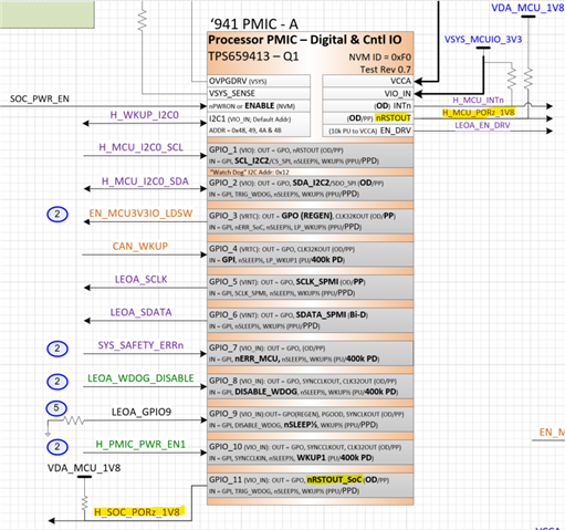
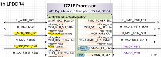
    Typically, an SoC Cold Reset can be accomplished by asserting both MCU_PORz and PORz inputs low which occurs during a normal power-up sequence.  These SoC inputs are connected to the PMIC's nRSTOUT and GPIO_10 outputs with NRSTOUT_SOC function assigned to GPIO10 by the PMIC's NVM settings, as shown in PDN block diagram below.


    Section 8.3.8 in the PMIC's datasheet clarifies nRSTOUT & nRSTOUT_SOC function assigned to a GPIO are associated with the NRSTOUT and NRSTOUT_SOC bits within the PMIC control registers.  SW running on the MCU can assert the NRSTOUT_SOC bit to execute a cold reset of the SoC's main processing domain only.

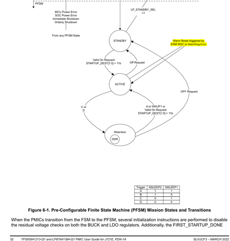
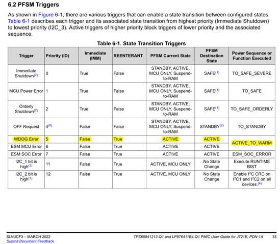
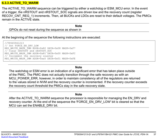
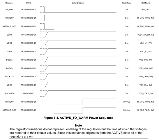
    If you desire to reset both MCU & Main processing domains, then the PMIC's Pre-configurable Finite State Machine (PFSM) must execute a Warm Reset as shown in Fig 6-1 of the J721E PDN-1A PMIC User's Guide (snap-shot below). The system SW can overwrite the WDOG Timer value to force a PMIC Watchdog error resulting in the PMIC executing the desired Warm Reset state transitions.


  • Hello Bill,

    Thank you for that deep detailed explanation.

    These SoC inputs are connected to the PMIC's nRSTOUT and GPIO_10 outputs with NRSTOUT_SOC function assigned to GPIO10 by the PMIC's NVM settings, as shown in PDN block diagram below.

    I guess you mean GPIO11 here, at least that is what all diagrams are depicting.

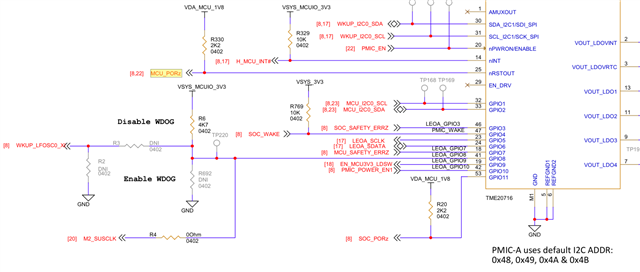
    This is our schematic of relevant parts of PMIC-A:

    Please note that we have an additional MCU in our setup. There is an STM32 acting as power supervisor and main controller of power up/down. In essence, the MCU_PORz signal is directly connected to said STM32, which deassert and assert it as the user presses the reset button.

    Is this a faulty setup? In your description above it seems that a correct reset of the whole SoC should be initiated by the watchdog and not by directly acting upon the MCU_PORz signal. The watchdog would then result in BOTH MCU_PORz and SOC_PORz, which would in turn lead to a full reset.

    Can you comment or advise on this?

    Regards,

    /Bo

  • Using an independent MCU is a valid approach. In fact, asserting MCU_PORz will reset both the MCU & Main processing domains as described in the DM.

    I had suggested the Wdog timer approach in case you did not have an independent MCU and wanted to assert both PORz signals concurrently.

  • Hi Bill,

    That's reassuring to read but we are facing a problem with intermittent drops from our USB-C connection. They seldom occur but when they do, a reset (asserting MCU_PORz) does not take us out of this problem. The unit reboots but the USB-C connection, configured via SERDES, is still not working.

    This is the reason for my original question, how can I perform a reset that -totally- resets the SoC, including ALL peripheral devices?

    Regards,

    /Bo